Table of Contents
Advertisement
Quick Links
Installation and Startup Manual
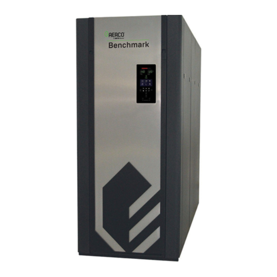
Benchmark
With Edge
Natural Gas, Propane Gas and Dual Fuel
Modulating & Condensing Boilers
Models 750 through 6000
Other documents for this product include:
OMM-0137, GF-211 Operation-Service Manual
OMM-0138, GF-212 Reference Manual
OMM-0139, GF-213 Edge Controller Manual
TAG-0019, GF-2070 Boiler Application Guide
TAG-0022, GF-2050 Vent-Combustion Air Guide
TAG-0047, GF-2030 Benchmark Gas Guide
TAG-0048, GF-2060 Benchmark Power Guide
Applies to serial numbers:
G-20-2773 and above – BMK750 – 5000N
N-20-0282 and above – BMK5000 & 6000
Disclaimer
The information contained in this manual is subject to change without notice
from AERCO International, Inc. AERCO makes no warranty of any kind with
respect to this material, including, but not limited to, implied warranties of
merchantability and fitness for a particular application. AERCO International is
not liable for errors appearing in this manual, not for incidental or
consequential damages occurring in connection with the furnishing,
performance, or use of these materials.
•
GF-210
• 1/6/2021
OMM-136_H
®
Platinum Boilers
®
[ii] Controller
Heating and Hot Water Solutions
AERCO International, Inc. • 100 Oritani Drive • Blauvelt, NY 10913
USA: T: (845) 580-8000 • Toll Free: (800) 526-0288 • AERCO.com
Technical Support • (800) 526-0288 • Mon-Fri, 8 am - 5 pm EST
© 2021 AERCO
Advertisement
Table of Contents

Subscribe to Our Youtube Channel
Related Manuals for Watts AERCO Benchmark OMM-0137


Summary of Contents for Watts AERCO Benchmark OMM-0137
- Page 1 Installation and Startup Manual ® Benchmark Platinum Boilers ® With Edge [ii] Controller Natural Gas, Propane Gas and Dual Fuel Modulating & Condensing Boilers Models 750 through 6000 Other documents for this product include: OMM-0137, GF-211 Operation-Service Manual OMM-0138, GF-212 Reference Manual OMM-0139, GF-213 Edge Controller Manual TAG-0019, GF-2070 Boiler Application Guide TAG-0022, GF-2050 Vent-Combustion Air Guide...
-
Page 2: Table Of Contents
Benchmark Platinum-Edge [ii]: Installation Manual CONTENTS Table of Contents TABLE OF CONTENTS ................... 2 FOREWORD ...................... 5 SECTION 1: SAFETY PRECAUTIONS ..............9 1.1 WARNINGS & CAUTIONS ..................... 9 1.2 EMERGENCY SHUTDOWN ....................10 1.3 PROLONGED SHUTDOWN ....................10 1.4 IMPORTANT – FOR MASSACHUSETTS INSTALLATIONS ..........11 SECTION 2: INSTALLATION ................ - Page 3 Benchmark Platinum-Edge [ii]: Installation Manual CONTENTS SECTION 3: ONAER SETUP ................47 3.1 INTRODUCTION ........................47 3.1.1 Connecting the Ethernet Cable ...................... 48 3.1.2 Confirming the Ethernet Connection ..................... 49 3.1.3 Confirm Ethernet DHCP Configuration ................... 49 APPENDIX A: DIMENSIONAL AND CLEARANCE DRAWINGS ....... 51 •...
- Page 4 Benchmark Platinum-Edge [ii]: Installation Manual CONTENTS (This page intentionally blank) • GF-210 • Technical Support • (800) 526-0288 • Mon-Fri, 8 am - 5 pm EST OMM-136_H 1/6/2021 Page 4 of 62...
-
Page 5: Foreword
Benchmark Platinum-Edge [ii]: Installation Manual FORWARD FOREWORD The AERCO Benchmark (BMK) 750 through 6000 natural gas and propane fueled boilers are modulating and condensing units. They represent a true industry advance that meets the needs of today's energy and environmental concerns. Designed for application in any closed loop hydronic system, the Benchmark's modulating capability relates energy input directly to fluctuating system loads. - Page 6 Benchmark Platinum-Edge [ii]: Installation Manual FORWARD Please consult the Benchmark Venting and Combustion Air Design Guide (TAG-0022, GF- 2050) for a list of allowable and preferred vent materials. The Benchmark's advanced electronics are available in several selectable modes of operation offering the most efficient operating methods and energy management system integration.
- Page 7 Benchmark Platinum-Edge [ii]: Installation Manual FORWARD AERCO Technical Terminology Meanings TERMINOLOGY MEANING Factory Mutual. Used to define boiler gas trains. GF-xxxx Gas Fired (an AERCO document numbering system) Ground Header Hexadecimal Number (0 – 9, A – F) Horse Power Heat Exchanger Hertz (Cycles Per Second) I.D.
- Page 8 Benchmark Platinum-Edge [ii]: Installation Manual FORWARD AERCO Technical Terminology Meanings TERMINOLOGY MEANING Parts per Million Pounds per Square Inch (1 PSI = 6.89 kPa) Point-to-Point (usually over RS232 networks) P&T Pressure and Temperature ProtoNode Hardware interface between BAS and a boiler or water heater Poly Vinyl Chloride, a common synthetic plastic Pulse Width Modulation REF (Ref)
-
Page 9: Section 1: Safety Precautions
Benchmark Platinum-Edge [ii]: Installation Manual SECTION 1 – SAFETY PRECAUTIONS SECTION 1: SAFETY PRECAUTIONS 1.1 WARNINGS & CAUTIONS Installers and operating personnel MUST, at all times, observe all safety regulations. The following warnings and cautions are general and must be given the same attention as specific precautions included in these instructions. -
Page 10: Emergency Shutdown
Benchmark Platinum-Edge [ii]: Installation Manual SECTION 1 – SAFETY PRECAUTIONS 1.2 EMERGENCY SHUTDOWN If overheating occurs or the gas supply fails to shut off, close the manual gas shutoff valve (Figure 1-1) located external to the unit. NOTE: The Installer must identify and indicate the location of the emergency shutdown manual gas valve to operating personnel. -
Page 11: Important - For Massachusetts Installations
Benchmark Platinum-Edge [ii]: Installation Manual SECTION 1 – SAFETY PRECAUTIONS 1.4 IMPORTANT – FOR MASSACHUSETTS INSTALLATIONS Requirements for Massachusetts Installations Boiler Installations within the Commonwealth of Massachusetts must conform to the following requirements: • Boiler must be installed by a plumber or a gas fitter who is licensed within the Commonwealth of Massachusetts. - Page 12 Benchmark Platinum-Edge [ii]: Installation Manual SECTION 1 – SAFETY PRECAUTIONS Requirements for Massachusetts Installations 4. INSPECTION: The state or local gas inspector of the side wall horizontally vented gas fueled equipment shall not approve the installation unless, upon inspection, the inspector observes carbon monoxide detectors and signage installed in accordance with the provisions of 248 CMR 5.08(2)(a)1 through 4.
-
Page 13: Section 2: Installation
Benchmark Platinum-Edge [ii]: Installation Manual SECTION 2 – INSTALLATION SECTION 2: INSTALLATION 2.1 INTRODUCTION This section provides the descriptions and procedures necessary to unpack, inspect and install AERCO Benchmark Platinum Boilers. 2.2 RECEIVING THE UNIT Each Benchmark Boiler System is shipped as a single crated unit. The shipping weight for these BMK models is approximately as follows: •... -
Page 14: Site Preparation
Benchmark Platinum-Edge [ii]: Installation Manual SECTION 2 – INSTALLATION • A 1”, 1-1/2” or 2” Natural Gas Supply Shutoff Valve, and a Propane Shutoff Valve on Propane and Dual Fuel units When optional accessories are ordered, they may be packed within the unit’s shipping container, factory installed on the unit, or packed and shipped in a separate container. - Page 15 Benchmark Platinum-Edge [ii]: Installation Manual SECTION 2 – INSTALLATION NOTE: Ensure that condensate assembly is not located over the housekeeping pad. 4” High Pad Figure 2-1a: BMK750/1000 Clearances NOTE: Ensure that condensate assembly is not located over the housekeeping pad. Figure 2-1b: BMK1500/2000 Clearances •...
- Page 16 Benchmark Platinum-Edge [ii]: Installation Manual SECTION 2 – INSTALLATION NOTE: Ensure that condensate assembly is not located over the housekeeping pad. Housekeeping Pad. Figure 2-1c: BMK2500/3000 Clearances NOTE: Ensure that condensate assembly is not located over the housekeeping pad. Housekeeping Pad. Figure 2-1d: BMK4000-5000N Clearances •...
-
Page 17: Setting The Unit
Benchmark Platinum-Edge [ii]: Installation Manual SECTION 2 – INSTALLATION Figure 2-1e: Benchmark Model 5000 & 6000 Clearances WARNING! Keep the unit area clear and free from all combustible materials and flammable vapors or liquids FOR MASSACHUSETTS ONLY: For Massachusetts installations, the unit must be installed by a plumber or gas-fitter licensed within the Commonwealth of Massachusetts. - Page 18 Benchmark Platinum-Edge [ii]: Installation Manual SECTION 2 – INSTALLATION Figure 2-2a: BMK750/1000 Anchor Bolt Locations Figure 2-2b: BMK1500/2000 Anchor Bolt Locations • GF-210 • Technical Support • (800) 526-0288 • Mon-Fri, 8 am - 5 pm EST OMM-136_H 1/6/2021 Page 18 of 62...
- Page 19 Benchmark Platinum-Edge [ii]: Installation Manual SECTION 2 – INSTALLATION REAR FRONT Figure 2-2c: BMK2500/3000 Anchor Bolt Locations Figure 2-2d. BMK4000-5000N Anchor Bolt Locations Figure 2-2e. BMK5000/6000 Anchor Bolt Locations • GF-210 • Technical Support • (800) 526-0288 • Mon-Fri, 8 am - 5 pm EST OMM-136_H 1/6/2021 Page 19 of 62...
-
Page 20: Housekeeping Pad Requirements
Benchmark Platinum-Edge [ii]: Installation Manual SECTION 2 – INSTALLATION 2.4.3 Housekeeping Pad Requirements To ensure proper condensate drainage, the unit must be installed on a level concrete “housekeeping” pad. The unit must be positioned on the pad such that the condensate assembly is not located over the pad, as shown below. -
Page 21: Lifting Provisions
Benchmark Platinum-Edge [ii]: Installation Manual SECTION 2 – INSTALLATION 2.5 LIFTING PROVISIONS WARNING! When lifting or moving the boiler, DO NOT attempt to manipulate the boiler using the gas train or blower. 2.5.1 BMK750 – 1000 Lifting Provisions Unpack and inspect the unit, then remove the four (4) lag screws securing the boiler to the shipping pallet. -
Page 22: Bmk1500 - 5000N Lifting Provisions
Benchmark Platinum-Edge [ii]: Installation Manual SECTION 2 – INSTALLATION 2.5.2 BMK1500 – 5000N Lifting Provisions Three lifting lugs are provided at the top of the primary heat exchanger as shown in Figure 2-4b. Remove the front top panel from the unit to provide access to the lifting lugs. Remove the four (4) lag screws securing the unit to the shipping skid. -
Page 23: Supply And Return Piping
Benchmark Platinum-Edge [ii]: Installation Manual SECTION 2 – INSTALLATION 2.6 SUPPLY AND RETURN PIPING When connecting the hot water outlet and cold-water inlet to building piping, first make sure the mating surfaces are thoroughly clean. Gaskets of appropriate size for the pipe flange must be provided in the field. - Page 24 Benchmark Platinum-Edge [ii]: Installation Manual SECTION 2 – INSTALLATION o 1.5” (3.81 cm) Propane inlet pipe • 10” (25.4 cm) Air Inlet adapter. NATURAL GAS OR PROPANE INLET HOT WATER OUTLET (SUPPLY) BMK2500 – 5000N BMK1500/2000 AIR INLET SECONDARY WATER INLET (WARMER WATER RETURN) PRIMARY WATER INLET...
-
Page 25: Bmk5000 - 6000 Supply And Return Piping
Benchmark Platinum-Edge [ii]: Installation Manual SECTION 2 – INSTALLATION 2.6.3 BMK5000 – 6000 Supply and Return Piping Benchmark 5000 and 6000 Platinum boilers utilizes 6” (15.24 cm) flanged fittings for the water system supply and return piping connections. The physical location of the supply and return piping connections are shown in Figure 2-5c. -
Page 26: Pressure Relief Valve Installation
Benchmark Platinum-Edge [ii]: Installation Manual SECTION 2 – INSTALLATION 2.7 PRESSURE RELIEF VALVE INSTALLATION An ASME rated Pressure Relief Valve is supplied with each Benchmark Boiler (BMK5000 and 6000 boilers are supplied with one or more valves, depending on the pressure required). The pressure rating for the relief valve must be specified on the sales order. -
Page 27: Condensate Drain And Piping
Benchmark Platinum-Edge [ii]: Installation Manual SECTION 2 – INSTALLATION 2.8 CONDENSATE DRAIN AND PIPING The Benchmark Boiler is designed to condense water vapor from the flue products. Therefore, the installation must have provisions for suitable condensate drainage or collection. See below for information on the condensate drain and piping for the various models. - Page 28 Benchmark Platinum-Edge [ii]: Installation Manual SECTION 2 – INSTALLATION TOP COVER THUMB TRAP INLET SCREWS (4 each) INTEGRAL ADAPTOR AND THUMBSCREW CONDENSATE TRAP COMBUSTION ANALYZER (P/N 24441) PROBE PORT 3/4” NPT NIPPLE UNION EXHAUST MANIFOLD HOSE CLAMP 1” DIAM. HOSE 4”...
-
Page 29: Gas Supply Piping
Benchmark Platinum-Edge [ii]: Installation Manual SECTION 2 – INSTALLATION 2.9 GAS SUPPLY PIPING AERCO’s Benchmark Gas Supply Design Guide, TAG-0047 (GF-2030) must be consulted prior to designing or installing any gas supply piping. WARNING! Never use matches, candles, flames or other sources of ignition to check for gas leaks CAUTION! Many of the soaps used for gas pipe leak testing are corrosive to metals. - Page 30 Benchmark Platinum-Edge [ii]: Installation Manual SECTION 2 – INSTALLATION NOTE: It is the customer’s responsibility to source and purchase the appropriate gas regulator as described above. However, AERCO offers for sale an appropriate regulator, which may be ordered at the time of unit purchase or separately. Contact your AERCO sales representative for more information.
- Page 31 Benchmark Platinum-Edge [ii]: Installation Manual SECTION 2 – INSTALLATION Minimum length NATURAL GAS conforms to INLET Figure 2-8a DRIP LEGS PROPANE INLET MANUAL SHUTOFF VALVES PRESSURE REGULATORS Figure 2-8b: BMK750/1000 Gas Regulator and Manual Shut-Off Valve – Dual Fuel GAS PRESSURE REGULATOR NATURAL GAS INLET GAS INLET...
- Page 32 Benchmark Platinum-Edge [ii]: Installation Manual SECTION 2 – INSTALLATION Minimum length NATURAL GAS MANUAL conforms to Figure 2-8a SHUT-OFF VALVE NATURAL GAS INLET NATURAL GAS PRESSURE REGULATOR PROPANE INLET NATURAL GAS INLET PROPANE MANUAL SHUT- PROPANE INLET OFF VALVE PROPANE PRESSURE REGULATOR Minimum length conforms to Figure 2-8a...
-
Page 33: Manual Gas Shutoff Valve
Benchmark Platinum-Edge [ii]: Installation Manual SECTION 2 – INSTALLATION 2.9.2.1 Massachusetts Installations Only For Massachusetts installations, a mandatory external gas supply regulator must be positioned as shown in Figure 2-8a – 2-8e, above. The gas supply regulator must be properly vented to outdoors. -
Page 34: Power Panel Locations
Benchmark Platinum-Edge [ii]: Installation Manual SECTION 2 – INSTALLATION 2.10.2 Power Panel Locations External AC power connection is made inside the Power Panel, located on the front of the unit, behind the unit’s removable front panel. SECONDARY MAIN POWER POWER PANEL PANEL (with cover) (with cover) -
Page 35: Electrical Power Panel Internal Components
Benchmark Platinum-Edge [ii]: Installation Manual SECTION 2 – INSTALLATION 2.10.3 Electrical Power Panel Internal Components Remove the front panel to access the Power Panel. Run the electrical service through the opening above the Power Panel and make the connections to the Power Breaker in accordance to the Power Panel cover label (see Figure 2-9, above). -
Page 36: Field Control Wiring - I/O Board
Benchmark Platinum-Edge [ii]: Installation Manual SECTION 2 – INSTALLATION WIRE CONDUITS FUSE BLOCK FUSE BLOCK POWER BREAKER 12V POWER SUPPLY TERMINAL BLOCKS Figure 2-10b: BMK2500 – 6000 Power Panel Internal Components NOTES: • The 115V to 24V transformer provides power for the Edge Controller and the Sequencing Isolation Valve. -
Page 37: I/O Board Connections
Benchmark Platinum-Edge [ii]: Installation Manual SECTION 2 – INSTALLATION OXYGEN SENSOR FLOW SENSOR AIR PUMP 4-20mA OUT (AIR EDUCTOR ON BMK5000 & 6000 ONLY) PUMP RELAY BLOWER RELAY BLOCKED FLUE SWITCH Figure 2-12: Secondary Power Panel Terminals I/O BOARD POWER SPARK MONITOR HARNESS 63232 FROM SHELL... - Page 38 Benchmark Platinum-Edge [ii]: Installation Manual SECTION 2 – INSTALLATION NOTE: To facilitate making the connections, these strip can be lifted off the I/O board. The entire strip is then remounted on the I/O board after all connections have been made. If a connector strip is removed, it must be re-mounted in its original orientation (connecting wires arranged around the outside perimeter of the I/O board).
- Page 39 Benchmark Platinum-Edge [ii]: Installation Manual SECTION 2 – INSTALLATION Connector Strip J4 Terminals Pin # Name Description Connection to the Supply Header temperature sensor (2 wire sensor P/N 24410, or 4 wire sensor P/N 61058) for: • Main Loop (in a Variable-Primary application) •...
- Page 40 Benchmark Platinum-Edge [ii]: Installation Manual SECTION 2 – INSTALLATION Connector Strip J6 Terminals Name Pin # Description Remote Interlock Out Connection to an auxiliary device interlock, such as louver open feedback or flow sensor. Remote Interlock Return Delayed Interlock 1 Out Connection to an auxiliary device interlock that requires a delay before the plant starts firing.
-
Page 41: Flue Gas Vent Installation
Benchmark Platinum-Edge [ii]: Installation Manual SECTION 2 – INSTALLATION Connector Strip J14 Terminals Pin # Name Description BAS RS485 + Connection to the building automation system (BAS) network (Modbus RTU, BACnet MSTP). For IP network, use the Ethernet port. BAS RS485 - RS485 Local + RS4585 Ground Reserved for internal use only... -
Page 42: Combustion Air
Benchmark Platinum-Edge [ii]: Installation Manual SECTION 2 – INSTALLATION 2.13 COMBUSTION AIR The Benchmark Venting and Combustion Air Design Guide, TAG-0022 (GF-2050) MUST be consulted before any inlet air venting is designed or installed. Air supply is a direct requirement of ANSI 223.1, NFPA-54, CSA B149.1 and local codes. - Page 43 Benchmark Platinum-Edge [ii]: Installation Manual SECTION 2 – INSTALLATION When operated with the BST system, the BST Manager controls its own isolation valve and sends signals to BST Clients to open or close their isolation valves. After boiler load is satisfied, its isolation valve remains opens for a time interval defined in the SH Valve Close Delay Main Menu →...
- Page 44 Benchmark Platinum-Edge [ii]: Installation Manual SECTION 2 – INSTALLATION Sequencing Isolation Valve Installation Instructions Isolation Valve Harness Wire # Color Signal 1236 Black 24V Common 1237 24V Hot 1238 White Valve analog input 1239 Green Valve analog feedback 1240 Black Delayed interlock 1241 Black...
-
Page 45: Boiler Pump Relay
Benchmark Platinum-Edge [ii]: Installation Manual SECTION 2 – INSTALLATION 2.15 BOILER PUMP RELAY The Benchmark Platinum’s power panel includes a secondary output board with a pump relay that is designed to operate a boiler pump. This relay provides 120VAC with a maximum pilot duty of 3 amps. -
Page 46: Next Steps
Benchmark Platinum-Edge [ii]: Installation Manual SECTION 2 – INSTALLATION 2.16 Next Steps Once the unit is physically installed per the instructions above, the next steps are: • Optionally, implement the onAER option, which allows your unit to be monitored remotely. To implement this option, complete the instructions in the next section, onAER Setup. -
Page 47: Section 3: Onaer Setup
Benchmark Platinum-Edge [ii]: Installation Manual SECTION 3 – ONAER SETUP SECTION 3: onAER SETUP 3.1 INTRODUCTION AERCO has developed new connectivity capabilities to make its IoT offering, onAER, easier for its broad customer base to implement. The onAER feature lets AERCO boilers be monitored remotely. -
Page 48: Connecting The Ethernet Cable
Benchmark Platinum-Edge [ii]: Installation Manual SECTION 3 – ONAER SETUP 2. Once enabled, the following additions parameters appear: Unit Upload Time: Determines how frequently unit data will upload to the server, in • seconds. This will be split between unit data and cascade data (Manager unit only). (Range: 30 to 9999) Cascade Upload Time: Determines how cascade data will upload to the server, in •... -
Page 49: Confirming The Ethernet Connection
Benchmark Platinum-Edge [ii]: Installation Manual SECTION 3 – ONAER SETUP 3.1.2 Confirming the Ethernet Connection Refer to Figure 3-3, below, and complete the following instructions to confirm that the Ethernet cable connection is working. Confirming the Ethernet Connection Instructions 1. Powered the unit on and look for the green LED on the Controllers front face above the onAER soft-key. - Page 50 Benchmark Platinum-Edge [ii]: Installation Manual SECTION 3 – ONAER SETUP (This page intentionally blank) • GF-210 • Technical Support • (800) 526-0288 • Mon-Fri, 8 am - 5 pm EST OMM-136_H 1/6/2021 Page 50 of 62...
-
Page 51: Appendix A: Dimensional And Clearance Drawings
Benchmark Platinum-Edge [ii]: Installation Manual APPENDIX A – DIMENSIONAL AND CLEARANCE DRAWINGS Appendix A: Dimensional and Clearance Drawings Benchmark 750/1000 Dimension Drawing AP-A-891 rev K • GF-210 • Technical Support • (800) 526-0288 • Mon-Fri, 8 am - 5 pm EST OMM-136_H 1/6/2021 Page 51 of 62... - Page 52 Benchmark Platinum-Edge [ii]: Installation Manual APPENDIX A – DIMENSIONAL AND CLEARANCE DRAWINGS Benchmark 750/1000 Single Unit Clearance Drawing SD-A-871 rev C • GF-210 • Technical Support • (800) 526-0288 • Mon-Fri, 8 am - 5 pm EST OMM-136_H 1/6/2021 Page 52 of 62...
- Page 53 Benchmark Platinum-Edge [ii]: Installation Manual APPENDIX A – DIMENSIONAL AND CLEARANCE DRAWINGS Benchmark 750/1000 Zero Side Clearance Drawing SD-A-872 rev C • GF-210 • Technical Support • (800) 526-0288 • Mon-Fri, 8 am - 5 pm EST OMM-136_H 1/6/2021 Page 53 of 62...
- Page 54 Benchmark Platinum-Edge [ii]: Installation Manual APPENDIX A – DIMENSIONAL AND CLEARANCE DRAWINGS Benchmark 1500/2000 Dimension Drawing Number: AP-A-1036 rev B • GF-210 • Technical Support • (800) 526-0288 • Mon-Fri, 8 am - 5 pm EST OMM-136_H 1/6/2021 Page 54 of 62...
- Page 55 Benchmark Platinum-Edge [ii]: Installation Manual APPENDIX A – DIMENSIONAL AND CLEARANCE DRAWINGS Benchmark 1500/2000 Clearance Drawing Number: SD-A-995 rev B • GF-210 • Technical Support • (800) 526-0288 • Mon-Fri, 8 am - 5 pm EST OMM-136_H 1/6/2021 Page 55 of 62...
- Page 56 Benchmark Platinum-Edge [ii]: Installation Manual APPENDIX A – DIMENSIONAL AND CLEARANCE DRAWINGS Benchmark 2500/3000 Dimension Drawing Number: AP-A-915 rev E • GF-210 • Technical Support • (800) 526-0288 • Mon-Fri, 8 am - 5 pm EST OMM-136_H 1/6/2021 Page 56 of 62...
- Page 57 Benchmark Platinum-Edge [ii]: Installation Manual APPENDIX A – DIMENSIONAL AND CLEARANCE DRAWINGS Benchmark 2500/3000 Clearance Drawing Number: SD-A-898 rev E • GF-210 • Technical Support • (800) 526-0288 • Mon-Fri, 8 am - 5 pm EST OMM-136_H 1/6/2021 Page 57 of 62...
- Page 58 Benchmark Platinum-Edge [ii]: Installation Manual APPENDIX A – DIMENSIONAL AND CLEARANCE DRAWINGS Benchmark 4000-5000N Platinum Dimensional Drawing AP-A-1051 rev F • GF-210 • Technical Support • (800) 526-0288 • Mon-Fri, 8 am - 5 pm EST OMM-136_H 1/6/2021 Page 58 of 62...
- Page 59 Benchmark Platinum-Edge [ii]: Installation Manual APPENDIX A – DIMENSIONAL AND CLEARANCE DRAWINGS Benchmark 4000-5000N Clearance & Dimensional Drawing Number: SD-A-1191 rev C • GF-210 • Technical Support • (800) 526-0288 • Mon-Fri, 8 am - 5 pm EST OMM-136_H 1/6/2021 Page 59 of 62...
- Page 60 Benchmark Platinum-Edge [ii]: Installation Manual APPENDIX A – DIMENSIONAL AND CLEARANCE DRAWINGS Benchmark 5000-6000 Dimension Drawing AP-A-1048 rev A • GF-210 • Technical Support • (800) 526-0288 • Mon-Fri, 8 am - 5 pm EST OMM-136_H 1/6/2021 Page 60 of 62...
- Page 61 Benchmark Platinum-Edge [ii]: Installation Manual APPENDIX A – DIMENSIONAL AND CLEARANCE DRAWINGS Benchmark 5000-6000 Zero-Side Clearance Drawing SD-A-919 rev F • GF-210 • Technical Support • (800) 526-0288 • Mon-Fri, 8 am - 5 pm EST OMM-136_H 1/6/2021 Page 61 of 62...
- Page 62 Benchmark Platinum-Edge [ii]: Installation Manual Change Log: Date Description Changed By Rev G: Removed specific site requirements in Section 2.4 in favor of references to Benchmark Electrical Power Design Guide, TAG-0048 (GF-2060), Benchmark Gas Supply Design Guide, TAG-0047 (GF-2030). Added new Section 2.4.3: Housekeeping Pad Requirements.
Need help?
Do you have a question about the AERCO Benchmark OMM-0137 and is the answer not in the manual?
Questions and answers