
Related Manuals for Siemens SITRANS FC720


Summary of Contents for Siemens SITRANS FC720
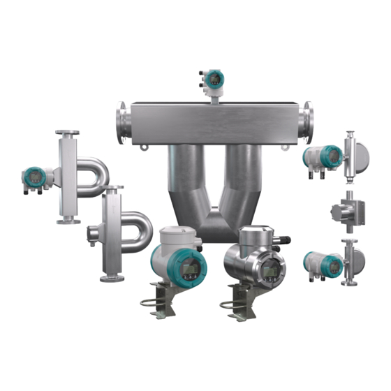
- Page 1 Edition 09/2023 OPERATING INSTRUCTIONS SITRANS F Coriolis flowmeters SITRANS FC720/FC740 www.siemens.com/flow...
-
Page 2: Table Of Contents
Table of contents Table of contents Introduction ............................... Scope of application.......................... Target group............................Document history ..........................Product compatibility ......................... Applicable documents ........................Explanation of safety instructions and symbols ................Safety................................10 Intended use ............................. 10 Technical conditions.......................... 10 General safety instructions........................ 10 Warranty.............................. - Page 3 Table of contents Accuracy of temperature ........................33 Repeatability ............................. 34 Calibration conditions........................34 8.9.1 Mass flow calibration and density adjustment ..............34 8.9.2 Calibration for gases ......................35 8.10 Process conditions ..........................35 8.10.1 Process pressure effect ....................... 35 8.10.2 Process fluid temperature effect ..................
- Page 4 Table of contents 12.2.2 Installation site ........................87 12.2.3 Instructions........................... 88 12.2.4 Sanitary installation......................89 12.3 Unpacking ............................90 12.4 Sensor installation..........................90 12.4.1 General installation rules ..................... 90 12.4.1.1 Avoiding creation of noise....................91 12.4.2 Installation in pipe ........................ 92 12.4.3 Installation recommendation for viscosity function ..............
- Page 5 Table of contents 15.3.5 Performing autozero ......................135 15.4 Advanced settings..........................135 15.4.1 Setting hardware write-protection ..................135 15.4.2 Modbus hardware setting ....................137 15.4.3 PROFIBUS PA hardware setting ..................139 15.4.3.1 Access to Hardware DIP switches ..................139 15.4.3.2 Setting hardware write-protection ..................141 15.4.3.3 Setting the bus address .......................
- Page 6 Table of contents 19.5 Commissioning..........................164 20 Advanced functions ..........................165 20.1 Overview ............................165 20.2 Concentration and petroleum measurement..................166 20.3 Batching function..........................167 20.4 Viscosity function ..........................168 20.5 Tube Health Check ........................... 169 20.6 Measurement of heat quantity......................169 21 Approvals and declarations of conformity .....................
-
Page 7: Introduction
FC7x0 Introduction Scope of application 1 Introduction 1.1 Scope of application These instructions apply to the following Siemens SITRANS FC products: ▪ SITRANS FC1x0 ▪ SITRANS FC6x0 ▪ SITRANS FC7x0 ▪ SITRANS FC5x0 ▪ SITRANS FC Spare transmitter and Spare sensor. -
Page 8: Applicable Documents
– HART A5E52748515 – Profibus PA A5E52748624 – Modbus A5E52748619 All relevant manuals can be downloaded from: http://www.siemens.com/ flowdocumentation. 1.6 Explanation of safety instructions and symbols Warning notices are intended to alert users to potential hazards when working with the Signal words flow meter. - Page 9 FC7x0 Introduction Explanation of safety instructions and symbols Symbols on the Meaning nameplates FM/CSA marking NEPSI marking INMETRO marking DNV GL type approval marking 3-A Sanitary approval marking China RoHS marking Taiwan Safety (TS) marking Russia Pattern approval marking Belarus Pattern approval marking 9 / 180 A5E52748387-AA, 2023/09...
-
Page 10: Safety
Siemens sales organization. Operational safety cannot be ensured in the event of any improper or not intended use. Siemens is not liable for damage arising from such use. The flow meter described in this Operating Instructions is a class A device according to EN 61326-1 and may only be used in an industrial environment. - Page 11 / or environmental harm. ▶ Siemens will not take any liability regarding damage caused by corrosion / erosion. ▶ If corrosion / erosion may happen, the user has to check periodically if the necessary wall thickness is still in place.
- Page 12 Any repair, modification, replacement or installation of replacement parts is permitted ▶ only if it's complying with this Operating Instructions. Other work must be first authorized by Siemens. Siemens does not assume liability for damage caused by unauthorized work on the flow meter or by improper use. 12 / 180...
-
Page 13: Warranty
The warranty terms for this device are described in the quotation. If a defect for which Siemens is responsible occurs in the device during the warranty period, Siemens will repair that defect at its own cost. If you believe that the device is defective, please contact us and provide a detailed description of the problem. -
Page 14: Product Specification
FC7x0 Product specification Scope of delivery 4 Product specification 4.1 Scope of delivery The scope of delivery of the flow meter must be checked for completeness using the following list: Tab. 1: Overview: Scope of delivery of the flow meter Compac Remote Spare Spare... -
Page 15: Identification
SERIAL-No.: MATERIAL: 2023 PT: 60 bar MANUFACTURED: -40...+60 AMB. TEMP.: Made in Germany SIEMENS AG, DE-76181 Karlsruhe Order code Serial number Year of manufacture Ambient temperature range Material wetted parts Flow direction Warning with the request to read the documentation... -
Page 16: Transmitter
FC7x0 Product specification Identification 4.2.1.2 Transmitter Main nameplate SITRANS FCT040 FLOWMETER MODEL: 7ME4474-1B A11-3CB3-Z A10+B01+E06+F11+L51 1234567 SERIAL-No.: 2023 MANUFACTURED: SUPPLY: 24VAC or 100...240VAC, 50/60Hz 24VDC or 100...120VAC; 10W -40...+60 AMB. TEMP.: Made in Germany DE-76181 Karlsruhe Order code Serial number Year of manufacture Power supply range Ambient temperature range... -
Page 17: Order Code Description
FC7x0 Product specification Identification Transmitter label Transmitter Transmitter back cover Label Spare serial number Hardware revision Serial number Date of Ex works/ Update Main software revision Device Revision / Device Revision Compatibility Sensor software revision Type of Communication Indicator software revision Supported "IDENT NUMBERS"... -
Page 18: Flow Meter Components
FC7x0 Product specification Flow meter components Device options (item -Z) can be selected and specified individually. 7 M E 4 4 x 8 9 10 11 13 14 15 16 Product group: MASS Sensor Sensor Transmitter variant Sensor type and size Connector size Process connection / Pressure Process connection / Pressure... - Page 19 FC7x0 Product specification Flow meter components Remote type Process connections Terminal box Cable entry for connecting cable Display cover Sensor connection cover Back cover for inputs and outputs, and power supply Blind plug Inputs/outputs cable entry Power supply cable entry Connecting cable 19 / 180 A5E52748387-AA, 2023/09...
-
Page 20: Transport And Storage
FC7x0 Transport and storage Transport 5 Transport and storage 5.1 Transport The following rules apply when transporting the flow meter: Observe the transport-related instructions on packaging. ▶ In order to avoid damage, do not unpack the flow meter until it is at the installation ▶... -
Page 21: Storage
FC7x0 Transport and storage Storage 5.2 Storage Please note the following rules apply when storing the flow meter: Risk of damage to the flow meter due to storage in a damp environment NOTICE ▶ Protect flow meter from rain and humidity. ▶... -
Page 22: Measuring Principle And Flow Meter Design
FC7x0 Measuring principle and flow meter design Measuring principle 6 Measuring principle and flow meter design 6.1 Measuring principle The measuring principle is based on the generation of Coriolis forces. For this purpose, a driver system (E) excites the two measuring tubes (M1, M2) in their first resonance frequency. - Page 23 FC7x0 Measuring principle and flow meter design Measuring principle The small deformation overlying the fundamental vibration is recorded by means of pick- offs (S1, S2) attached at suitable measuring tube locations. The resulting phase shift Δ φ between the output signals of pick-offs S1 and S2 is proportional to the mass flow. The output signals generated are further processed in a transmitter.
-
Page 24: Flow Meter
FC7x0 Measuring principle and flow meter design Flow meter The measuring tube temperature is measured in order to compensate the effects of Temperature temperature on the flow meter. This temperature approximately equals the fluid measurement temperature and is made available as a measured quantity at the transmitter as well. 6.2 Flow meter The SITRANS FC Coriolis flow meter consists of: ▪... - Page 25 FC7x0 Measuring principle and flow meter design Flow meter Fig. 8: Configuration of the SITRANS FC remote type - long neck Transmitter Sensor terminal box Sensor Connecting cable Process connections All available properties of the SITRANS FC Coriolis flow meter are specified by means of General an order code.
- Page 26 FC7x0 Measuring principle and flow meter design Flow meter Transmitter Properties Order code position 7 ▪ Down to 0.2 % mass flow accuracy for liquids SITRANS FCT020 ▪ Down to 0.75 % mass flow accuracy for gases ▪ Down to 4 g/l (0.25 lb/ft³) accuracy for density ▪...
-
Page 27: Application And Measuring Ranges
▪ Liquids ▪ Gases ▪ Mixtures, such as emulsions, suspensions, slurries Possible limitations applying to measurement of mixtures must be checked with the responsible Siemens sales organization. The following variables can be measured using SITRANS FC: ▪ Mass flow ▪ Density ▪... - Page 28 FC7x0 Application and measuring ranges Measuring range overview FCS700 DN100 FCS700 DN150 FCS700 DN200 Process fluid temperature range -70 – 150 °C -70 – 150 °C Standard (-94 – 302 °F) (-94 – 302 °F) -70 – 230 °C -70 – 230 °C Mid-range [} 37] (-94 – 446 °F) (-94 – 446 °F) 0 – 350 °C 0 – 350 °C High (32 – 662 °F) (32 – 662 °F) - Nominal mass flow - Maximum mass flow - Minimum mass flow The nominal mass flow Q is defined as the mass flow of water (temperature: 20 °C) at...
-
Page 29: Accuracy
FC7x0 Accuracy Overview 8 Accuracy In this chapter, maximum deviations are indicated as absolute values. All accuracy data are given in ± values. 8.1 Overview Achievable accuracies for liquids Maximum deviation D is made up of zero point stability Z and accuracy D , see Mass flow accuracy [} 30]. -
Page 30: Mass Flow Accuracy
36000 49.100 0.064 FCS700 45000 30.000 0.033 DN200 0.75 36000 49.100 0.614 (900000) 39100 39.800 0.398 determined with SITRANS FC HART firmware rev.4. For details, please contact flat your local Siemens sales organization. 30 / 180 A5E52748387-AA, 2023/09... -
Page 31: Accuracy Of Density
FC7x0 Accuracy Accuracy of density Accuracy using water at 20 °C as an example flat Fig. 11: Schematic dependency of the maximum deviation on the mass flow Maximum deviation in % Mass flow in kg/h Mass flow above which D Nominal mass flow in kg/h flat applies, in kg/h flat... -
Page 32: Accuracy Of Mass Flow And Density According To The Order Code
Specified maximum deviation is achieved within the applicable measuring range for density. Notice: In case of a spare sensor combined with a transmitter in use, the original accuracy specification may be affected. For calibration services, please contact Siemens Service department. 8.5.2 For gases... -
Page 33: Volume Flow Accuracy
FC7x0 Accuracy Volume flow accuracy 8.6 Volume flow accuracy 8.6.1 For liquids The following formula can be used to calculate the accuracy of liquid volume flow: ∆ρ × 100% ρ Maximum deviation of volume flow in % Maximum deviation of density in kg/l Δρ... -
Page 34: Repeatability
FC7x0 Accuracy Repeatability (6.5) (6.3) (5.4) (4.5) (3.6) (2.9) (2.7) (2.2) (1.8) (1.6) (0.9) °C -100 (°F) (-148) (32) (212) (392) (572) (68) (-94) (446) (662) Fig. 12: Presentation of temperature accuracy Temperature specification Standard and Medium Temperature specifications High 8.8 Repeatability When using default damping times, the specified repeatability of mass flow, density and For liquids temperature measurements equals half of the respective maximum deviation. -
Page 35: Calibration For Gases
Different gases can be considered by entering characteristic gas sound velocity and related temperature coefficient Only with SITRANS FC HART firmware rev.4 or later. For details please contact your local Siemens sales organization. 8.10 Process conditions 8.10.1 Process pressure effect Process pressure effect is defined as the change in sensor flow and density deviation due to process pressure change away from 1barg reference condition. - Page 36 FC7x0 Accuracy Process conditions Tab. 3: All models Temperature range Uncertainty of flow Standard, ±0.001 % of rate / °C (±0.0005 % of rate / °F) Medium High ±0.0011 % of rate / °C (±0.0006 % of rate / °F) The temperature used for calculation of the uncertainty is the difference between process fluid temperature and the temperature 20°C reference condition.
-
Page 37: Operating Conditions
FC7x0 Operating conditions Process conditions 9 Operating conditions 9.1 Process conditions The pressure and temperature ratings presented in this section represent the design values for the devices. For individual applications (e.g. marine applications with option S2x) further limitations may apply according to the respective applicable regulations. -
Page 38: Pressure
FC7x0 Operating conditions Process conditions Density of gases Rather than being measured directly, density of gas is usually calculated using its reference density, process fluid temperature and process pressure. 9.1.3 Pressure The maximum allowed process pressure depends on the selected process connection and process temperature. - Page 39 FC7x0 Operating conditions Process conditions ASME class 300, EN PN40 p in bar (psi) 50 (725) 40 (580) 30 (435) 26(383) 24(348) 20 (290) 10 (145) T in °C (32) (122) (212) (392) (482) (572) (662) (302) (-58) (°F) (-94) (100) Fig. 14: Allowed process pressure as a function of process connection temperature Process connection compatible to ASME B16.5 class 300 Heat tracing connection for ASME B16.5 class 300 Process and heat tracing connection compatible to EN 1092-1 PN40...
- Page 40 FC7x0 Operating conditions Process conditions ASME class 600, EN PN63 p in bar (psi) 100 (1450) 95(1378) 80 (1160) 63 (914) 60 (870) 55(798) 40 (580) 20 (290) T in °C (-58) (32) (122) (482) (212) (302) (392) (572) (662) (°F) (-94) (100) Fig. 15: Allowed process pressure as a function of process connection temperature Process connection compatible to ASME B16.5 class 600: SITRANS FCS700 with meter size DN100, material wetted parts 1.4404/316L...
-
Page 41: Insulation And Heat Tracing
In such case it is possible to request a customized design from the responsible Siemens sales organization. In the event of a burst pipe, the rupture disc provides an acoustic signal in applications with gases. -
Page 42: Secondary Containment
FC7x0 Operating conditions Ambient conditions In case of subsequent sensor insulation installed by the customer, the following must be noted: ▪ Do not insulate transmitter as well. ▪ In case of remote type, do not insulate the terminal box of the sensor. ▪... - Page 43 FC7x0 Operating conditions Ambient conditions Maximum ambient temperature range remote type Sensor -50 – 80 °C (-58 – 176 °F) with standard cable (option L5x/L6x): Transmitter: -40 – 60 °C (-40 – 140 °F) Sensor -35 – 80 °C (-31 – 176 °F) with fire retardant cable (option L7x/L8x): Transmitter: -35 – 60 °C (-31 – 140 °F) Ambient temperature range for NTEP custody transfer approval Maximum ambient temperature range (C17) -40 – 50 °C (-40 – 122 °F)
-
Page 44: Allowed Ambient Temperature For Sensor
FC7x0 Operating conditions Ambient conditions Ranges and specifications Electromagnetic compatibility (EMC) ▪ IEC/EN 61326-1, Table 2 ▪ IEC/EN 61326-2-3 ▪ IEC/EN 61326-2-5 ▪ NAMUR NE 21 recommendation ▪ DNV-CG-0339 Section 3, Chapter 14 This includes Immunity assessment criterion: The output signal fluctuation is within ±1 % ▪... - Page 45 FC7x0 Operating conditions Ambient conditions Temperature range °C (°F) specification Standard, compact 60 (140) type 40 (104) 20 (68) 0 (32) -20 (-4) -40 (-40) °C -200 -100 (-328) (572) (-148) (32) (212) (392) (°F) Fig. 18: Allowed fluid and ambient temperatures, compact type Tamb Ambient temperature Tpro...
-
Page 46: Temperature Specification In Hazardous Areas
FC7x0 Operating conditions Ambient conditions Temperature range °C (°F) specification Medium, remote type 80 (176) 75 (167) 60 (140) 58 (136) 40 (104) 20 (68) 0 (32) -20 (-4) -35 (-31) -40 (-40) °C -200 -100 (-328) (-148) (32) (392) (212) (°F) (-94) - Page 47 FC7x0 Operating conditions Ambient conditions The following figure shows the relevant positions of the order code: Order code: Pos. 6: 7 Pos. 12: 1, 4 7 M E 4 4 x Pos. 14: A, B 8 9 10 11 13 14 15 16 Pos.
- Page 48 FC7x0 Operating conditions Ambient conditions The following figure shows the relevant positions of the order code: Order code: Pos. 6: 7 Pos. 12: 1, 4 7 M E 4 4 x Pos. 14: C, E, G 8 9 10 11 13 14 15 16 Pos.
- Page 49 FC7x0 Operating conditions Ambient conditions The following figure shows the relevant positions of the order code: Order code: Pos. 6: 7 Pos. 12: 1, 4 7 M E 4 4 x Pos. 14: D, F, H 8 9 10 11 13 14 15 16 Pos.
- Page 50 FC7x0 Operating conditions Ambient conditions The following figure shows the relevant positions of the order code: Order code: Pos. 6: 7 Pos. 12: 2, 5 7 M E 4 4 x Pos. 14: D, F, H 8 9 10 11 13 14 15 16 Pos.
- Page 51 FC7x0 Operating conditions Ambient conditions The following figure shows the relevant positions of the order code: Order code: Pos. 6: 7 Pos. 12: 3, 6 7 M E 4 4 x Pos. 14: D, F, H 8 9 10 11 13 14 15 16 Pos.
-
Page 52: Mechanical Specification
FC7x0 Mechanical specification Design 10 Mechanical specification 10.1 Design The SITRANS FC7x0 flow meter is available with two design types: ▪ Compact type, sensor and transmitter are firmly connected ▪ Remote type – Standard neck – Long neck Fig. 22: Standard and long neck Fig. 23: Standard and long neck FCS700 DN200 7 M E 4 4 x 8 9 10 11... - Page 53 FC7x0 Mechanical specification Design Design type Design version Process fluid Order code position 14 temperature range Compact type Direct connection Standard A, B Standard neck C, E, G Medium Standard Remote type Long neck Medium D, F, H High If insulation (e.g. device option Jxx) is planned, it is mandatory to use the remote type with long neck.
-
Page 54: Material
FC7x0 Mechanical specification Material 10.2 Material 10.2.1 Sensor Material wetted parts Sensor parts which are wetted by process fluid are available with the following materials: Material Order code position 12 Stainless steel 1.4404/316L 1, 2, 3 Nickel alloy C-22/2.4602 4, 5, 6 For FCS700 DN200 S: Flow splitter material is 1.4409/CF3M Not for FCS700 DN200 The customer is responsible to ensure chemical compatibility of the material of the wetted... -
Page 55: Nameplates
FC7x0 Mechanical specification Material Display window This is relevant for all transmitters having a display: 7 M E 4 4 x 8 9 10 11 13 14 15 16 Display material Order code position 16 Glass Bracket material The bracket is available for remote type devices only: Bracket material Design type Order code... -
Page 56: Process Connections, Dimensions And Weights Of Sensor
FC7x0 Mechanical specification Process connections, dimensions and weights of sensor 10.3 Process connections, dimensions and weights of sensor ø 102 L1 ±5 ø 102 Remote type Remote type Compact type (with standard neck) (with long neck) (with transmitter) Fig. 24: Dimensions in mm Compact type Remote type Remote/ Compact type... - Page 57 FC7x0 Mechanical specification Process connections, dimensions and weights of sensor L1 ±5 Ø 102 Process connection Heat tracing connection option J12...J14, L4 ±5 Insulation housing J16...J18 option J10, J12...J14, Purging J16...J18 option J16...J18 Fig. 26: Dimensions in mm: version with insulation housing Tab. 20: Dimensions without length L1 Meter size in mm (inch)
- Page 58 FC7x0 Mechanical specification Process connections, dimensions and weights of sensor Process connections 7 M E 4 4 7 compatible to ASME B16.5 (AISI 8 9 10 11 13 14 15 16 316/ AISI 316L dual certified) Order code: Tab. 22: Overall length L1 and weight of sensor (process connections: ASME, wetted parts: stainless steel) Pos.
- Page 59 FC7x0 Mechanical specification Process connections, dimensions and weights of sensor Process Order code pos. SITRANS FC SITRANS FC SITRANS FC connections DN100 DN150 DN200 Weight Weight Weight 10+11 in mm in kg in mm in kg in mm in kg (inch) (lb) (inch)
- Page 60 FC7x0 Mechanical specification Process connections, dimensions and weights of sensor Tab. 23: Overall length L1 and weight of sensor (process connection: ASME, wetted parts: Ni alloy C-22/2.4602) Process Order code pos. SITRANS FC SITRANS FC SITRANS FC connections DN100 DN150 DN200 Weight Weight Weight...
- Page 61 FC7x0 Mechanical specification Process connections, dimensions and weights of sensor Tab. 24: Overall length L1 and weight of sensor (process connections: EN, wetted parts: stainless steel) 61 / 180 A5E52748387-AA, 2023/09...
- Page 62 FC7x0 Mechanical specification Process connections, dimensions and weights of sensor Process Order code pos. FCS700 DN100 FCS700 DN150 FCS700 DN200 connections Weight Weight Weight 10+11 in mm in kg in mm in kg in mm in kg (inch) (lb) (inch) (lb) (inch) (lb)
- Page 63 FC7x0 Mechanical specification Process connections, dimensions and weights of sensor Process Order code pos. FCS700 DN100 FCS700 DN150 FCS700 DN200 connections Weight Weight Weight 10+11 in mm in kg in mm in kg in mm in kg (inch) (lb) (inch) (lb) (inch) (lb)
- Page 64 FC7x0 Mechanical specification Process connections, dimensions and weights of sensor Process Order code pos. FCS700 DN100 FCS700 DN150 FCS700 DN200 connections Weight Weight Weight 10+11 in mm in kg in mm in kg in mm in kg (inch) (lb) (inch) (lb) (inch) (lb)
- Page 65 FC7x0 Mechanical specification Process connections, dimensions and weights of sensor Process Order code pos. FCS700 DN100 FCS700 DN150 FCS700 DN200 connections Weight Weight Weight 10+11 in mm in kg in mm in kg in mm in kg (inch) (lb) (inch) (lb) (inch) (lb)
- Page 66 FC7x0 Mechanical specification Process connections, dimensions and weights of sensor Process Order code pos. FCS700 DN100 FCS700 DN150 FCS700 DN200 connections Weight Weight Weight 10+11 in mm in kg in mm in kg in mm in kg (inch) (lb) (inch) (lb) (inch) (lb)
- Page 67 FC7x0 Mechanical specification Process connections, dimensions and weights of sensor Process Order code pos. FCS700 DN100 FCS700 DN150 FCS700 DN200 connections Weight Weight Weight 10+11 in mm in kg in mm in kg in mm in kg (inch) (lb) (inch) (lb) (inch) (lb)
- Page 68 FC7x0 Mechanical specification Process connections, dimensions and weights of sensor Process Order code pos. FCS700 DN100 FCS700 DN150 FCS700 DN200 connections Weight Weight Weight 10+11 in mm in kg in mm in kg in mm in kg (inch) (lb) (inch) (lb) (inch) (lb)
- Page 69 FC7x0 Mechanical specification Process connections, dimensions and weights of sensor Process connections 7 M E 4 4 7 compatible to JIS B 2220 (AISI 316/ 8 9 10 11 13 14 15 16 AISI 316 L) Order code: Tab. 26: Overall length L1 and weight of sensor (process connections: JIS, wetted parts: stainless Pos.
- Page 70 FC7x0 Mechanical specification Process connections, dimensions and weights of sensor Order code position FCS700 DN100 Y30 min Y30 max 10+11 in mm (S31) (inch) in mm (inch) 1160 1200 D1, D2, D3, A8, A1, L2, L4, C3, B0, B1, B4, B5, A4, A5 (45.7) (47.2) 1160...
-
Page 71: Transmitter Dimensions And Weights
FC7x0 Mechanical specification Transmitter dimensions and weights 10.4 Transmitter dimensions and weights Transmitter dimensions 87.8 67.8 Fig. 27: Dimensions of transmitter in mm (left: transmitter with display, right: transmitter without display) Tab. 31: Overall length L1 - L4 and height H1 - H4 of transmitter (material: stainless steel, aluminum) Material L1 in mm... - Page 72 FC7x0 Mechanical specification Transmitter dimensions and weights Order code Design type Housing material of Weight pos. 14 transmitter in kg (lb) C, D, E, F Aluminum max. 4.4 (9.7) Remote G, H Stainless steel 12.5 (27.6) 72 / 180 A5E52748387-AA, 2023/09...
-
Page 73: Transmitter
FC7x0 Transmitter 11 Transmitter SITRANS FCT020 Transmitter SITRANS FCT040 Transmitter For general purpose application For demanding and critical application SITRANS SITRANS SIEMENS SIEMENS Transmitter Advanced Total Health Dynamic Wizard for easy Event type functions Check Pressure setup Management Compensation acc. NAMUR... -
Page 74: Electrical Interfaces
FC7x0 Transmitter Electrical interfaces ● Supported / - not supported 11.1 Electrical interfaces Depending on the selected interface protocol up to 4 in and/or outputs (I/O) are available, partially configurable. 7 M E 4 4 x 8 9 10 11 13 14 15 16 (I/O1) (I/O2) (I/O3) (I/O4) Order code... - Page 75 FC7x0 Transmitter Electrical interfaces For HART communication devices, it is supplied on the current output lout1. The current output may be operated in compliance with the NAMUR NE43 standard. Value Nominal output current 4 – 20 mA Maximum output current range 2.4 –...
-
Page 76: Analog Inputs
FC7x0 Transmitter Electrical interfaces 11.1.1.2 Analog inputs An individual analog power input is available for external analog devices. Active current input The active current input lin is provided for connecting a two-wire transmitter with an output signal of 4 – 20 mA. Value Nominal input current range 4 –... -
Page 77: Analog Output Specification
FC7x0 Transmitter Electrical interfaces 11.1.1.3 Analog output specification If mass- or volume flow, density, temperature, pressure or concentration is measured via Analog output current output Iout two additional deviation effects have to be taken into account. specification lout ▪ The Iout –base specification ∆I contains all combined effects of output adjustment, base linearity, power supply variation, load resistance variation, short and long term drift for... - Page 78 FC7x0 Transmitter Electrical interfaces Terms Value Internal power supply 24 V ±20 % Maximum pulse rate 10000 pulses/s Frequency range 0 – 12.5 kHz SITRANS FC 24 V P/Sout+ P/Sout- Fig. 34: Active pulse output connection P/Sout Load resistance ① Electronic counter ②...
- Page 79 FC7x0 Transmitter Electrical interfaces SITRANS FC 24 V P/Sout+ P/Sout- Fig. 36: Active pulse output P/Sout with internal pull-up resistor Electronic counter ① Maximum voltage and correct polarity must be observed for wiring. Passive pulse output P/Sout Value Maximum load current ≤...
- Page 80 FC7x0 Transmitter Electrical interfaces SITRANS FC 24 V P/Sout+ P/Sout- Fig. 39: Active status output connection P/Sout External device with load resistance ① Active status output Value P/Sout with internal Internal pull-up resistor 2.2 kΩ pull-up resistor Internal power supply 24 V ±20 % SITRANS FC 24 V...
-
Page 81: Digital Inputs
FC7x0 Transmitter Electrical interfaces A relay must be connected in series to switch alternating voltage. Output signals according to EN 60947-5-6 (previously NAMUR, worksheet NA001): Passive pulse or status output P/Sout 1kΩ SITRANS FC (NAMUR) P/Sout+ 10kΩ P/Sout- Fig. 43: Passive pulse or status output with switching amplifier connected in series Passive pulse or status output ①... - Page 82 FC7x0 Transmitter Electrical interfaces Order code Connection terminal assignment position -Z I/O1 +/- I/O2 +/- I/O3 +/- I/O4 +/- Iout1 P/Sout1 Sout P/Sout2 E06+F12 Write-protect Active Passive Passive Passive Iout1 P/Sout1 P/Sout2 E06+F13 Write-protect Active Passive Passive P/Sout2 Iout1 P/Sout1 Active E06+F21 Write-protect...
-
Page 83: Modbus
FC7x0 Transmitter Electrical interfaces Iout2 Analog current output P/Sout1 Pulse or status output P/Sout2 Pulse or status output Intrinsically safe outputs are only available in combination with selecting Ex approval of the device, see order code position 15 in the table of chapter Order code description. 11.1.4 Modbus Modbus interface is available with configurable I/O option. - Page 84 FC7x0 Transmitter Electrical interfaces SITRANS FC Fig. 45: PROFIBUS PA connection PROFIBUS PA ① Termination ② DP/PA-Coupler ③ PROFIBUS DP ④ HOST ⑤ Supported Functions Profile PA Rev. 3.02 compliant, supporting: ▪ Condensed Status (NE107) ▪ Device identification number (IDENT_NUMBER) adaption Function Blocks Description Flow...
-
Page 85: Power Supply
For remote type devices, a connecting cable has to be used to connect the sensor to the transmitter. The device specifications, stated in this document, are valid only if one of the original Siemens connecting cables is used. Cable length limitations to be considered:... -
Page 86: Installation
FC7x0 Installation Location and position of installation 12 Installation 12.1 Location and position of installation SITRANS FC Coriolis flow meters can be mounted horizontally, vertically and at an incline. The measuring tubes should be completely filled with the fluid during flow measurement as accumulations of air or formation of gas bubbles in the measuring tube may result in errors in measurement. -
Page 87: Installation Instructions
FC7x0 Installation Installation instructions Installation position Fluid Description Vertical, direction of flow towards the top (recommended) The sensor is installed on a pipe with the direction of flow towards the top. Accumulation of gas bubbles or solids Liquid/gas is avoided. This position allows for complete self-draining of the measuring tubes. -
Page 88: Instructions
▶ If the plan calls for installing two sensors of the same kind back-to-back, use a ▶ customized design. Contact the responsible Siemens sales organization. Operate the flow meter below an elevation of 2000 m above sea level. ▶ If possible, avoid installing the flow meter at the end of a downpipe. -
Page 89: Sanitary Installation
FC7x0 Installation Installation instructions Avoid letting the sensor run idle while taking the measurement, e.g. when installed in ▶ front of an air gap to containers in case of filling applications. Doing so may result in incorrect measurements. To avoid this, install a restriction in the open downpipe or use an orifice gauge with a diameter smaller than the nominal pipe width. -
Page 90: Unpacking
FC7x0 Installation Unpacking For compliance with 3-A sanitary standards, a vertical installation of sensor with fluid Sensor installation ▶ flowing upwards (self-draining) is recommended, as shown in figure below. (remote or compact version) Fig. 50: Vertical (self-draining) installation A horizontal installation of sensor with tubes down, as shown in figure below, shall be ▶... -
Page 91: Avoiding Creation Of Noise
FC7x0 Installation Sensor installation Fig. 52: Avoid: Slope and mismatch Avoid fixing anything directly to the sensor. Doing so may result in increased ▶ deviations. Fig. 53: Installation to be avoided: Fixing the sensor Fig. 54: Recommended installation: use the piping to support the sensor Pipe Sensor Secure pipes before installing the flow meter. -
Page 92: Installation In Pipe
FC7x0 Installation Sensor installation 12.4.2 Installation in pipe Depending on process connections, the sensor is connected to the pipe by means of flanges, terminals or thread. The order code provides information on the process connections selected. Risk of injury due to escaping fluids and damage, if fixing materials are DANGER inappropriate or not professionally installed ▶... - Page 93 FC7x0 Installation Sensor installation Fig. 56: Fixing the flange Pipe flange Gasket Sensor flange Bolt For process connections with an internal thread, the connection must be installed in Internal thread accordance with the following figure. connection Fig. 57: Internal thread connection Sensor Gasket (not use in case of NPT) Pipe Use of seal tape for installation...
-
Page 94: Installation Recommendation For Viscosity Function
FC7x0 Installation Sensor installation 12.4.3 Installation recommendation for viscosity function In order to use this function an external differential pressure transmitter (separate order) measuring the pressure difference at the flow line is necessary. The accuracy of the estimated viscosity is strongly depending on the accuracy of the pressure transmitter and the correct position and implementation of the pressure taps. -
Page 95: Insulation And Heat Tracing
FC7x0 Installation Insulation and heat tracing PROFIBUS PA Fig. 59: Positioning of pressure taps / PROFIBUS PA communication line Mounting flanges PROFIBUS PA Communication ① ⑤ line Pressure taps PROFIBUS PA Junction box ② ⑥ SITRANS FC Other flow elements ③ ⑦... -
Page 96: Customer-Supplied Insulation
FC7x0 Installation Transmitter installation Risk of overheating the transmitter due to increased ambient temperature WARNING Failure of measuring electronics ▶ Observe the maximum allowable ambient temperature for the transmitter. ▶ Install the transmitter at a sufficient distance from heat sources. 12.5.2 Customer-supplied insulation For insulation provided by the customer it is important to select a sensor with the appropriate design type (remote type, sensor with long neck). - Page 97 FC7x0 Installation Transmitter installation 2. Using an Allen wrench (size: 3.0), turn the locking screw on display screw plug clockwise to remove. 3. Unscrew display cover from transmitter housing. 4. Remove the two screws from the display. 97 / 180 A5E52748387-AA, 2023/09...
- Page 98 FC7x0 Installation Transmitter installation 5. Remove the display from housing by pulling forward. 6. Rotate display and push back into housing in the orientation desired. The display can be removed and replaced by loosening the connector. NOTICE 98 / 180 A5E52748387-AA, 2023/09...
-
Page 99: Rotating Transmitter Housing (Compact Type)
FC7x0 Installation Transmitter installation 7. Tighten screws. 8. Screw display cover back onto transmitter housing. 9. Using an Allen wrench (size: 3.0), turn the locking screw on display screw plug counter-clockwise to tighten. 12.6.2 Rotating transmitter housing (compact type) The transmitter housing can be installed in any one of four orientations. Short-circuit hazard caused by penetrating water WARNING Failure of measuring electronics... - Page 100 FC7x0 Installation Transmitter installation Insufficient sensor grounding connection WARNING Electric shock and ignition in hazardous areas ▶ Use a minimum torque of 4.3 Nm when tightening the screws. Damage to flow meter NOTICE Rotating the transmitter housing several times in the same direction may damage the connection between sensor and transmitter.
-
Page 101: Rotating The Terminal Box (Remote Type)
FC7x0 Installation Transmitter installation 4. Place transmitter housing. 5. Tighten the four fixing screws. 12.6.3 Rotating the terminal box (remote type) The terminal box can be installed in any one of four orientations. 1. Loosen the four fixing screws and remove the cover. 2. -
Page 102: Installing Transmitter On Pipe (Remote Type)
FC7x0 Installation Transmitter installation 3. By using an Allen wrench, remove the bottom fixing screws and rotate the terminal box at an angle of 90°, 180° or 270°. 4. Place the terminal box and tighten the bottom fixing screws using a minimum torque of 7.4 Nm. - Page 103 FC7x0 Installation Transmitter installation Installation at high vibration levels NOTICE The mounting bracket for the pipe installation of the transmitter may not be suitable for installation environments with very high levels of vibration. In this case the user is advised to employ more rugged methods of fixation using the threaded bottom holes directly.
-
Page 104: Installation Check List
FC7x0 Installation Installation check list 3. Fasten retaining clip to bracket using the nuts. 12.7 Installation check list The following checks must be performed once the flow meter is installed in the pipe: Check Performed? State and specification of device ▪... -
Page 105: Wiring
Risk of injury due to electrical shock, as well as sparking and damage to WARNING the flow meter, if an inappropriate connecting cable is used ▶ It is imperative that an original connecting cable and original glands from Siemens are used. ▶ Install cables tension-free. -
Page 106: Grounding Connections
FC7x0 Wiring Grounding connections Be aware that improper earthing, false wiring and use of cable out of specification may NOTICE lead to instrument damage and/or disturbance of other sensitive electrical equipment due to increased electromagnetic emissions/immunity. Be aware that wrong input voltage may lead to disturbance of other sensitive electrical NOTICE equipment due to increased electromagnetic emissions. -
Page 107: Connecting Cable Installation
Siemens are used. In order to ensure the IP code, the cable must be professionally installed at the entries. If necessary, the cable may be shortened using the enclosed termination kit. -
Page 108: Connection Terminals
Connecting cable installation If the connecting cable, included in the delivery, is too short, additional lengths can be procured through the Siemens sales organization. 13.3.1 Connection terminals The delivery includes an operating tool for connecting the connecting cable to the connection terminals. - Page 109 FC7x0 Wiring Connecting cable installation green blue white brown yellow drain wire Fig. 65: Terminated standard connecting cable L5x/L6x, transmitter side Connection scheme of standard connecting cable option L5x/L6x Tab. 32: Version coaxial wire Standard connecting cable option L5x/L6x Signal Coaxial wire Coaxial wire pair colour Wire type Wire colour...
- Page 110 FC7x0 Wiring Connecting cable installation Installation of fire retardant connecting cable option L7x/L8x D– D– S1– S1– S2– S2– Fig. 66: Transmitter and sensor interconnection diagram Sensor Transmitter Potential equalization system shield wire Fig. 67: Terminated fire retardant connecting cable L7x/L8x, transmitter side Connection scheme of fire retardant connecting cable option L7x/L8x Tab. 34: Version L7x/L8x L7x/L8x cable...
-
Page 111: Connecting The Connecting Cable To Sensor
FC7x0 Wiring Connecting cable installation 13.3.2 Connecting the connecting cable to sensor Use the cable end without shield wire to connect to the sensor (observe labeling). NOTICE If the cable is not terminated or was shortened, observe the separate instructions in the NOTICE included terminating set. -
Page 112: Connecting The Connecting Cable To Transmitter
FC7x0 Wiring Connecting cable installation 13.3.3 Connecting the connecting cable to transmitter 1. Loosen the four screws from the sensor connection cover and remove cover. 2. Remove connector nut from cable gland and pull out clamped insert. 3. Push cable through connector nut and clamped insert. 4. -
Page 113: Transmitter
FC7x0 Wiring Transmitter 13.4 Transmitter 13.4.1 HART and Modbus communication 13.4.1.1 HART communication For devices with HART communication, the HART interface, along with the analog signal, HART interface is available at the output Iout1. A load resistance of 230 – 600 Ω at Iout1 is recommended. -
Page 114: Output Signals
FC7x0 Wiring Transmitter Master Pull Up Balanced Pair Common Pull Down LT: Line Termination SITRANS FC Slave n Fig. 69: Modbus connection 13.4.1.3 Output signals All circuits for inputs, outputs and power supply are galvanically isolated from each other. Galvanic isolation One or two current outputs are available depending on order code position -Z. - Page 115 FC7x0 Wiring Transmitter U - 10.5 V 0.0236 A 10.5 U in V Fig. 71: Maximum load resistance as a function of an external power supply voltage Load resistance External power supply voltage The diagram shows the maximum load resistance R as a function of voltage U of the connected voltage source.
- Page 116 FC7x0 Wiring Transmitter Connection of an electronic counter Active pulse output P/Sout Maximum voltage and correct polarity must be observed for wiring. Terms Value Load resistance > 1 kΩ Internal power supply 24 V ±20 % Maximum pulse rate 10000 pulses/s Frequency range 0 –...
- Page 117 FC7x0 Wiring Transmitter Active pulse output Value P/Sout with internal Internal power supply 24 V ±20 % pull-up resistor Internal pull-up resistor 2.2 kΩ Maximum pulse rate 10000 pulses/s Frequency range 0 – 12.5 kHz SITRANS FC 24 V P/Sout+ P/Sout- Fig. 75: Active pulse output P/Sout with internal pull-up resistor Electronic counter...
- Page 118 FC7x0 Wiring Transmitter SITRANS FC Pulse+ Pulse- Fig. 77: Passive pulse output connection with electronic counter Passive pulse ① Load resistance ② Electronic counter ③ SITRANS FC Pulse+ Pulse- Fig. 78: Passive pulse output connection with electromechanical counter Passive pulse ① Protective diode ②...
- Page 119 FC7x0 Wiring Transmitter Since this is a transistor contact, maximum allowed current as well as polarity and level of Active status output output voltage must be observed during wiring. P/Sout Value Load resistance > 1 kΩ Internal power supply 24 V ±20 % SITRANS FC 24 V...
-
Page 120: Input Signals
FC7x0 Wiring Transmitter SITRANS FC P/Sout+ or Sout+ P/Sout- or Sout- Fig. 82: Passive status output connection P/Sout or Sout for solenoid valve circuit Relay ① Solenoid valve ② Magnetic valve power supply ③ Protective diode ④ A relay must be connected in series to switch alternating voltage. Output signals according to EN 60947-5-6 (previously NAMUR, worksheet NA001): Passive pulse or status output P/Sout... - Page 121 FC7x0 Wiring Transmitter Value Nominal input current range 4 – 20 mA Maximum input current range 2.4 – 21.6 mA Internal load resistance SITRANS FC ≤ 160 Ω SITRANS FC Iin+ Iin- Fig. 85: Connection of external device with active current output External active current output device ①...
-
Page 122: Profibus Pa Connection Terminals
FC7x0 Wiring Transmitter Status input Sin Do not connect a signal source with electric voltage. The status input is provided for use of voltage-free contacts with the following specification: Switching status Resistance Closed < 200 Ω Open > 100 kΩ SITRANS FC Sin+ Sin-... -
Page 123: Profibus Pa Communication
FC7x0 Wiring Transmitter PROFIBUS PA: PA communication Pulse Passive: Pulse / Frequency output (only for calibration) Intrinsically safe (IS) outputs are only available in combination with selecting Ex approval of the device, see Operating Instructions A5E52595189, chapter Ex approval. 13.4.4 PROFIBUS PA communication PROFIBUS PA interface of SITRANS FC is based on PROFIBUS PA protocol (Profile PROFIBUS PA Revision R3.02 Compliant) and standard IEC61158, for details of instrumentation see... -
Page 124: Power Supply
FC7x0 Wiring Transmitter SITRANS FC Pulse+ Pulse- Fig. 88: Passive pulse output connection with electronic counter Passive pulse ① Load resistance ② Electronic counter ③ SITRANS FC Pulse+ Pulse- Fig. 89: Passive pulse output connection with electromechanical counter Passive pulse ① Protective diode ②... - Page 125 FC7x0 Wiring Transmitter Risk of damage to the flow meter due to incorrect power supply NOTICE ▶ The specified power supply must be observed (see Operating Instructions). ▶ The power-supply cable must be designed for the power supply used with a minimum diameter of 0.5 mm.
- Page 126 FC7x0 Wiring Transmitter 3. Unscrew back cover from transmitter housing in counter-clockwise direction. 4. Attach cable glands. 5. Connect wires to connection terminals. Connect the grounding conductor to the grounding screw (see chapter Connection NOTICE terminals, figure 30, point 2). 6.
-
Page 127: Wiring Check List
FC7x0 Wiring Wiring check list 8. Screw back cover onto transmitter housing in clockwise direction. 9. Using an Allen wrench (Size: 3.0), loosen the locking screw in counter-clockwise direction. 13.5 Wiring check list The following checks must be performed once the flow meter is connected electrically: Risk of injury from electrical shock due to insufficiently closed housing WARNING ▶... - Page 128 FC7x0 Wiring Wiring check list Be aware that improper treatment of cable entry and/or cable terminal may lead to NOTICE disturbance of other sensitive electrical equipment due to increased electromagnetic emissions. Check Performed? Are cables intact? Are power-supply and signal cables connected correctly? Do the cables have a lower point where liquid can drip immediately before they enter the cable glands? Are the cables installed tension-free?
-
Page 129: Commissioning
FC7x0 Commissioning 14 Commissioning 1. Activate external power switch. 2. Perform check of piping installation. 3. Check flow meter for device errors, warnings or alarms, see chapter on Troubleshooting [} 143]. 4. Configure the transmitter, and perform autozero, see chapter on Default settings [} 133]. ð... -
Page 130: System Configuration And Operation
15.2 Display All of the functions described here are also available via digital communication. Numerical values that are entered via the display are limited to 6 digits. SITRANS FCT040 Siemens Fig. 90: Display layout Measured quantities and units IR switches Status icon and time... - Page 131 FC7x0 System configuration and operation Display Impairment of the display NOTICE If the device is operated for a longer period and is subjected to high temperatures or high humidity in the process, the display may be impaired. ▶ Replace display unit as described in Rotating and replacing the display [} 96] Observe the following instructions to ensure that the IR switches are functional: Keep the display glass clean.
- Page 132 FC7x0 System configuration and operation Display Status Description Status Description icon icon Upload parameter enabled Download parameter enabled Total health result: good Total health result: warning Status icons HART (only indicated when display total (only indicated when display total health result is active) health result is active) Total health result: bad state Tube Health Check with result: OK...
-
Page 133: Default Settings
FC7x0 System configuration and operation Default settings Abbreviation Measured quantity or identification NV1, NV2 Net volume flow rate 1, 2 Corrected net volume flow rate Drive current Viscosity 24hours totalizer 1 24hours totalizer 2 24hours totalizer 3 Gas void fraction The following values are only available for the trend display to record data on the microSD card. -
Page 134: Setting Date
FC7x0 System configuration and operation Default settings 15.3.2 Setting date 1. Press [SET] switch for 2 seconds to enter [Operation level]. 2. Press [▼] switch until the [Maintenance] menu is selected. 3. Press [SET] switch to enter the [Device setup] menu. 4. -
Page 135: Performing Autozero
FC7x0 System configuration and operation Advanced settings 2. Close valves in front of and after the flow meter and stop the flow. 3. Wait until density, temperature and pressure are stabilized. 4. In case of fluids, compare the density displayed on the SITRANS FC with the fluid density in order to rule out gas accumulations in the measuring tube. - Page 136 FC7x0 System configuration and operation Advanced settings It is not possible to release the hardware write-protection via HART, Modbus or other communication software. 1. Switch off power supply. 2. Loosen the locking screw by turning it clockwise with an Allen wrench (size: 3.0). 3.
-
Page 137: Modbus Hardware Setting
FC7x0 System configuration and operation Advanced settings The factory setting of the Burnout mode is High. Factory setting SW1-1 position Burnout mode Output value if Burnout in mA High 21.6 15.4.2 Modbus hardware setting 1. Switch off power supply. Switch settings 2. - Page 138 FC7x0 System configuration and operation Advanced settings 4. Remove 2 screws from the display. 5. Remove the display from housing by slowly pulling forward. ð The switch can be seen. 6. Set the desired address. 7 6 5 4 Address 7.
-
Page 139: Profibus Pa Hardware Setting
FC7x0 System configuration and operation Advanced settings Address switch SW (ADDRESS: 7) Device address Position Description Address SW” settings between position 0 and 6 are the Hardware device address. Parameter value setting is the device address. Software Factory setting SW (ADDRESS: 0-6) Hardware address can be set from 1 to 127. - Page 140 FC7x0 System configuration and operation Advanced settings 3. Unscrew display cover from transmitter housing. 4. Remove 2 screws from the display. 5. Remove the display from housing by slowly pulling forward. ð The switch can be seen. 140 / 180 A5E52748387-AA, 2023/09...
-
Page 141: Setting Hardware Write-Protection
FC7x0 System configuration and operation Advanced settings 6. Set the desired address and switch position. Address 7. Push display into housing. 8. Fasten the display with 2 screws. 9. Screw display cover back onto transmitter housing. 10. Tighten the locking screw by turning it counterclockwise with an Allen wrench (size: 3.0). -
Page 142: Setting The Bus Address
FC7x0 System configuration and operation Advanced settings 15.4.3.3 Setting the bus address This section describes the procedure to set bus address in the transmitter. Every device in PROFIBUS PA must be assigned a unique address in the range of 0(0x00) to 126(0x7e). -
Page 143: Troubleshooting
Function Manual. Possible malfunctions that may occur during commissioning are explained below and remedying them is explained. If you cannot remedy the malfunction using these explanations, contact the Siemens service center. 16.1 Malfunction of operation Tab. 40: Different kinds of malfunction of operation: causes ans remedies... -
Page 144: Zero Point Unstable
FC7x0 Troubleshooting Zero point unstable 16.2 Zero point unstable Tab. 41: Different kinds of malfunction for zero point unstable: causes ans remedies Malfunction Possible causes Remedy – Check that the measuring tube in the Measuring tube not sensor is completely filled with fluid. completely filled with Correct installation, see Installation fluid... - Page 145 Faulty temperature – Check temperature measurement circuits measurement TP1 – TP3 of connecting cable. – If corrosion or erosion due to corrosive fluids is suspected, contact Siemens and Corrosion and erosion have density and mass flow recalibrated, if necessary. Contaminated –...
- Page 146 FC7x0 Troubleshooting Display deviating Malfunction Possible causes Remedy – Check parameter LRV and URV of the Incorrect parameter corresponding output signal, and correct, Output signal if necessary. deviating from – Check measured quantity output and, if measured quantity Incorrect measured necessary, correct;...
-
Page 147: Maintenance And Repair
FC7x0 Maintenance and repair 17 Maintenance and repair Applicable country-specific regulations for opening and repairing electrical devices must be observed. Risk of injury and damage to the flow meter due to ignition after sparking, DANGER if there is mechanical impact ▶... -
Page 148: Exterior Cleaning
2. Use only cleaning agents that do not corrode the surface of the flow meter. 17.2 Recalibration and calibration service For recalibration, flow meters should be sent to the manufacturer Siemens. For additional information regarding service products and their availability, go to the Siemens homepage or contact a local Siemens sales partner. - Page 149 8. Select a spare part and add it to your watch list. ð The watch list opens. 9. Click "Add to cart of Industry Mall". ð The Siemens Industry Mall opens and you can order your spare part. 149 / 180 A5E52748387-AA, 2023/09...
-
Page 150: Sensor Replacement
FC7x0 Sensor replacement Dismantling of the defective sensor 18 Sensor replacement 18.1 Dismantling of the defective sensor The defective SITRANS FC sensor has to be dismantled. The dismantling flow depends on the flow meter type (compact or remote). The rules according to the Explosion Proof Type Reference Manual apply, especially the chapter “Operation, maintenance and repair”: ▪... -
Page 151: Disconnect Remote Type Sensor
FC7x0 Sensor replacement Dismantling of the defective sensor Compact type Fig. 92: Connecting interfaces on sensor compact type Display (if available) Power supply cable entry Communication cable entry Transmitter housing back cover Fig. 93: Connecting interfaces on transmitter housing back cover Terminal box power and I/O Grounding screw for connecting grounding conductor Grounding terminal for external potential equalization (transmitter) Power supply cable entry... -
Page 152: Disconnect Compact Type Sensor
FC7x0 Sensor replacement Dismantling of the defective sensor 1. Open the terminal cover. Operating tool 2. Disconnect all cables with the operating tool. 3. Remove the cable gland and cable. 4. Disconnect the sensor potential equalization. 18.1.3 Disconnect compact type sensor Life-threatening injuries from electric shock WARNING ▶... -
Page 153: Remove Defective Sensor
FC7x0 Sensor replacement Installation of the Spare sensor 1. After disconnection the transmitter is removed by unscrewing the four clamping bolts. Remove transmitter and disconnect from defective sensor 2. Lift the transmitter housing: 3. Turn the transmitter housing around for disconnection. 4. -
Page 154: Parameter Setting Procedure
FC7x0 Sensor replacement Wiring ▪ the calibration certificate of the sensor: ▪ the additional nameplate of the sensor: 16.8 There are two possibilities to configure the transmitter with all relevant settings to ensure Communication a possibilities proper operation: possibilities ▪ Parameter setting via communication tool like 475 Configurator or DTM ▪... -
Page 155: Transmitter Replacement
FC7x0 Transmitter replacement Dismantling of the defective transmitter 19 Transmitter replacement 19.1 Dismantling of the defective transmitter The defective SITRANS FC transmitter has to be dismantled. The dismantling flow depends on the flow meter type (compact or remote). The rules according to the Explosion Proof Type Reference Manual apply, especially the chapter “Operation, maintenance and repair”: ▪... -
Page 156: Disconnect Remote Type Transmitter
FC7x0 Transmitter replacement Dismantling of the defective transmitter Transmitter housing back cover Fig. 95: Connecting interfaces on transmitter housing back cover Terminal box power and I/O Grounding screw for connecting grounding conductor Power supply cable entry Grounding terminal for external potential equalization 19.1.2 Disconnect remote type transmitter Life-threatening injuries from electric shock WARNING... -
Page 157: Remove Defective Transmitter
FC7x0 Transmitter replacement Dismantling of the defective transmitter 7. Disconnect the power cables from L/+ and N/- “power supply connection terminals”. Grounding screw 8. Remove “Grounding screw for connecting grounding conductor”. 9. Remove potential equalization from “Grounding terminal for potential equalization”. 19.1.3 Remove defective transmitter After disconnection the transmitter has to be removed by unscrewing the four clamping bolts. - Page 158 FC7x0 Transmitter replacement Dismantling of the defective transmitter 4. Disconnect the power cables from L/+ and N/- “Power supply connection terminals”. Grounding screw 5. Remove “Grounding screw for connecting grounding conductor”. 6. Remove potential equalization from “Grounding terminal for potential equalization” (if used).
-
Page 159: Remove Microsd Card (Transmitter With Display Only)
FC7x0 Transmitter replacement Dismantling of the defective transmitter 4. Disconnect all wires from the transmitter with the operating tool. Operating tool 19.1.5 Remove microSD card (transmitter with display only) In case of defective transmitter with display the microSD card can be used to set up the Spare transmitter by following the procedure after removal of transmitter: 1. -
Page 160: Installation Of The Spare Transmitter
The factory backup file of the defective transmitter is stored on the microSD in the directory “SIEMENS” attached to the defect SITRANS FC at delivery time. Please make sure to use a differing file name in case of coping to microSD of the Spare... -
Page 161: Set Up Process Variable Units
FC7x0 Transmitter replacement Parameter setting Display 7 M E 4 4 x 8 9 10 11 13 14 15 16 1. Position 16: Display Order code Position 16 – possible values Mapping Without display With display Only SITRANS FCT020 transmitters can be delivered without a display (value 1 in order code position 16). -
Page 162: Set Up Sensor Relevant And Sensor Specific Parameters
FC7x0 Transmitter replacement Parameter setting 0:g/s 1:g/min 2:g/h 3:kg/s 4:kg/min 5:kg/h 6:kg/d 7:t/min MASS_FLOW MASS flow unit R/W3 8:t/h 9:t/d 10:lb/s 11:lb/min 12:lb/h 13:lb/d 14:User unit For this device, configured for mass flow measurement, all relevant parameters like Qnom, Qmax are saved in kg/h in the factory-backup file. To change the mass flow unit over the display, please execute the following sequence: 1. -
Page 163: Set Up Customer Specific Parameters
FC7x0 Transmitter replacement Parameter setting 4. Go to menu item “[Diag/Service] ► [Param bkup/restore] ► [Restore]” 5. Execute “[DL snsr cnst SD]” 6. Check all sensor relevant settings of the exchange transmitter 19.3.5 Set up customer specific parameters The default setting for customer specific parameters is as follows: Tab. 44: Assignment: default setting for customer specific parameters Parameter name: Default Setting:... -
Page 164: Set Up System Related Parameters
FC7x0 Transmitter replacement Wiring 19.3.6 Set up system related parameters It is necessary for usage in the plant that the system related parameters like TAGs and communication Address fit to the system settings. Therefore these settings have to be adapted in the Universal Spare Transmitter. The Address and TAGs for the exchange device should be the same as for the defective device in the plant. -
Page 165: Advanced Functions
FC7x0 Advanced functions Overview 20 Advanced functions 20.1 Overview Transmitter Communication type and I/O Functional SITRANS SITRANS Available type Mandatory I/O scope FCT020 FCT040 PROFIBU HART Modbus Order code E06, E07 (pos. 7 and 4, 9 E14 + Fxx E10 + Fxx + Fxx pos. -
Page 166: Concentration And Petroleum Measurement
For questions regarding a specific application, contact the responsible Siemens sales organization. The appropriate density coefficients must be determined prior to using this option and input into the transmitter. To do so, the recommendation is to determine the necessary parameters from density data using DTM in the Pactware program or the calculation tool included in the delivery. -
Page 167: Batching Function
Following is a table that lists possible pre-configured concentrations. The desired data sets must be requested by the customer to the Siemens sales organization at the time the order is placed. The customer is responsible to ensure chemical compatibility of the material of the wetted parts with the measured chemicals. -
Page 168: Viscosity Function
FC7x0 Advanced functions Viscosity function ▪ one-stage mode with single valve ▪ two-stage mode to control two valves for accurate filling Without using an external flow computer, data related to the process can be transmitted via communication protocol. The error management function allows the user to set alarms and warnings accordingly the application needs. -
Page 169: Tube Health Check
FC7x0 Advanced functions Tube Health Check In order to use the function a pressure measurement device (separate order) directly connected to the analog input of the SITRANS FC is necessary. Based on iteration process, SITRANS FC finds the value of viscosity μ that returns a Δp closed to the measured Δp. - Page 170 FC7x0 Advanced functions Measurement of heat quantity Formula for total calorific energy Σ E = Σ (Q × × Δt) Calorific energy Mass flow rate Calorific value variable Δt Time interval between two measurements Other formula based on volume and corrected volume are included in the function and can be set using the display.
-
Page 171: Approvals And Declarations Of Conformity
Details about all standards that are fulfilled are show in the tables below. Not all options are available in all countries. For details please contact your local Siemens Sales Organization. 21.1 Legal equipment standards and norms... -
Page 172: Application And Industry Related Standards
Chemical composition of wetted materials 316L/316/1.4404/1.4401/1.4435 and Ni-Alloy C-22/2.4602 is conform to: ▪ ANSI / NACE-MR0175 / ISO15156-2 ▪ ANSI / NACE-MR0175 / ISO15156-3 NACE ▪ NACE MR0103 For details please see Siemens declaration about NACE conformity A5E53186128. Marine approvals Approval Approval or certificate type Material Declaration and Ship recycling compliances to IMO Resolution MEPC.269 (68) -
Page 173: Communication Interface Standards
SITRANS FC is registered as a measuring instrument in the following countries: ▪ China Local type approvals Please contact your Siemens representative regarding respective “Pattern Approval Certificate of Measuring Instruments” and for export to these countries. 21.3 Communication interface standards Communication interface standards... - Page 174 FC7x0 Approvals and declarations of conformity Hazardous area Approval type Approval or certificate EU Directive 2014/34/EU ATEX approval: DEKRA 23ATEX0031 X II2G or II2(1)G or II2D or II2(1)D 2813 Applied standards: ATEX ▪ EN 60079-0 ▪ EN 60079-1 ▪ EN 60079-7 ▪...
- Page 175 FC7x0 Approvals and declarations of conformity Hazardous area Approval type Approval or certificate Applied standards: ▪ GB/T 3836.1 ▪ GB/T 3836.2 NEPSI (CN) ▪ GB/T 3836.3 ▪ GB/T 3836.4 ▪ GB/T 3836.31 Applied standards: Notice of Ministry of Labor No 2016-54 harmonized with ▪...
-
Page 176: Dismantling And Disposal
Note the following items before returning the shipment: Clean flow meter thoroughly. No harmful chemicals must remain in or on the flow ▶ meter. Siemens only accepts completely drained and cleaned flow meters. The form "Decontamination Declaration" must be filled in completely and sent to ▶... -
Page 177: Specifications
FC7x0 Specifications Lifetime definition 23 Specifications Specifications for sensor and transmitter are listed in the Operating Instructions of the corresponding product family. 23.1 Lifetime definition Lifetime for SITRANS FC: 20 years at ambient temperature ≤ 40 °C. This value is based on stable environmental condition for safety applications, see Safety Instructions A5E52748634. -
Page 178: Product Documentation And Support
For help creating a support request, view this video here (www.siemens.com/opensr). Additional information on our technical support can be found at Technical Support (http:// www.siemens.com/automation/csi/service). In addition to our technical support, Siemens offers comprehensive online services at Service & support on the Internet Service & Support (http://www.siemens.com/automation/serviceandsupport). - Page 179 FC7x0 Product documentation and support A.2 Technical support If you have further questions about the device, contact your local Siemens representative Contact at Personal Contact (http://www.automation.siemens.com/partner). To find the contact for your product, go to "all products and branches" and select "Products &...
- Page 180 Published by Siemens AG Digital Industries Process Automation Östliche Rheinbrückenstr. 50 76187 Karlsruhe, Germany Siemens Industry Online Support...
Need help?
Do you have a question about the SITRANS FC720 and is the answer not in the manual?
Questions and answers