Table of Contents
Advertisement
Quick Links
Advertisement
Table of Contents

Subscribe to Our Youtube Channel
Related Manuals for Raven SmarTrax Case IH Titan 4030

Summary of Contents for Raven SmarTrax Case IH Titan 4030
- Page 1 SmarTrax™ Installation Manual Case IH Titan 4030 and 4530 Model Year 2013 & Newer...
- Page 2 GPS, GNSS, SBAS, etc.). Therefore, Raven Industries cannot guarantee the accuracy, integrity, continuity, or availability of these services and cannot guarantee the ability to use Raven systems, or products used as components of systems, which rely upon the reception of these signals or availability of these services.
-
Page 3: Table Of Contents
Table of Contents Chapter 1 Important Safety Information..........1 Hydraulic Safety ........................2 Electrical Safety ........................2 Chapter 2 Introduction................3 Preparing for Installation ......................3 Recommendations ......................4 Point of Reference ....................... 4 Updates ............................. 4 Kit Contents ..........................5 Chapter 3 Hydraulic System Installation.......... - Page 4 Table of Contents Case IH Titan 4030 and 4530, Model Year 2013 & Newer SmarTrax™ Installation Manual...
-
Page 5: Important Safety Information
• Follow all safety information presented within this manual. • If you require assistance with any portion of the installation or service of your Raven equipment, contact your local Raven dealer for support. • Follow all safety labels affixed to the SmarTrax system components. Be sure to keep safety labels in good condition and replace any missing or damaged labels. -
Page 6: Hydraulic Safety
CAUTION Hydraulic Safety • Raven Industries recommends that appropriate protective equipment be worn at all times when working on the hydraulic system. • Never attempt to open or work on a hydraulic system with the equipment running. Care should always be taken when opening a system that has been previously pressurized. -
Page 7: Introduction
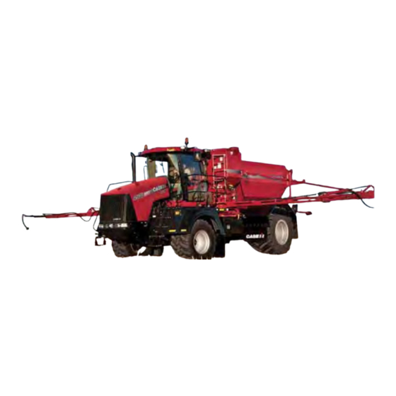
I ntroduction CHAPTER C h a p t e r 2 Congratulations on your purchase of the Steering Ready system! This system is designed to provide cutting- edge, hands-free steering of the machine via Global Positioning System (GPS) coordinates. This manual applies to the following machines: MAKE: Case IH MODEL: Titan 4030 and 4530 YEAR: 2013 &... -
Page 8: Recommendations
Chapter 2 Recommendations Raven Industries recommends the following best practices when installing or operating the SmarTrax system for the first time, at the start of the season, or when moving the SmarTrax system to another machine: • Install the GPS antenna in the recommended location. Refer to the following table for the machine-specific antenna mounting location. -
Page 9: Kit Contents
Introduction At Raven Industries, we strive to make your experience with our products as rewarding as possible. One way to improve this experience is to provide us with feedback on this manual. Your feedback will help shape the future of our product documentation and the overall service we provide. - Page 10 Chapter 2 SmarTrax Installation Kit (P/N 117-4001-127) TABLE 1. Picture Item Description Part Number Qty. Bracket - Node Mounting 107-0171-954 Bracket - Node Support 107-0171-960 Bracket - Node Mounting 107-0172-084 Assembly - SmarTrax Enable Switch 063-0172-470 Cable - SmarTrax Valve Harness 115-4001-002 Cable - SmarTrax Node Harness 115-4001-196...
- Page 11 Introduction SmarTrax Installation Kit (P/N 117-4001-127) TABLE 1. Picture Item Description Part Number Qty. Nut - 3/8”-16 312-1001-037 Nut - 3/8” Zinc Flanged Lock 312-1001-164 Nut - 5/16”-18 x 7/8” Hex 312-1001-169 Nut - 1/4”-20 Nylon Insert Lock 312-4000-057 Nut - M6 Lock 312-4000-207 Washer - 1/4”...
- Page 12 Chapter 2 Hydraulic Installation Kit (P/N 117-0199-023) TABLE 2. Picture Item Description Part Number Qty. Fitting - -8 ORFS M/M/F Swivel Run Tee 333-0012-028 Adapter Fitting - -6 ORFS M/F 90° Swivel Elbow 333-0012-065 Fitting - -8 ORFS M/F 90° Swivel Elbow 333-0012-067 Fitting - -6 ORFS (M) to -6 SAE O-Ring (M) 333-0012-084...
-
Page 13: Hydraulic System Installation
H ydraulic System CHAPTER C h a p t e r 3 Installation WARNING Hydraulics are under pressure. Care should always be taken with a system that has been pressurized. Before beginning the SmarTrax hydraulic installation, turn off the machine and relieve pressure by turning the steering wheel left and right. -
Page 14: Install Fittings In The Smartrax Valve
Chapter 3 NOTICE The appearance of the SmarTrax hydraulic valve may vary slightly from the images contained in this manual. However, the fittings, hose connections, and cable connections remain the same. Install Fittings in the SmarTrax Valve Before mounting the SmarTrax valve (P/N 063-0131-129) on the machine, install the proper fittings in the valve. -
Page 15: Mount The Smartrax Valve
Hydraulic System Installation Mount the SmarTrax Valve SmarTrax Valve Mounting Location FIGURE 2. Identify the valve mounting location under the hood, just in front of the steering orbital. Secure the SmarTrax valve (P/N 063-0131-129) to the hydraulic valve mounting bracket (P/N 107-0171- 907) using four 5/16”-18 x 7/8”... -
Page 16: Install The Left And Right Steering Hoses
Chapter 3 Install the Left and Right Steering Hoses Left Steering Hose Installed FIGURE 4. Disconnect the machine’s left steering hose from the steering orbital. Install a -8 ORFS M/M/F swivel run tee adapter fitting (P/N 333-0012-028) in the open port of the steering orbital. -
Page 17: Install The Pressure And Tank Hoses
Hydraulic System Installation Connect the machine’s right steering hose to the opposite end of the installed tee fitting. Install the 90° end of the supplied hydraulic hose (P/N 214-1000-663) on the 90° end of the installed tee fitting. Note: It may be necessary to install a -8 ORFS M/F 90° swivel elbow fitting (P/N 333-0012-067) on the tee fitting to achieve the connection. - Page 18 Chapter 3 Tank Hose Installed FIGURE 7. Tank Port Disconnect the machine’s tank hose from the steering orbital. Install a -8 ORFS M/M/F swivel run tee adapter fitting (P/N 333-0012-028) in the open port of the steering orbital. Connect the machine’s tank hose to the opposite end of the installed tee fitting. Install the 90°...
-
Page 19: Install The Load Sense Hoses
Hydraulic System Installation Install the Load Sense Hoses Load Sense Port on the Steering Orbital FIGURE 8. Disconnect the machine’s load sense hose from the steering orbital. SmarTrax Valve Load Sense Hose Connections FIGURE 9. LS STEER LSPV Connect the machine’s load sense hose to the fitting installed in Port LSPV on the SmarTrax valve. Install the straight end of the supplied hydraulic hose (P/N 214-1000-316) on the open port of the steering orbital. -
Page 20: Hydraulic Diagram
Chapter 3 Hydraulic Diagram Case IH Titan 4030 and 4530, Model Year 2013 & Newer SmarTrax™ Installation Manual... -
Page 21: Cab Component Installation
CHAPTER C h a p t e r 4 Installation Install the SmarTrax Node Note: The SmarTrax node (P/N 063-0173-228) is sold separately. Contact your local Raven dealer for ordering information. Node Mounting Locations Node Mounting FIGURE 1. Direction Arrows... -
Page 22: Install The Smartrax Node - Preferred Mounting Method
Chapter 4 • Securely fasten the node using bolts or screws through at least two of the three mounting holes. When mounted properly, the node should not become loose or rotate. Install the SmarTrax Node - Preferred Mounting Method Instructional Seat Mounting Screws FIGURE 2. - Page 23 Cab Component Installation Removing Instructional Seat Molding FIGURE 4. Plastic Molding Remove the plastic molding under the instructional seat by removing the nuts and bolts securing it. Node Mounted to Mounting Plate FIGURE 5. Mount the SmarTrax node (P/N 063-0173-228) to the node mounting bracket (P/N 107-0172-084) using three 3/8”-16 zinc flanged lock nuts (P/N 312-1001-164).
- Page 24 Chapter 4 Node Harness Installed on Node FIGURE 6. Install the two large, rectangular connectors of the node cable (P/N 115-4001-196) into the correct ports of the node, tightening the bolts on the harness connectors to secure the connections. Note: The connectors should be facing the window.
- Page 25 Cab Component Installation Convenience Tray Removed FIGURE 8. Remove the convenience tray from the right-rear corner of the cab. Locate the connectors labeled POWER GND PORT and PRODUCT CAN on the machine’s harness in the convenience tray compartment. Connect the machine’s POWER GND PORT connector to the mating 6-pin POWER connector on the node harness.
-
Page 26: Mount The Smartrax Node - Secondary Mounting Method
Chapter 4 Mount the SmarTrax Node - Secondary Mounting Method Node Mounting Location FIGURE 10. Identify the node mounting location on the bracket right side of the operator’s seat. Hole Drilled in Machine’s Bracket FIGURE 11. Align the hole in the node mounting bracket (P/N 107-0171-954) with the hole in the machine’s bracket. Using the node mounting bracket as a template, drill a second hole in the machine’s bracket. - Page 27 Cab Component Installation Node Mounting Bracket Installed FIGURE 12. Secure the node mounting bracket to the machine’s bracket using two 1/4”-20 x 1-1/4” hex bolts (P/N 311- 0050-106), two 1/4” flat washers (P/N 313-2300-009), and two 1/4”-20 nylon insert lock nuts (P/N 312-4000- 057).
- Page 28 Chapter 4 Node Support Bracket Secured to Node Mounting Bracket FIGURE 14. Position the node support bracket (P/N 107-0171-960) so that the hole aligns with the hole in the bottom node mounting tab. Secure the node support bracket to the node mounting bracket by inserting a 5/16"-18 x 7/8" hex bolt (P/N 311-0052-104) through both brackets and installing one 5/16”...
- Page 29 Cab Component Installation Node Harness Installed on Node FIGURE 16. Install the two large, rectangular connectors of the node harness (P/N 115-4001-196) into the correct ports of the node, tightening the bolts on the harness connectors to secure the connections. Node Harness Routing FIGURE 17.
-
Page 30: Install The Foot Switch
Chapter 4 Convenience Tray Removed FIGURE 18. Remove the convenience tray from the right-rear corner of the cab. Locate the connectors labeled POWER GND PORT and PRODUCT CAN on the machine’s harness in the convenience tray compartment. Connect the machine’s POWER GND PORT to the mating 6-pin POWER connector on the node harness. Remove the dust cap from the 4-pin PRODUCT CAN connector on the machine’s harness and connect it to the mating 4-pin CAN connector on the node harness. -
Page 31: Install The Valve Harness
Cab Component Installation Select a suitable location for the foot switch (P/N 063-0172-470) to be installed. Note: The foot switch should be installed in a location where the operator has easy access to it and is able to fully press the pedal. Using the holes in the foot switch as a template, drill holes in the floor of the cab. - Page 32 Chapter 4 Valve Harness Connected to Node Harness FIGURE 21. Connect the rectangular 12-pin connector on the valve harness into the mating connection of the node harness (P/N 115-4001-196). Connect the PSI connector to the transducer (P/N 422-0000-086) installed in Port PS of the SmarTrax valve (P/N 063-0131-139).
- Page 33 Cab Component Installation Valve Harness Wiring Diagram FIGURE 23. Manual No. 016-4001-127 Rev. B...
-
Page 34: System Diagrams
Chapter 4 System Diagrams Case IH Titan 4030 and 4530, Model Year 2013 & Newer SmarTrax™ Installation Manual... - Page 35 Cab Component Installation Manual No. 016-4001-127 Rev. B...
- Page 36 Chapter 4 Case IH Titan 4030 and 4530, Model Year 2013 & Newer SmarTrax™ Installation Manual...
-
Page 37: Startup Procedures
S tartup Procedures CHAPTER C h a p t e r 5 WARNING When starting the machine for the first time after installing SmarTrax, be sure that all persons stand clear in case a hose has not been properly tightened. WARNING Do not use hands to check for leaks. -
Page 38: Calibrate The Smartrax System
Chapter 5 Access the System Diagnostic screen by selecting the MACHINE TEST option on the Machine Type screen and turn the wheels using the Raven console. Note: If there are issues with the SmarTrax system, turn off the machine and correct them immediately. - Page 39 Index Cab Component Installation Installing the Foot Switch 25, 26 Installing the SmarTrax Node 17 Node Mounting Locations 17 Preferred Mounting Method 18 Secondary Mounting Method 22 Installing the Valve Harness 27 Hydraulic Installation Hydraulic Diagram 16 Installing Fittings in the SmarTrax Valve 10 Installing the Left and Right Steering Hoses 12 Installing the Load Sense Hoses 15 Installing the Pressure and Tank Hoses 13...
- Page 40 Index Case IH Titan 4030 and 4530, Model Year 2013 & Newer SmarTrax™ Installation Manual...
- Page 41 Bring the defective part and proof of purchase to your Raven dealer. If the dealer approves the warranty claim, the dealer will process the claim and send it to Raven Industries for final approval. The freight cost to Raven Industries will be the customer’s responsibility. The Return...
- Page 42 How Can I Get Service? Bring the defective part and proof of purchase to your Raven dealer. If the dealer approves the warranty claim, the dealer will process the claim and send it to Raven Industries for final approval.
- Page 44 Fax: 605-331-0426 www.ravenprecision.com www.ravenhelp.com Notice: This document and the information provided are the property of Raven Industries, Inc. and may only be used as authorized by Raven Industries, Inc. All rights reserved under copyright laws. ©Raven Industries, Inc. 2013, 2014...
Need help?
Do you have a question about the SmarTrax Case IH Titan 4030 and is the answer not in the manual?
Questions and answers