Table of Contents
Advertisement
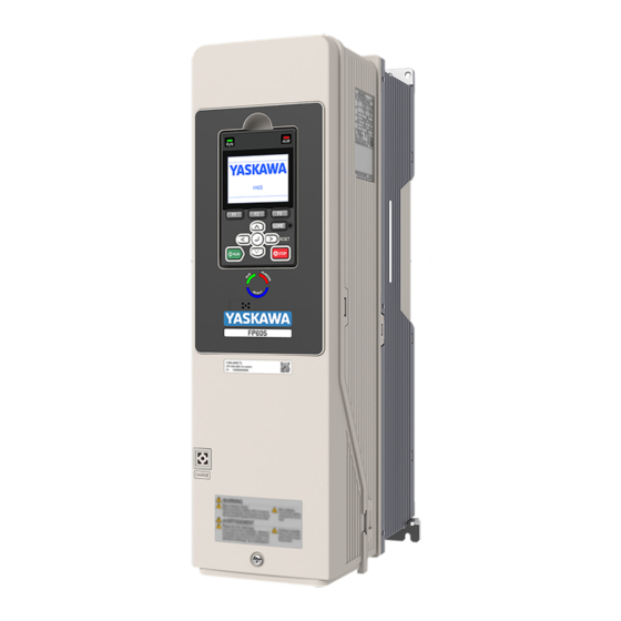
FP605 DRIVE
I N S T A L L A T I O N & P R I M A R Y O P E R A T I O N
A C D R I V E F O R I N D U S T R I A L F A N
A N D P U M P A P P L I C A T I O N S
C A T A L O G C O D E :
PDF
FP65Uxxxxxxx
yaskawa.com/TOEPC7106171F
C A P A C I T I E S :
208 V class: 2.2 to 110 kW (3 to 150 HP)
480 V class: 2.2 to 450 kW (3 to 600 HP)
D O C U M E N T N U M B E R : T O E P C 7 1 0 6 1 7 1 F
Advertisement
Table of Contents

Subscribe to Our Youtube Channel
Related Manuals for YASKAWA FP605


Summary of Contents for YASKAWA FP605
- Page 1 FP605 DRIVE I N S T A L L A T I O N & P R I M A R Y O P E R A T I O N A C D R I V E F O R I N D U S T R I A L F A N...
- Page 2 This Page Intentionally Blank YASKAWA TOEPC7106171FD FP605 DRIVE INSTALLATION & PRIMARY OPERATION...
-
Page 3: Table Of Contents
Main Circuit Terminal Block Wiring ......... . . 31 YASKAWA TOEPC7106171FD FP605 DRIVE INSTALLATION & PRIMARY OPERATION... - Page 4 E2-01: Motor Rated Current (FLA) ..........83 YASKAWA TOEPC7106171FD FP605 DRIVE INSTALLATION & PRIMARY OPERATION...
- Page 5 Revision History ........... . 128 YASKAWA TOEPC7106171FD FP605 DRIVE INSTALLATION & PRIMARY OPERATION...
-
Page 6: General Information
Yaskawa is not responsible for how our products are incorporated into the final system design. In all cases, Yaskawa products should not be incorporated into a product or design as the exclusive or sole safety control function. All control functions are designed to dynamically detect failures and operate safely without exception. - Page 7 Note: If you do not obey the safety messages in the manual, you are at risk for serious injury or death. Yaskawa is not responsible for injuries or damage to equipment if you ignore the safety messages.
- Page 8 Then check the wiring and peripheral device ratings to find the cause of the problem. If you do not know the cause of the problem, contact Yaskawa before you energize the drive or peripheral devices. If you do not fix the problem before you operate the drive or peripheral devices, it can cause serious injury or death.
-
Page 9: Exclusion Of Liability
• This product is not designed and manufactured for use in life-support machines or systems. • Contact a Yaskawa representative or your Yaskawa sales representative if you are considering the application of this product for special purposes, such as machines or systems used for passenger cars, medicine, airplanes and aerospace, nuclear power, electric power, or undersea relaying. -
Page 10: How To Read Catalog Codes
B - Weight H - Serial number C - Drive software version I - Lot number D - The address of the head office of Yaskawa J - Output specifications Electric Corporation K - Input specifications E - Accreditation standards... -
Page 11: Rated Output Current
Maximum Applicable Motor Output Rated Output Current Model kW (HP) 2.2 (3) 4005 4008 3.7 (5) 5.6 (7.5) 4011 7.5 (10) 4014 11.2 (15) 4021 15 (20) 4027 4034 18.6 (25) 22 (30) 4040 YASKAWA TOEPC7106171FD FP605 DRIVE INSTALLATION & PRIMARY OPERATION... -
Page 12: Common Drive Specifications
Parameter settings allow different limits in four quadrants in EZOLV control method. Torque Limits 0.0 s to 6000.0 s Accel/Decel Time The drive can set two pairs of different acceleration and deceleration times. YASKAWA TOEPC7106171FD FP605 DRIVE INSTALLATION & PRIMARY OPERATION... - Page 13 • You can use IP55/UL Type 12 drives at a maximum of 50 °C (122 °F) when you derate the output current. 95% RH or less Humidity Do not let condensation form on the drive. -20 °C to +70 °C (-4 °F to +158 °F) (short-term temperature during transportation) Storage Temperature YASKAWA TOEPC7106171FD FP605 DRIVE INSTALLATION & PRIMARY OPERATION...
-
Page 14: Area Of Use
Obey local laws and regulations when moving and installing this product. CAUTION Crush Hazard. Tighten terminal cover screws and hold the case safely when you move the drive. If the drive or covers fall, it can cause moderate injury. YASKAWA TOEPC7106171FD FP605 DRIVE INSTALLATION & PRIMARY OPERATION... -
Page 15: Using The Hanging Brackets To Move The Drive
When you install models 2011 to 2169 and 4005 to 4156 in an enclosure or when you install the drive with the heatsink external to the enclosure, set L8-35 = 0 [Installation Method Selection = IP20/UL Open Type]. YASKAWA TOEPC7106171FD FP605 DRIVE INSTALLATION & PRIMARY OPERATION... -
Page 16: Side-By-Side Installation
NOTICE Damage to Equipment. Do not remove the top protective cover of model 4065. If you remove the cover, the drive temperature will increase and it can cause damage to the drive. YASKAWA TOEPC7106171FD FP605 DRIVE INSTALLATION & PRIMARY OPERATION... -
Page 17: Installing More Than One Drive Adjacent To Each Other Without Derating
Figure 6.4 IP20/UL Type 1 Drives Installed Side-by-Side ■ Installing More than One Drive Adjacent to Each Other without Derating Use the clearances specified in Figure 6.5. Make sure that there is sufficient space. YASKAWA TOEPC7106171FD FP605 DRIVE INSTALLATION & PRIMARY OPERATION... -
Page 18: Remove The Top Protective Cover: 2011 To 2114, 4005 To 4052, And 4077 To 4124
Put the end of a straight-edge screwdriver into the small hole on the front edge of the top protective cover, then carefully apply pressure to remove the cover from the drive. Figure 6.6 Remove the Top Protective Cover (2011 to 2114, 4005 to 4052, and 4077 to 4124) YASKAWA TOEPC7106171FD FP605 DRIVE INSTALLATION & PRIMARY OPERATION... -
Page 19: Remove The Top Protective Cover: 2143, 2169, And 4156
Vdc. When all indicators are OFF, remove the covers before measuring for dangerous voltages to make sure that the drive is safe. If you do work on the drive when it is energized, it will cause serious injury or death from electrical shock. YASKAWA TOEPC7106171FD FP605 DRIVE INSTALLATION & PRIMARY OPERATION... - Page 20 • Make sure that the tabs on the sides of the front cover correctly click into the hook. • Tighten the screws to a tightening torque of 0.98 N∙m to 1.33 N∙m (8.67 lbf∙in to 11.77 lbf∙in). YASKAWA TOEPC7106171FD FP605 DRIVE INSTALLATION & PRIMARY OPERATION...
-
Page 21: Removing/Reattaching The Cover Using Procedure B
Crush Hazard. Loosen the cover screws. Do not fully remove them. If you fully remove the cover screws, the terminal cover can fall and cause moderate injury. Figure 6.12 Loosen the Terminal Cover Mounting Screws Pull the terminal cover away from the drive. Figure 6.13 Remove the Terminal Cover YASKAWA TOEPC7106171FD FP605 DRIVE INSTALLATION & PRIMARY OPERATION... - Page 22 Figure 6.16 Pull Forward to Remove the Front Cover Remove the front cover from the drive. Figure 6.17 Remove the Front Cover Reattach the Front Cover Wire the drive and other peripheral devices then reattach the front cover. YASKAWA TOEPC7106171FD FP605 DRIVE INSTALLATION & PRIMARY OPERATION...
-
Page 23: Removing/Reattaching The Cover Using Procedure C
Vdc. When all indicators are OFF, remove the covers before measuring for dangerous voltages to make sure that the drive is safe. If you do work on the drive when it is energized, it will cause serious injury or death from electrical shock. YASKAWA TOEPC7106171FD FP605 DRIVE INSTALLATION & PRIMARY OPERATION... - Page 24 Figure 6.21 Open the IP55/UL Type 12 Keypad Cover Door Remove the keypad from the drive. A - Keypad Figure 6.22 Remove the Keypad Loosen the front cover screw. Figure 6.23 Loosen the Front Cover Screw YASKAWA TOEPC7106171FD FP605 DRIVE INSTALLATION & PRIMARY OPERATION...
- Page 25 Open the IP55/UL Type 12 keypad cover door and reattach the keypad to its initial position, then close the door until the two tabs click into position. Figure 6.26 Reattach the Keypad and Close the Keypad Cover Door YASKAWA TOEPC7106171FD FP605 DRIVE INSTALLATION & PRIMARY OPERATION...
-
Page 26: Electrical Installation
Motor winding and insulation failure can occur. Note: Do not connect the AC control circuit ground to the drive enclosure. Incorrect ground wiring can cause the control circuit to operate incorrectly. YASKAWA TOEPC7106171FD FP605 DRIVE INSTALLATION & PRIMARY OPERATION... -
Page 27: Standard Drive Connection Diagram
7 Electrical Installation ■ Standard Drive Connection Diagram Figure 7.1 Standard Drive Connection Diagram YASKAWA TOEPC7106171FD FP605 DRIVE INSTALLATION & PRIMARY OPERATION... -
Page 28: Main Circuit Terminal Functions
*18 Disconnect the jumpers between H1 and HC and H2 and HC to use the Safe Disable input. ◆ Main Circuit Terminal Functions Refer to Table 7.1 for the functions of drive main circuit terminals. YASKAWA TOEPC7106171FD FP605 DRIVE INSTALLATION & PRIMARY OPERATION... -
Page 29: Motor And Main Circuit Connections
Electrical Shock Hazard. Do not connect terminals R/L1, S/L2, T/L3, U/T1, V/T2, W/T3, -, or +1 to the ground terminal. If you connect these terminals to earth ground, it can cause damage to the drive or serious injury or death. YASKAWA TOEPC7106171FD FP605 DRIVE INSTALLATION & PRIMARY OPERATION... -
Page 30: Wiring The Main Circuit And Motor
B - Connect to the drive ground terminal. E - Use R, S, T for input power supply. C - Ground the motor case. F - Input Protection (Fuses or Circuit Breakers) YASKAWA TOEPC7106171FD FP605 DRIVE INSTALLATION & PRIMARY OPERATION... -
Page 31: Main Circuit Terminal Block Wiring
Line voltage drop (V) = × wire resistance (Ω/km) × wiring distance (m) × motor rated current (A) × 10 Precautions during Wiring Use terminals +1 and - to connect a regenerative converter or regenerative unit. YASKAWA TOEPC7106171FD FP605 DRIVE INSTALLATION & PRIMARY OPERATION... - Page 32 (2.5 - 10) (13.5 - 15) 2024 14 - 8 1.5 - 1.7 -, +1 (2.5 - 10) (13.5 - 15) 14 - 8 2.0 - 2.5 (2.5 - 10) (17.7 - 22.1) YASKAWA TOEPC7106171FD FP605 DRIVE INSTALLATION & PRIMARY OPERATION...
- Page 33 (10 - 70) (47.8 - 53.1) 2114 8 - 2/0 5.4 - 6.0 -, +1 (10 - 70) (47.8 - 53.1) 8 - 2/0 9.0 - 11 (10 - 70) (79.7 - 97.4) YASKAWA TOEPC7106171FD FP605 DRIVE INSTALLATION & PRIMARY OPERATION...
- Page 34 AWG/kcmil values. Obey local safety regulations for wire sizes and make sure that the ferrule or crimp terminals are correct for your size. For IP20 protection, use wires that are in the range of applicable gauges. Remove insulation from the ends of wires to expose the length of wire shown. YASKAWA TOEPC7106171FD FP605 DRIVE INSTALLATION & PRIMARY OPERATION...
- Page 35 (2.5 - 10) (13.5 - 15) 4027 14 - 8 1.5 - 1.7 -, +1 (2.5 - 10) (13.5 - 15) 14 - 8 2.0 - 2.5 (2.5 - 10) (17.7 - 22.1) YASKAWA TOEPC7106171FD FP605 DRIVE INSTALLATION & PRIMARY OPERATION...
- Page 36 (10 - 70) (47.8 - 53.1) 4096 8 - 2/0 5.4 - 6.0 -, +1 (10 - 70) (47.8 - 53.1) 8 - 2/0 9.0 - 11 (10 - 70) (79.7 - 97.4) YASKAWA TOEPC7106171FD FP605 DRIVE INSTALLATION & PRIMARY OPERATION...
- Page 37 31.5 - 35 -, +1 300 × 2 (95 - 185 × 2P) (150 - 185 × 2P) (279 - 310) 1 - 350 32 - 40 (50 - 185) (283 - 354) YASKAWA TOEPC7106171FD FP605 DRIVE INSTALLATION & PRIMARY OPERATION...
-
Page 38: Main Circuit Terminal Block Wiring Procedure
Vdc. When all indicators are OFF, remove the covers before measuring for dangerous voltages to make sure that the drive is safe. If you do work on the drive when it is energized, it will cause serious injury or death from electrical shock. YASKAWA TOEPC7106171FD FP605 DRIVE INSTALLATION & PRIMARY OPERATION... - Page 39 High speeds can cause damage to the terminal screws. NOTICE Do not tighten the terminal screws at an angle of 5 degrees or more. Incorrect positioning can cause damage to the terminal screws. Figure 7.2 Permitted Angle YASKAWA TOEPC7106171FD FP605 DRIVE INSTALLATION & PRIMARY OPERATION...
- Page 40 • Users can purchase wiring tools from Yaskawa. Contact Yaskawa or your nearest sales representative for more information. • Wire gauges on existing drive models to be replaced may not match wire gauge ranges on new drives. Contact Yaskawa or your nearest sales representative for more information about the connection procedures.
-
Page 41: Wiring The Main Circuit Terminal Block Using Procedure A
• Install the included rubber grommets or use conduits to keep the IP20 protection level and to prevent damage to the wires. To comply with UL standards, you must use conduits for wiring. YASKAWA TOEPC7106171FD FP605 DRIVE INSTALLATION & PRIMARY OPERATION... -
Page 42: Wiring The Main Circuit Terminal Block Using Procedure B
Injury to Personnel. Carefully move the screwdriver to remove the knock-out holes. If you use too much pressure on the circular metal plates, they can eject and cause injury. Use a file to make the rough surface of the knock-out hole edge smooth. YASKAWA TOEPC7106171FD FP605 DRIVE INSTALLATION & PRIMARY OPERATION... - Page 43 • Install the included rubber grommets or use conduits to keep the IP20 protection level and to prevent damage to the wires. To comply with UL standards, you must use conduits for wiring. Align the closed-loop crimp terminals with the bolt holes on main circuit terminal block. Figure 7.11 Install the Electrical Wires YASKAWA TOEPC7106171FD FP605 DRIVE INSTALLATION & PRIMARY OPERATION...
-
Page 44: Wiring The Main Circuit Terminal Block Using Procedure C
WARNING Injury to Personnel. Carefully move the screwdriver to remove the knock-out holes. If you use too much pressure on the circular metal plates, they can eject and cause injury. YASKAWA TOEPC7106171FD FP605 DRIVE INSTALLATION & PRIMARY OPERATION... - Page 45 Install the included rubber grommets or use conduits to keep the IP20 protection level and to prevent damage to the wires. To comply with UL standards, you must use conduits for wiring. YASKAWA TOEPC7106171FD FP605 DRIVE INSTALLATION & PRIMARY OPERATION...
-
Page 46: Wiring The Main Circuit Terminal Block Using Procedure D
Remove the screws on the terminal block cover and pull the terminal block cover away from the drive. Pull the wiring cover away from the drive. Do not discard the wiring cover. A - Terminal block cover B - Wiring cover Figure 7.18 Remove the Wiring Cover YASKAWA TOEPC7106171FD FP605 DRIVE INSTALLATION & PRIMARY OPERATION... - Page 47 Check the signal from the wired terminal and use a diagonal-cutting pliers to remove areas of the wiring cover cutaway section. Cut the correct areas shown in Figure 7.22 for your wire gauges. YASKAWA TOEPC7106171FD FP605 DRIVE INSTALLATION & PRIMARY OPERATION...
-
Page 48: Wiring The Main Circuit Terminal Block Using Procedure E
• Remove sharp edges from the wiring cover cutaway section to prevent damage to the wires. • If you use the wiring cover correctly, but you use wires that are not specified by Yaskawa, the drive will not necessarily keep its IP20 protective level. -
Page 49: Wiring The Main Circuit Terminal Block Using Procedure F
When you use terminals - and +1 and these terminals have covers, remove them to install the wire. A - Bolt Figure 7.25 Remove the Terminal Block Bolts Put the ends of wires with closed-loop crimp terminals through the conduits. YASKAWA TOEPC7106171FD FP605 DRIVE INSTALLATION & PRIMARY OPERATION... - Page 50 • The knock-out holes for main circuit wiring do not have rubber grommets. Install the correct conduit to keep the IP55/UL Type 12 protection level. A - Rubber grommets YASKAWA TOEPC7106171FD FP605 DRIVE INSTALLATION & PRIMARY OPERATION...
-
Page 51: Keypad: Names And Functions
• LOCAL: Use the keypad to operate the drive. Use the keypad to enter Run/Stop commands and the frequency reference command. • REMOTE: Use the control circuit terminals or serial transmission to operate the drive. Use the frequency reference source entered in b1-01 and the Run command source selected in b1-02. YASKAWA TOEPC7106171FD FP605 DRIVE INSTALLATION & PRIMARY OPERATION... - Page 52 Accept Existing RUN Command], the drive can start suddenly. Before you change the control source, remove all personnel from the area around the drive, motor, and load. Sudden starts can cause serious injury or death. YASKAWA TOEPC7106171FD FP605 DRIVE INSTALLATION & PRIMARY OPERATION...
-
Page 53: Keypad Mode And Menu Displays
8 Keypad: Names and Functions ◆ Keypad Mode and Menu Displays Figure 8.2 Keypad Functions and Display Levels YASKAWA TOEPC7106171FD FP605 DRIVE INSTALLATION & PRIMARY OPERATION... -
Page 54: Led Status Ring
Sets data logs and backlight. Diagnostic Tools LED Status Ring The LED Status Ring on the drive cover shows the drive operating status. A - ALM/ERR C - RUN B - Ready YASKAWA TOEPC7106171FD FP605 DRIVE INSTALLATION & PRIMARY OPERATION... -
Page 55: Drive Start-Up Procedure
2. Confirm the correct drive installation environment. 3. Use the enclosed drilling template to install the drive. 4. Select the motor and power wires, wire strip length, crimp terminals, and branch circuit protection. YASKAWA TOEPC7106171FD FP605 DRIVE INSTALLATION & PRIMARY OPERATION... -
Page 56: Change Parameter Setting Values
• If [Home] is not shown above the , push (Back). Push (Menu). Push to select [Parameters], then push Push to select [C Tuning], then push Push to select [C1 Accel & Decel Time], then push YASKAWA TOEPC7106171FD FP605 DRIVE INSTALLATION & PRIMARY OPERATION... -
Page 57: Disable The Initial Setup Screen
• When the drive is in HOME Mode, the screen shows [Home] in the upper right-hand corner of the screen. • If the screen does not show [Home] for , push (Back), and then push to show [Home]. Push (Menu). Push to select [Initial Setup], then push YASKAWA TOEPC7106171FD FP605 DRIVE INSTALLATION & PRIMARY OPERATION... -
Page 58: Control Circuit Terminal Block Functions
Damage to Equipment. Do not energize and de-energize the drive more frequently than one time each 30 minutes. If you frequently energize and de-energize the drive, it can cause drive failure. ■ Input Terminals Refer to Table 10.1 for a list of input terminals and functions. YASKAWA TOEPC7106171FD FP605 DRIVE INSTALLATION & PRIMARY OPERATION... - Page 59 • 4 mA to 20 mA/100%, 0 mA to 20 mA/100% (input impedance: 250 Ω) Signal Ground for Multi-Function Analog Input Frequency reference common • 0 V Connecting shielded cable Frame Earth YASKAWA TOEPC7106171FD FP605 DRIVE INSTALLATION & PRIMARY OPERATION...
-
Page 60: Output Terminals
Note: (Zero Speed) Do not set functions that frequently switch ON/OFF to MFDO (M1 to M4) because this will decrease the performance life of the relay contacts. Yaskawa estimates switching life at MFDO 200,000 times (assumes 1 A, resistive load). -
Page 61: Control Circuit Terminal Configuration
Serial Communication MEMOBUS/Modbus network. Signal ground Option card ground ◆ Control Circuit Terminal Configuration The control circuit terminals are in the positions shown in Figure 10.1. Figure 10.1 Control Circuit Terminal Arrangement YASKAWA TOEPC7106171FD FP605 DRIVE INSTALLATION & PRIMARY OPERATION... -
Page 62: Control Circuit Wire Gauges And Tightening Torques
Stranded wire: 0.12 - 0.75 1.0 - 1.2 0.75 (26 - 18) 0.75 0.25 - 1.5 (8.85 - 10.62) (18) Solid wire: (18) (24 - 16) 0.2 - 1.5 (26 - 16) YASKAWA TOEPC7106171FD FP605 DRIVE INSTALLATION & PRIMARY OPERATION... -
Page 63: Wiring The Control Circuit Terminal
• Do not use control circuit wiring that is longer than 50 m (164 ft) to supply the frequency reference with an analog signal from a remote source. Wiring that is too long can cause unsatisfactory system performance. YASKAWA TOEPC7106171FD FP605 DRIVE INSTALLATION & PRIMARY OPERATION... - Page 64 Damage to Equipment. When you remove the cable sheath, also remove the shield. If you keep the shield on the wire, it can cause a short circuit and damage to the drive. YASKAWA TOEPC7106171FD FP605 DRIVE INSTALLATION & PRIMARY OPERATION...
-
Page 65: Switches And Jumpers On The Terminal Board
Switches and Jumpers on the Terminal Board The terminal board has switches to adapt the drive I/Os to the external control signals as shown in Figure 10.8. Set the switches to select the functions for each terminal. YASKAWA TOEPC7106171FD FP605 DRIVE INSTALLATION & PRIMARY OPERATION... -
Page 66: Control I/O Connections
Close the circuit between terminals SC-SP and SC-SN to set the sinking mode/sourcing mode and the internal/ external power supply for the MFDI terminals. The default setting for the drive is internal power supply sinking mode. YASKAWA TOEPC7106171FD FP605 DRIVE INSTALLATION & PRIMARY OPERATION... -
Page 67: Set Input Signals For Mfai Terminals A1 To A3
0: 0 V to 10 V/0% to 100% (input impedance: 20 kΩ) (Default) H3-05 2: 4 mA to 20 mA/0% to 100% (input impedance: 250 Ω) Current input 3: 0 mA to 20 mA/0% to 100% (input impedance: 250 Ω) YASKAWA TOEPC7106171FD FP605 DRIVE INSTALLATION & PRIMARY OPERATION... -
Page 68: Set Output Signals For Mfao Terminals Fm, Am
Figure 10.11 Location of DIP Switch S2 Table 10.10 RS-485 Communications Termination Resistor Setting DIP Switch S2 Description The built-in termination resistor is ON. OFF (Default) The built-in termination resistor is OFF. YASKAWA TOEPC7106171FD FP605 DRIVE INSTALLATION & PRIMARY OPERATION... -
Page 69: Drive Control And Programming
A1-02 = 8 Type T4-01 Application Conditions and Benefits [EZOLV] Set the motor parameters. Motor Parameter Setting Select this tuning mode after you replace the drive, motor, and motor cables. Line-to-Line Resistance YASKAWA TOEPC7106171FD FP605 DRIVE INSTALLATION & PRIMARY OPERATION... -
Page 70: Drive Parameters
OLV/PM OLV/PM EZOLV b1-02 Run Command Selection 1 (0181) Sets the input method for the Run command. 0 : Keypad 1 : Digital Input 2 : Memobus/Modbus Communications 3 : Option PCB YASKAWA TOEPC7106171FD FP605 DRIVE INSTALLATION & PRIMARY OPERATION... - Page 71 OLV/PM OLV/PM EZOLV E1-06 Base Frequency (0305) Sets the base frequency for the V/f pattern. OLV/PM OLV/PM EZOLV E1-09 Minimum Output Frequency (0308) Sets the minimum output frequency for the V/f pattern. YASKAWA TOEPC7106171FD FP605 DRIVE INSTALLATION & PRIMARY OPERATION...
- Page 72 Sets the bias of the analog signal input to MFAI terminal A2. OLV/PM OLV/PM EZOLV H3-13 Analog Input FilterTime Constant (041B) Sets the time constant for primary delay filters on MFAI terminals. YASKAWA TOEPC7106171FD FP605 DRIVE INSTALLATION & PRIMARY OPERATION...
- Page 73 5 : Overexcitation/High Flux 2 OLV/PM OLV/PM EZOLV o1-58 Motor Power Unit Selection (3125) Sets the setting unit for parameters that set the motor rated power. 0 : kW 1 : HP YASKAWA TOEPC7106171FD FP605 DRIVE INSTALLATION & PRIMARY OPERATION...
-
Page 74: Ul Standards
To comply with UL standards on drive models 2075 to 2396 and 4077 to 4720, use UL Listed closed-loop crimp terminals. Use the tools recommend by the terminal manufacturer to crimp the closed-loop crimp terminal. Yaskawa recommends closed-loop crimp terminals from PANDUIT Corp. - Page 75 LCA10-14-L P10-14R-L R/L1, S/L2, T/L3 F83-18 U/T1, V/T2, W/T3 F84-18 2046 -, +1 F84-18 LCA8-14-L P8-14R-Q S8-14R-Q R/L1, S/L2, T/L3 F85-18 U/T1, V/T2, W/T3 F85-18 2059 -, +1 F85-18 LCA6-14-L P6-14R-E S6-14R-E YASKAWA TOEPC7106171FD FP605 DRIVE INSTALLATION & PRIMARY OPERATION...
- Page 76 S2-12R-X LCA2-12-Q S2/0-76R-X R/L1, S/L2, T/L3 2/0 × 2 LCA2/0-12-X S2/0-12R-X S2/0-76R-X U/T1, V/T2, W/T3 2/0 × 2 LCA2/0-12-X 2273 S2/0-12R-X S3/0-76R-5 -, +1 4/0 × 2 LCA3/0-12-X S3/0-12R-5 LCA2-12-Q P2-12R-X S2-12R-X YASKAWA TOEPC7106171FD FP605 DRIVE INSTALLATION & PRIMARY OPERATION...
- Page 77 -, +1 F82-10 LCA10-14-L P10-14R-L R/L1, S/L2, T/L3 F82-10 U/T1, V/T2, W/T3 F83-12 4027 -, +1 F83-12 LCA10-14-L P10-14R-L R/L1, S/L2, T/L3 F83-12 U/T1, V/T2, W/T3 F83-12 4034 -, +1 F83-12 LCA10-14-L P10-14R-L YASKAWA TOEPC7106171FD FP605 DRIVE INSTALLATION & PRIMARY OPERATION...
- Page 78 3 or 2 P2-12R-X S2-12R-X LCA2-12-Q R/L1, S/L2, T/L3 1/0 × 2 LCA1/0-12-X S1/0-12R-X U/T1, V/T2, W/T3 1/0 × 2 LCA1/0-12-X S1/0-12R-X S3/0-76R-5 4240 -, +1 3/0 × 2 LCA3/0-12-X S3/0-12R-5 LCA2-12-Q P2-12R-X S2-12R-X YASKAWA TOEPC7106171FD FP605 DRIVE INSTALLATION & PRIMARY OPERATION...
-
Page 79: Short Circuit Protection Requirements For Ul Listing
If you do not know the cause of the problem, contact Yaskawa before you energize the drive or peripheral devices. If you do not fix the problem before you operate the drive or peripheral devices, it can cause serious injury or death. -
Page 80: Ul Compliance
Electric Code Compliance The user must provide short circuit protection to protect input branch circuits as specified by the National Electric Code (NEC), the Canadian Electric Code, Part 1 (CEC), and local codes. YASKAWA TOEPC7106171FD FP605 DRIVE INSTALLATION & PRIMARY OPERATION... - Page 81 12 UL Standards Required Short Circuit Protection Table 12.2 Required Short Circuit Protection for FP605 AC Drives (240 V Class) Drive Mounted in Supplemental Enclosure Drive Mounted without Supplemental Enclosure Any Size Protected Enclosure Restricted Size Protected Enclosure (Using Type 1 Kit)
- Page 82 12 UL Standards Table 12.3 Required Short Circuit Protection for FP605 AC Drives (480 V Class) Drive Mounted in Supplemental Enclosure Drive Mounted without Supplemental Enclosure Any Size Protected Enclosure Restricted Size Protected Enclosure (Using Type 1 Kit) (Ventilated or Non-Ventilated)
-
Page 83: Low Voltage Wiring For Control Circuit Terminals
You must provide low voltage wiring as specified by the National Electric Code (NEC), the Canadian Electric Code, Part I (CEC), and local codes. Yaskawa recommends the NEC class 1 circuit conductor. Use the UL Listed class 2 power supply for external power supply. -
Page 84: E9-06: Motor Rated Current (Fla)
Disable motor protection when motor overload protection is not necessary or when the drive is operating more than one motor. Refer to Figure 12.2 for an example of the circuit configuration to connect more than one motor to one drive. YASKAWA TOEPC7106171FD FP605 DRIVE INSTALLATION & PRIMARY OPERATION... - Page 85 The motor operates continuously at 10% to 100% base during continuous operation in the low speed range (10% frequency. Operating slower than 10% speed at 100% load base frequency). will cause motor overload. YASKAWA TOEPC7106171FD FP605 DRIVE INSTALLATION & PRIMARY OPERATION...
- Page 86 Operating slower than 0.2% speed at 100% load will base frequency). cause motor overload. 6 : Variable Torque (50Hz) Use this setting for general-purpose motors with a 50 Hz base frequency. YASKAWA TOEPC7106171FD FP605 DRIVE INSTALLATION & PRIMARY OPERATION...
-
Page 87: L1-02: Motor Overload Protection Time
• Hot start Shows the motor protection operation time characteristics when overload occurs from continuous operation below the motor rated current. Figure 12.3 Protection Operation Time for a General-purpose Motor at Rated Output Frequency YASKAWA TOEPC7106171FD FP605 DRIVE INSTALLATION & PRIMARY OPERATION... -
Page 88: L1-03: Motor Thermistor Oh Alarm Select
European Union standards include standards for electrical appliances (Low Voltage Directive), standards for electrical noise (EMC Directive), and standards for machinery (Machinery Directive). This product displays the CE Mark in accordance with the Low Voltage Directive, the EMC Directive, and the Machinery Directive. YASKAWA TOEPC7106171FD FP605 DRIVE INSTALLATION & PRIMARY OPERATION... -
Page 89: Eu Declaration Of Conformity
Go to www.yaskawa.com Declaration of Conformity. Yaskawa declares that this product complies with the following directives and standards at our sole responsibility. ◆ CE Low Voltage Directive Compliance It has been confirmed that this product complies with the CE Low Voltage Directive by conducting a test according to IEC/EN 61800-5-1. - Page 90 For circuit protection, the main circuit is separated from the surface case that can touch the main circuit. To comply with LVD standard requirement, set L8-05 = 1 [Input Phase Loss Protection Sel = Enabled] to protect the drive from the high current caused by Input Phase Loss condition. YASKAWA TOEPC7106171FD FP605 DRIVE INSTALLATION & PRIMARY OPERATION...
-
Page 91: Main Circuit Wire Gauges And Tightening Torques
Then check the wiring and peripheral device ratings to find the cause of the problem. If you do not know the cause of the problem, contact Yaskawa before you energize the drive or peripheral devices. If you do not fix the problem before you operate the drive or peripheral devices, it can cause serious injury or death. - Page 92 Drive Model Manufacturer: Mitsubishi Electric 4005 NV32-SV 4008 NV32-SV 4011 NV32-SV 4014 NV32-SV 4021 NV63-SV 4027 NV63-SV 4034 NV63-SV 4040 NV125-SV 4052 NV125-SV 4065 NV125-SV 4077 NV250-SV 4096 NV250-SV 4124 NV250-SV 4156 NV400-SEW YASKAWA TOEPC7106171FD FP605 DRIVE INSTALLATION & PRIMARY OPERATION...
-
Page 93: Emc Directive
• Keep the grounding wire as short as possible. Use a cable clamp to ground the motor cable to the metal plate. Note: Make sure that the protective ground wire complies with technical specifications and local safety standards. YASKAWA TOEPC7106171FD FP605 DRIVE INSTALLATION & PRIMARY OPERATION... - Page 94 13 European Standards A - Braided shield cable C - Cable clamp (conductive) B - Metal plate Figure 13.4 Ground the shield YASKAWA TOEPC7106171FD FP605 DRIVE INSTALLATION & PRIMARY OPERATION...
- Page 95 Electrical Shock Hazard. Ground the neutral point on the power supply of the drives to comply with the EMC Directive before you turn on the EMC filter. If you turn ON the EMC filter, but you do not ground the neutral point, it can cause serious injury or death. YASKAWA TOEPC7106171FD FP605 DRIVE INSTALLATION & PRIMARY OPERATION...
- Page 96 EMC filter, it will cause damage to the drive. Table 13.6 shows asymmetric grounding networks. Table 13.6 Asymmetric Grounding Type of Grounding Diagram Grounded at the corner of the delta connection Grounded at the middle of the side YASKAWA TOEPC7106171FD FP605 DRIVE INSTALLATION & PRIMARY OPERATION...
- Page 97 To comply with IEC61800-3 on drive models 2xxxA and 4xxxA with no built-in EMC filter, turn on the EMC filter switch on the left side. Figure 13.7 EMC Filter Switch Location 1 YASKAWA TOEPC7106171FD FP605 DRIVE INSTALLATION & PRIMARY OPERATION...
- Page 98 To comply with IEC61800-3 on drive models 2xxxA and 4xxxA with no built-in EMC filter, turn on the EMC filter switch on the right side. Figure 13.10 EMC Filter Switch Location 4 YASKAWA TOEPC7106171FD FP605 DRIVE INSTALLATION & PRIMARY OPERATION...
-
Page 99: Install The External Emc Noise Filter
Drive models 2xxxA and 4xxxA must meet conditions in this section to comply with IEC/EN 61800-3. Connect an EMC noise filter that complies with European standards as specified by Yaskawa to the input side External EMC Noise Filter Selection on page 102 (primary side). - Page 100 Make sure that the protective ground wire complies with technical specifications and local safety standards. A - Braided shield cable C - Cable clamp (conductive) B - Metal plate Figure 13.13 Ground the Shield YASKAWA TOEPC7106171FD FP605 DRIVE INSTALLATION & PRIMARY OPERATION...
- Page 101 C - Metal plate H - Cable clamp D - Drive I - Grounding wire E - Ground the shield. J - EMC noise filter Figure 13.14 EMC Noise Filter and Drive Installation Procedure YASKAWA TOEPC7106171FD FP605 DRIVE INSTALLATION & PRIMARY OPERATION...
- Page 102 Table 13.10 External EMC Noise Filter for Three-Phase 480 V Class Model EMC Noise Filter Model Quantity Manufacturer B84743A0300R176 4180 B84743A0300R176 4240 4302 B84743A0300R176 B84743B0410S176 4361 B84743B0410S176 4414 B84743A0660S176 4477 B84743A0660S176 4515 4590 B84743A0660S176 B84743A1200S176 4720 YASKAWA TOEPC7106171FD FP605 DRIVE INSTALLATION & PRIMARY OPERATION...
-
Page 103: China Rohs Compliance
This product complies with EU RoHS directives. In this table, "×" indicates that hazardous substances that are exempt from EU RoHS directives are contained. 对应中国RoHS指令 图 15.1 中国RoHS标志 中国RoHS标志依据2016年1月26日公布的《电器电子产品有害物质限制使用管理办法》,以及《电子电气产品有害物 质限制使用标识要求》(SJ/T 11364-2014)作成。电子电气产品中特定6种有害物质的含量超过规定值时,应标识此标 志。中间的数字为在中国生产销售以及进口的电子电气产品的环保使用期限(年限)。电子电气产品的环保使用期限从 生产日期算起。在期限内,正常使用产品的过程中,不会有特定的6种有害物质外泄进而对环境、人和财产造成深刻影 响。 本产品的环保使用期限为15年。但需要注意的是环保使用期限并非产品的质量保证期限。 YASKAWA TOEPC7106171FD FP605 DRIVE INSTALLATION & PRIMARY OPERATION... -
Page 104: 本产品中含有有害物质的信息
Figure 16.1 TUV Mark The TUV mark identifies that the product complies with the safety standards. This section gives precautions to support the Safe Disable input. Contact Yaskawa for more information. The safety function complies with the standards shown in Table 16.1. -
Page 105: Safe Disable Specifications
Sudden Movement Hazard. To use the Safe Disable inputs, remove the jumpers between terminals H1-HC and H2-HC. If the Safe Disable circuit does not work correctly, it can cause serious injury or death. YASKAWA TOEPC7106171FD FP605 DRIVE INSTALLATION & PRIMARY OPERATION... -
Page 106: Using The Safe Disable Function
■ Enabling and Disabling the Drive Output (“Safe Torque Off”) Refer to Figure 16.3 for an example of drive operation when the drive changes from “Safe Torque Off” status to usual operation. YASKAWA TOEPC7106171FD FP605 DRIVE INSTALLATION & PRIMARY OPERATION... -
Page 107: Safe Disable Monitor Output Function And Keypad Display
MFDO terminals. If there is damage to the Safe Disable circuit, a controller (PLC or safety relay) must read this signal as an input signal to hold the “Safe Torque Off” status. This YASKAWA TOEPC7106171FD FP605 DRIVE INSTALLATION & PRIMARY OPERATION... -
Page 108: Validating The Safe Disable Function
Table 16.3. Seismic Standards The Yaskawa drives in this manual are capable of structurally and operationally withstanding the seismic response criteria as defined in the International Building Code (IBC), ASCE7, and California Department of Health Care Access and Information (HCAI). -
Page 109: Disposal Instructions
• Customers are responsible for microSD card data protection. PC functions that format and delete the data may not be sufficient to fully erase the microSD card data. Yaskawa recommends that customers physically destroy the microSD card in a shredder or use data wipe software to fully erase the card. -
Page 110: Troubleshooting
Option Communication Error The drive did not receive a signal from the controller. Correct wiring errors. The communications cable wiring is incorrect. Correct wiring errors. Modbus Communication Error YASKAWA TOEPC7106171FD FP605 DRIVE INSTALLATION & PRIMARY OPERATION... - Page 111 There was a problem with the drive hardware. Replace the control board or the drive. For information about replacing the control board, contact Yaskawa or your nearest sales representative. The feedback level is more than the level set in Y1-11 •...
- Page 112 U/T1, V/T2, and W/T3. drive. • If there is a short circuit, contact Yaskawa or your nearest sales representative. The acceleration time is too short. • Calculate the torque necessary during acceleration related to the load inertia and the specified acceleration time.
- Page 113 The same option cards or the same type of option Connect the option card to the correct connector. oFA02 Duplicate Options cards are connected to connectors CN5-A and B. YASKAWA TOEPC7106171FD FP605 DRIVE INSTALLATION & PRIMARY OPERATION...
- Page 114 If E1-08 and E1-10 are set too low, the overload tolerance will decrease at low speeds. Motor Overload The load is too heavy. Decrease the load. Note: Reset oL1 when U4-16 [Motor oL1 Level] < 100. YASKAWA TOEPC7106171FD FP605 DRIVE INSTALLATION & PRIMARY OPERATION...
- Page 115 • Decrease the value set in C6-02 [Carrier Frequency Selection]. The torque compensation gain is too large. Decrease the value set in C4-01 [Torque Compensation Gain] to make sure that the motor does not stall. YASKAWA TOEPC7106171FD FP605 DRIVE INSTALLATION & PRIMARY OPERATION...
- Page 116 The load inertia is set incorrectly. • Examine the load inertia settings with KEB, overvoltage suppression, or stall prevention during deceleration. • Adjust L3-25 [Load Inertia Ratio] to align with the qualities of the machine. YASKAWA TOEPC7106171FD FP605 DRIVE INSTALLATION & PRIMARY OPERATION...
- Page 117 Example: There is a broken pulley belt. A fault occurred on the machine. Examine the machine and remove the cause of the fault. Undertorque Detection 2 Example: There is a broken pulley belt. YASKAWA TOEPC7106171FD FP605 DRIVE INSTALLATION & PRIMARY OPERATION...
-
Page 118: Minor Faults/Alarms
If U4-06 is more than 90%, replace the board or the drive. For information about replacing the board, contact Yaskawa or your nearest sales representative. Air inside the drive is too hot. - Page 119 Examine the controller and remove the cause of the problem. communication problem. The drive received a fault reset command when a Run Turn off the Run command then de-energize and re-energize the CrST Cannot Reset command was active. drive. YASKAWA TOEPC7106171FD FP605 DRIVE INSTALLATION & PRIMARY OPERATION...
- Page 120 Y4-12 [Thrust Frequency] in these conditions: • The drive is not in PI Mode • The drive is running • Thrust is enabled (Y4-11 [Thrust Acceleration Time] > 0.00 and Y4-12 > Y1-06 [Minimum Speed]) YASKAWA TOEPC7106171FD FP605 DRIVE INSTALLATION & PRIMARY OPERATION...
- Page 121 LT-2 Capacitor Maintenance Time are at 90% of their performance life estimate. replacing the control board, contact Yaskawa or your nearest sales representative. The soft charge bypass relay is at 90% of its Replace the control board or the drive. For information about...
- Page 122 • Examine the input power for problems. • Re-energize the drive. • If the alarm stays, replace the circuit board or the drive. Contact Yaskawa or your nearest sales representative for more information. YASKAWA TOEPC7106171FD FP605 DRIVE INSTALLATION & PRIMARY OPERATION...
-
Page 123: Parameter Setting Errors
• When the Safe Disable function is not in use, use a jumper to connect terminals H1-HC and H2-HC. There is internal damage to the two Safe Disable Replace the board or the drive. Contact Yaskawa or your nearest channels. sales representative to replace the board. -
Page 124: Auto-Tuning Errors
Find and repair the cause of the error and do Auto-Tuning again, or set the motor parameters manually. You can use the drive in the application if you cannot find the cause of the Endx error. YASKAWA TOEPC7106171FD FP605 DRIVE INSTALLATION & PRIMARY OPERATION... - Page 125 Examine and repair motor wiring. Er-12 Current Detection Error V/T2, W/T3) The motor rated current value is incorrect. Correctly set the rated current indicated on the motor nameplate and Er-13 Leakage Inductance Error do Auto-Tuning again. YASKAWA TOEPC7106171FD FP605 DRIVE INSTALLATION & PRIMARY OPERATION...
-
Page 126: Backup Function Operating Mode Display And Errors
Note: If the drive detects Er-25 after you do Stationary Auto-Tuning, it is possible that the motor cannot use high frequency injection. For more information, contact Yaskawa or your nearest sales representative. ◆ Backup Function Operating Mode Display and Errors ■... - Page 127 The parameters that are backed up in the keypad and Restore or backup the parameter again. vFyE Parameters do not Match the parameters in the drive are not the same. Verify the parameters. YASKAWA TOEPC7106171FD FP605 DRIVE INSTALLATION & PRIMARY OPERATION...
-
Page 128: Revision History
Revision: Reviewed and corrected entire documentation. Addition: December 2021 • IP55/UL Type 12 Heatsink External Mounting type added along with corresponding data. • C2 built-in EMC filter type added along with corresponding data. May 2021 First Edition YASKAWA TOEPC7106171FD FP605 DRIVE INSTALLATION & PRIMARY OPERATION... - Page 129 YASKAWA TOEPC7106171FD FP605 DRIVE INSTALLATION & PRIMARY OPERATION...
- Page 130 Regulations. Therefore, be sure to follow all procedures and submit all relevant documentation according to any and all rules, regulations and laws that may apply. Specifications are subject to change without notice for ongoing product modifications and improvements. Original instructions. © 2021 YASKAWA Electric Corporation TOEPC7106171F Revision: D <3>-0 October 2022...
Need help?
Do you have a question about the FP605 and is the answer not in the manual?
Questions and answers