Table of Contents
Advertisement
Quick Links
GA800 DRIVE
I N S T A L L A T I O N & P R I M A R Y O P E R A T I O N
A C D R I V E F O R I N D U S T R I A L A P P L I C A T I O N S
C A T A L O G C O D E :
PDF
GA80Uxxxxxxxx
yaskawa.com/TOEPC71061737
C A P A C I T I E S :
Three-Phase 200 V Class: 1 to 150 HP
Three-Phase 400 V Class: 1 to 1000 HP
6-Phase/12-Pulse 400 V Class: 75 to 600 HP
D O C U M E N T N U M B E R : T O E P C 7 1 0 6 1 7 3 7
Advertisement
Table of Contents

Subscribe to Our Youtube Channel
Related Manuals for YASKAWA GA80U Series


Summary of Contents for YASKAWA GA80U Series
- Page 1 A C D R I V E F O R I N D U S T R I A L A P P L I C A T I O N S C A T A L O G C O D E : GA80Uxxxxxxxx yaskawa.com/TOEPC71061737 C A P A C I T I E S : Three-Phase 200 V Class: 1 to 150 HP...
- Page 2 This Page Intentionally Blank YASKAWA TOEPC71061737D GA800 DRIVE INSTALLATION & PRIMARY OPERATION...
-
Page 3: Table Of Contents
Main Circuit Terminal Block Wiring Procedure........55 YASKAWA TOEPC71061737D GA800 DRIVE INSTALLATION & PRIMARY OPERATION... - Page 4 E5-03: PM Motor Rated Current (FLA) ......... . . 102 YASKAWA TOEPC71061737D GA800 DRIVE INSTALLATION & PRIMARY OPERATION...
- Page 5 Revision History ........... . 166 YASKAWA TOEPC71061737D GA800 DRIVE INSTALLATION & PRIMARY OPERATION...
-
Page 6: General Information
Be sure to always use the latest version of this manual. Use this manual to correctly install, wire, set, and operate this product. Users can download additional manuals for this product from the Yaskawa documentation website printed on the back cover. -
Page 7: Safety
Electrical Shock Hazard. Do not modify the drive body or drive circuitry. Modifications to drive body and circuitry can cause serious injury or death, will cause damage to the drive, and will void the warranty. Yaskawa is not responsible for modifications of the product made by the user. - Page 8 Then check the wiring and peripheral device ratings to find the cause of the problem. If you do not know the cause of the problem, contact Yaskawa before you energize the drive or peripheral devices. If you do not fix the problem before you operate the drive or peripheral devices, it can cause serious injury or death.
-
Page 9: Exclusion Of Liability
2. Examine the catalog code to make sure that you received the correct model. Examine the catalog code in the “C/ C” section of the drive nameplate to make sure that you received the correct model. 3. Contact your supplier or Yaskawa sales office if you received an incorrect drive model or if the drive does not operate correctly. -
Page 10: How To Read The Catalog Code
The software version for 6-Phase/12-Pulse drives is PRG: 09015 and later. The “PRG” column on the nameplate on the right side of the drive identifies the software version. You can also use U1-25 [SoftwareNumber Flashr] to identify the software version. YASKAWA TOEPC71061737D GA800 DRIVE INSTALLATION & PRIMARY OPERATION... -
Page 11: Rated Output Current
5.5 (7.5) 2021 5.5 (7.5) 7.5 (10) 2030 7.5 (10) 11 (15) 2042 11 (15) 15 (20) 2056 2070 15 (20) 18.5 (25) 18.5 (25) 22 (30) 2082 22 (30) 30 (40) 2110 YASKAWA TOEPC71061737D GA800 DRIVE INSTALLATION & PRIMARY OPERATION... - Page 12 220 (300) 4414 220 (300) 260 (350) 4477 260 (350) 300 (400) 4568 300 (400) 335 (450) 4605 335 (450) 370 (500) 4720 370 (500) 450 (600) 4810 450 (600) 525 (700) YASKAWA TOEPC71061737D GA800 DRIVE INSTALLATION & PRIMARY OPERATION...
-
Page 13: Drive Specifications
• Models 4477 to 4720, and T477 to T720 HD: 2 kHz without derating the drive capacity. ND: 2 kHz without derating the drive capacity. Derate the drive capacity to use values to 5 kHz maximum. YASKAWA TOEPC71061737D GA800 DRIVE INSTALLATION & PRIMARY OPERATION... - Page 14 –CLV –AOLV –AOLV/PM –CLV/PM • Set n8-57 = 1 [HFI Overlap Selection = Enabled] for this starting torque in AOLV/PM. When you use a non-Yaskawa PM motor, do Rotational Auto- Tuning. • V/f: 1:40 • CL-V/f: 1:40 • OLV: 1:200 •...
- Page 15 DC Bus Charge LED Charge LED illuminates when DC bus voltage is more than 50 V. Models 2004 to 2138 and 4002 to 4168 have a braking transistor. Braking Transistor DC Link Choke Models 2110 to 2415 and 4060 to 4H12 have a DC link choke. YASKAWA TOEPC71061737D GA800 DRIVE INSTALLATION & PRIMARY OPERATION...
- Page 16 • When you install the drive between 2000 m to 4000 m (6562 ft to 13123 ft) and ground the neutral point on the power supply. Contact Yaskawa or your nearest sales representative if you will not ground the neutral point.
-
Page 17: Area Of Use
TOEPC71061779) and the Quick Setup Procedures (document numbers TOEPC71061780 and TOEPC71061781). For dimensions and installation instructions for other external heatsink installations, refer to the External Heatsink Installation Kit Instruction Manual (document number TOEPC72060003). For product weights, refer to the drive nameplate. YASKAWA TOEPC71061737D GA800 DRIVE INSTALLATION & PRIMARY OPERATION... - Page 18 (10.24) (8.31) (4.02) (4.02) (9.76) (0.24) 4031 - 4038 (7.09) (11.81) (7.95) (5.51) (5.51) (11.18) (0.32) 4044 (8.66) (13.78) (8.94) (7.56) (7.56) (13.19) (0.32) 4060 (8.66) (13.78) (9.69) (7.56) (7.56) (13.19) (0.32) YASKAWA TOEPC71061737D GA800 DRIVE INSTALLATION & PRIMARY OPERATION...
- Page 19 Dimensions mm (in) Model 17.5 4075 (9.45) (15.75) (11.02) (7.68) (7.32) (14.76) (0.69) 4089 - 4103 (10.04) (17.72) (11.02) (6.69) (6.50) (16.69) (0.63) 17.5 4140 - 4168 (10.39) (21.38) (13.19) (7.48) (7.17) (20.31) (0.69) YASKAWA TOEPC71061737D GA800 DRIVE INSTALLATION & PRIMARY OPERATION...
- Page 20 4208 - 4302 (12.28) (27.56) (16.54) (8.58) (8.58) (25.94) (1.10) 4371 - 4414 (17.32) (31.50) (18.58) (14.57) (14.57) (29.80) (1.10) 1136 1093 25.5 4477 - 4720 (20.08) (44.72) (18.90) (17.72) (17.72) (43.03) (1.00) YASKAWA TOEPC71061737D GA800 DRIVE INSTALLATION & PRIMARY OPERATION...
-
Page 21: Moving The Drive
Use the hanging brackets attached to the drive to temporarily lift the drive when you install the drive to a control panel or wall or when you replace the drive. Do not let the drive stay vertically or horizontally suspended or move the drive over a long distance while it is suspended. YASKAWA TOEPC71061737D GA800 DRIVE INSTALLATION & PRIMARY OPERATION... -
Page 22: Installation Position And Clearances
Installation Position and Clearances Install the drive vertically for sufficient airflow to cool the drive. Note: Contact Yaskawa or a Yaskawa representative for more information about installing drive models on their side. Figure 6.1 Installation Orientation ■ Install Single Drive Use the clearances specified in Figure 6.2... -
Page 23: Removing/Reattaching Covers
This section gives information about how to remove and reattach the front cover and terminal cover for wiring and inspection. Different drive models have different procedures to remove and reattach the covers. Refer to Table 6.8 for more information. YASKAWA TOEPC71061737D GA800 DRIVE INSTALLATION & PRIMARY OPERATION... -
Page 24: Removing/Reattaching The Cover Using Procedure A
Figure 6.6 Loosen the Front Cover Screws Push on the tab in the side of the front cover then pull the front cover forward to remove it from the drive. Figure 6.7 Remove the Front Cover YASKAWA TOEPC71061737D GA800 DRIVE INSTALLATION & PRIMARY OPERATION... -
Page 25: Removing/Reattaching The Cover Using Procedure B
A - Keypad C - Connector holder B - Keypad connector Figure 6.9 Remove the Terminal Cover, Keypad, and Keypad Connector Loosen the front cover screws. Figure 6.10 Loosen the Front Cover Screws YASKAWA TOEPC71061737D GA800 DRIVE INSTALLATION & PRIMARY OPERATION... - Page 26 Move the front cover until it clicks into position while pushing on the hooks on the left and right sides of the front cover. Note: Make sure that you do not pinch wires or signal lines between the front cover and the drive before you reattach the cover. YASKAWA TOEPC71061737D GA800 DRIVE INSTALLATION & PRIMARY OPERATION...
- Page 27 –Models 4208 to 4675: 0.98 N∙m to 1.33 N∙m (8.67 lbf∙in to 11.77 lbf∙in) –Models 4810 to 4H12: 1.96 N∙m to 2.53 N∙m (17.35 lbf∙in to 22.39 lbf∙in) –Models T208 to T720: 0.98 N∙m to 1.33 N∙m (8.67 lbf∙in to 11.77 lbf∙in) YASKAWA TOEPC71061737D GA800 DRIVE INSTALLATION & PRIMARY OPERATION...
-
Page 28: Electrical Installation
Motor winding and insulation failure can occur. Note: Do not connect the AC control circuit ground to the drive enclosure. Failure to obey can cause incorrect control circuit operation. YASKAWA TOEPC71061737D GA800 DRIVE INSTALLATION & PRIMARY OPERATION... -
Page 29: Standard Drive Connection Diagram
L5-02 = 1 [Fault Contact at Restart Select = Always Active] to de-energize the drive. Be careful when you use a cut-off sequence. The default setting for L5-02 is 0 [Active Only when Not Restarting]. YASKAWA TOEPC71061737D GA800 DRIVE INSTALLATION & PRIMARY OPERATION... - Page 30 A junction terminal is necessary to connect wires that are less than the applicable gauge to the drive. Contact Yaskawa or your nearest sales representative for more information about selection and installation of the junction terminal.
- Page 31 7 Electrical Installation *22 Use only Sourcing Mode for Safe Disable input. *23 Disconnect the wire jumpers between H1 and HC and H2 and HC to use the Safe Disable input. YASKAWA TOEPC71061737D GA800 DRIVE INSTALLATION & PRIMARY OPERATION...
-
Page 32: Standard Connection Diagram For 6-Phase/12-Pulse Drives
7 Electrical Installation ■ Standard Connection Diagram for 6-Phase/12-Pulse Drives Figure 7.2 Standard Drive Connection Diagram: 6-Phase/12-Pulse Drives YASKAWA TOEPC71061737D GA800 DRIVE INSTALLATION & PRIMARY OPERATION... -
Page 33: Main Circuit Terminal Functions
A junction terminal is necessary to connect wires that are less than the applicable gauge to the drive. Contact Yaskawa or your nearest sales representative for more information about selection and installation of the junction terminal. -
Page 34: Motor And Main Circuit Connections
Electrical Shock Hazard. Do not connect terminals R/L1, S/L2, T/L3, U/T1, V/T2, W/T3, -, +1, +2, +3, B1, or B2 to the ground terminal. If you connect these terminals to earth ground, it can cause damage to the drive or serious injury or death. YASKAWA TOEPC71061737D GA800 DRIVE INSTALLATION & PRIMARY OPERATION... - Page 35 E - Use R, S, T for input power terminal. supply. C - Ground the motor case. F - Input Protection (Fuses or Circuit Breakers) Figure 7.3 Main Circuit Terminal and Motor Wiring YASKAWA TOEPC71061737D GA800 DRIVE INSTALLATION & PRIMARY OPERATION...
-
Page 36: Main Circuit Terminal Block Wiring
European standards. Refer to Wire Gauge and Torque Specifications for UL Listing on page 37 for wire gauges and tightening torques as specified by UL standards. YASKAWA TOEPC71061737D GA800 DRIVE INSTALLATION & PRIMARY OPERATION... - Page 37 • Refer to the instruction manual for each device for recommended wire gauges to connect peripheral devices or options to terminals +1, +2, +3, -, B1, and B2. Contact Yaskawa or your nearest sales representative if the recommended wire gauges for the peripheral devices or options are out of the range of the applicable gauges for the drive.
- Page 38 14 - 10 14 - 10 1.5 - 1.7 B1, B2 (2.5 - 6.0) (2.5 - 6.0) (13.5 - 15) 14 - 8 1.2 - 1.5 (2.5 - 10) (10.6 - 13.3) YASKAWA TOEPC71061737D GA800 DRIVE INSTALLATION & PRIMARY OPERATION...
- Page 39 14 - 8 14 - 8 1.5 - 1.7 B1, B2 (2.5 - 10) (2.5 - 10) (13.5 - 15) 8 - 6 5.4 - 6.0 (10 - 16) (47.8 - 53.1) YASKAWA TOEPC71061737D GA800 DRIVE INSTALLATION & PRIMARY OPERATION...
- Page 40 (71 - 80) 4 - 2/0 1 - 2/0 8 - 9 (25 - 70) (50 - 70) (71 - 80) 4 - 1/0 9.0 - 11 (25 - 50) (79.7 - 97.4) YASKAWA TOEPC71061737D GA800 DRIVE INSTALLATION & PRIMARY OPERATION...
- Page 41 (50 - 150) (283 - 354) For IP20 protection, use wires that are in the range of applicable gauges. Remove insulation from the ends of wires to expose the length of wire shown. YASKAWA TOEPC71061737D GA800 DRIVE INSTALLATION & PRIMARY OPERATION...
- Page 42 14 - 10 14 - 10 1.5 - 1.7 B1, B2 (2.5 - 6.0) (2.5 - 6.0) (13.5 - 15) 14 - 8 1.2 - 1.5 (2.5 - 10) (10.6 - 13.3) YASKAWA TOEPC71061737D GA800 DRIVE INSTALLATION & PRIMARY OPERATION...
- Page 43 14 - 8 14 - 8 1.5 - 1.7 B1, B2 (2.5 - 10) (2.5 - 10) (13.5 - 15) 10 - 6 5.4 - 6.0 (6.0 - 16) (47.8 - 53.1) YASKAWA TOEPC71061737D GA800 DRIVE INSTALLATION & PRIMARY OPERATION...
- Page 44 14 - 6 14 - 6 2.3 - 2.5 B1, B2 (2.5 - 16) (2.5 - 16) (19.8 - 22) 6 - 4 5.4 - 6.0 (16 - 25) (47.8 - 53.1) YASKAWA TOEPC71061737D GA800 DRIVE INSTALLATION & PRIMARY OPERATION...
- Page 45 4 - 1/0 × 2P 1/0 × 2P 1/0 × 2P (25 - 50 × 2P) (50 × 2P) (177) 2 - 350 18 - 23 (35 - 150) (159 - 204) YASKAWA TOEPC71061737D GA800 DRIVE INSTALLATION & PRIMARY OPERATION...
- Page 46 2 - 4/0 × 4P 4/0 × 4P 3/0 × 4P (35 - 95 × 4P) (95 × 4P) (310) 2/0 - 300 32 - 40 (70 - 150) (283 - 354) YASKAWA TOEPC71061737D GA800 DRIVE INSTALLATION & PRIMARY OPERATION...
- Page 47 (120 - 150) (310) 1/0 - 300 × 4P × 2 2/0 × 4P × 2 (50 - 150) (310) 4/0 - 250 32 - 40 (95 - 120) (283 - 354) YASKAWA TOEPC71061737D GA800 DRIVE INSTALLATION & PRIMARY OPERATION...
- Page 48 300 × 4P × 2 (120 - 150) (310) 1/0 - 300 2/0 × 4P × 2 (50 - 150) (310) 4/0 - 250 32 - 40 (95 - 120) (283 - 354) YASKAWA TOEPC71061737D GA800 DRIVE INSTALLATION & PRIMARY OPERATION...
- Page 49 2/0 × 2P (35 - 95) (177) T250 4 - 2/0 -, +3 1/0 × 2P (25 - 70) (177) 2 - 350 18 - 23 (35 - 185) (159 - 204) YASKAWA TOEPC71061737D GA800 DRIVE INSTALLATION & PRIMARY OPERATION...
- Page 50 300 × 4P (120 - 150) (310) T605 2 - 250 -, +3 4/0 × 4P (35 - 120) (310) 2/0 - 300 32 - 40 (70 - 150) (283 - 354) YASKAWA TOEPC71061737D GA800 DRIVE INSTALLATION & PRIMARY OPERATION...
- Page 51 Specified Wire Gauge This is the applicable wire gauge when you use a braking unit that is not a Yaskawa braking unit (CDBR-type). This is the applicable wire gauge when you use the same wires for terminals - and +3.
- Page 52 2/0 - 300 × 4P × 2 This is the applicable wire gauge when you use a braking unit that is not a Yaskawa braking unit (CDBR-type). This is the applicable wire gauge when you use the same wires for terminals - and +3.
- Page 53 6 - 3/0 This is the applicable wire gauge when you use a braking unit that is not a Yaskawa braking unit (CDBR-type). This is the applicable wire gauge when you use the same wires for terminals - and +3.
- Page 54 Figure 7.8 Cutaway Sections Cut away either of the two portions: terminal - or terminal +3. A - Cutaway sections B - Use a diagonal-cutting pliers to clip this area. Figure 7.9 Cutaway Sections YASKAWA TOEPC71061737D GA800 DRIVE INSTALLATION & PRIMARY OPERATION...
-
Page 55: Main Circuit Terminal Block Wiring Procedure
• Use a torque driver, torque ratchet, or torque wrench for the screws. A slotted driver or a hex tool will be necessary to wire the screw clamp terminal. Use applicable tools as specified by the recommended conditions in the product manual. YASKAWA TOEPC71061737D GA800 DRIVE INSTALLATION & PRIMARY OPERATION... - Page 56 • If you use power tools to tighten the terminal screws, use a low speed setting (300 to 400 r/min). Failure to obey can cause damage to the terminal screws. • Users can purchase wiring tools from Yaskawa. Contact Yaskawa or your nearest sales representative for more information.
- Page 57 Pull the wiring cover away from the drive to remove it. Note: 6-Phase/12-pulse drives (models: Txxx) do not have the wiring covers. A - Wiring cover Figure 7.14 Remove the Wiring Cover YASKAWA TOEPC71061737D GA800 DRIVE INSTALLATION & PRIMARY OPERATION...
- Page 58 • Make sure that the clipped section does not cause damage to the wires. • If you use wires that are not specified by Yaskawa, the protective enclosure could lose its IP20 protective level, although the wiring cover is correct. Contact Yaskawa or your nearest sales representative for more information.
-
Page 59: Wire The Main Circuit Terminal Block With Procedure B
• After the wiring, do not twist or shake the electrical wires too much. • Be sure to use only wires with the correct size, stripped wire length, and tightening torque as specified by Yaskawa. • Use tools that fit the shape of the screw head to tighten and loosen the terminal block screws. - Page 60 • Make sure that the clipped section does not cause damage to the wires. • Although the wiring cover is correct, if you use wires that are not specified by Yaskawa, the drive will not keep its IP20 protective level.
-
Page 61: Wire The Main Circuit Terminal Block With Procedure C
• After the wiring, do not twist or shake the electrical wires too much. • Be sure to use only wires with the correct size, stripped wire length, and tightening torque as specified by Yaskawa. • Use tools that fit the shape of the screw head to tighten and loosen the terminal block screws. -
Page 62: Wire The Main Circuit Terminal Block With Procedure D
• After the wiring, do not twist or shake the electrical wires too much. • Be sure to use only wires with the correct size, stripped wire length, and tightening torque as specified by Yaskawa. • Use tools that fit the shape of the screw head to tighten and loosen the terminal block screws. - Page 63 Figure 7.29 Remove Common Bus Bars Wire the closed-loop crimp terminal to the main circuit terminal block. Figure 7.30 Install the Electrical Wires Tighten the nuts to the specified torque. Figure 7.31 Tighten the Terminal Block Nut YASKAWA TOEPC71061737D GA800 DRIVE INSTALLATION & PRIMARY OPERATION...
-
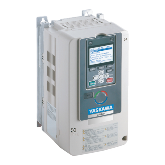
Page 64: Keypad Components And Functions
Install the insulation barriers included in the package between the main circuit terminals. Figure 7.32 Install the Insulation Barriers Put the terminal cover back in its initial position. Keypad Components and Functions Figure 8.1 Keypad YASKAWA TOEPC71061737D GA800 DRIVE INSTALLATION & PRIMARY OPERATION... - Page 65 LOCAL Mode. USB Terminal For factory adjustment Connects to the drive using an RJ-45 8-pin straight through UTP CAT5e extension cable or keypad connector. RJ-45 Connector YASKAWA TOEPC71061737D GA800 DRIVE INSTALLATION & PRIMARY OPERATION...
- Page 66 Accept Existing RUN Command], the drive can start suddenly. Before you change the control source, remove all personnel from the area around the drive, motor, and load. Sudden starts can cause serious injury or death. YASKAWA TOEPC71061737D GA800 DRIVE INSTALLATION & PRIMARY OPERATION...
-
Page 67: Keypad Mode And Menu Displays
8 Keypad Components and Functions ◆ Keypad Mode and Menu Displays Figure 8.2 Keypad Functions and Display Levels YASKAWA TOEPC71061737D GA800 DRIVE INSTALLATION & PRIMARY OPERATION... -
Page 68: Led Status Ring
Sets data logs and backlight. Diagnostic Tools LED Status Ring The LED Status Ring on the drive cover shows the drive operating status. A - ALM/ERR C - RUN B - Ready YASKAWA TOEPC71061737D GA800 DRIVE INSTALLATION & PRIMARY OPERATION... -
Page 69: Drive Start-Up
Figure 9.1 LED Flashing Statuses Figure 9.2 Relation between RUN LED and Drive Operation Drive Start-Up 1. Install and wire the drive. 2. Energize the drive. 3. Run the Setup Wizard to automatically set these functions: YASKAWA TOEPC71061737D GA800 DRIVE INSTALLATION & PRIMARY OPERATION... -
Page 70: Setup Wizard
• Nominal voltage: 3 V • Operating temperature range: -20°C to +85°C (-4°F to +185°F) • Nominal battery life: 2 years (20°C (68°F) ambient temperature) YASKAWA TOEPC71061737D GA800 DRIVE INSTALLATION & PRIMARY OPERATION... -
Page 71: Change Parameter Setting Values
• If [Home] is not shown above the , push (Back). Push (Menu). Push to select [Parameters], then push Push to select [C Tuning], then push Push to select [C1 Accel & Decel Time], then push YASKAWA TOEPC71061737D GA800 DRIVE INSTALLATION & PRIMARY OPERATION... -
Page 72: Disable The Initial Setup Screen
• When the drive is in HOME Mode, the screen shows [Home] in the upper right-hand corner of the screen. • If the screen does not show [Home] for , push (Back), and then push to show [Home]. Push (Menu). Push to select [Initial Setup], then push YASKAWA TOEPC71061737D GA800 DRIVE INSTALLATION & PRIMARY OPERATION... -
Page 73: Control Circuit Terminal Block Functions
Damage to Equipment. Do not energize and de-energize the drive more frequently than one time each 30 minutes. If you frequently energize and de-energize the drive, it can cause drive failure. ■ Input Terminals Refer to Table 10.1 for a list of input terminals and functions. YASKAWA TOEPC71061737D GA800 DRIVE INSTALLATION & PRIMARY OPERATION... - Page 74 • PTC input (Motor Overheat Protection) Set DIP switch S4 to “PTC” and set DIP switch S1-3 to “V” to set terminal A3 for PTC input. Frequency reference common E (G) Connecting shielded cable YASKAWA TOEPC71061737D GA800 DRIVE INSTALLATION & PRIMARY OPERATION...
-
Page 75: Output Terminals
(Zero Speed) Note: Do not set functions that frequently switch ON/OFF to MFDO (M1 to M6) because this will decrease the performance life of the relay contacts. Yaskawa estimates switching life at MFDO 200,000 times (assumes 1 A, resistive load). -
Page 76: Control Circuit Wire Gauges And Tightening Torques
Use the tables in this section to select the correct wires. Use shielded wire to wire the control circuit terminal block. Use crimp ferrules on the wire ends to make the wiring procedure easier and more reliable. YASKAWA TOEPC71061737D GA800 DRIVE INSTALLATION & PRIMARY OPERATION... -
Page 77: Wiring The Control Circuit Terminal
• Connect the shield of shielded cable to the applicable ground terminal. Incorrect equipment grounding can cause drive or equipment malfunction from electrical interference. Correctly ground the drive terminals and complete main circuit wiring before you wire the control circuit. Remove the keypad and front cover. YASKAWA TOEPC71061737D GA800 DRIVE INSTALLATION & PRIMARY OPERATION... - Page 78 B - LED status ring board Figure 10.6 Remove the LED Status Ring Board A - Drive front C - Temporary placement holes B - LED status ring board Figure 10.7 Remove the LED Status Ring Board YASKAWA TOEPC71061737D GA800 DRIVE INSTALLATION & PRIMARY OPERATION...
- Page 79 A - Connect the shield to terminal E C - Insulate with electrical tape or (G) of the drive. shrink tubing. B - Sheath Figure 10.9 Prepare the Ends of Shielded Wire YASKAWA TOEPC71061737D GA800 DRIVE INSTALLATION & PRIMARY OPERATION...
-
Page 80: Switches And Jumpers On The Terminal Board
Switches and Jumpers on the Terminal Board The terminal board has switches to adapt the drive I/Os to the external control signals as shown in Figure 10.13. Set the switches to select the functions for each terminal. YASKAWA TOEPC71061737D GA800 DRIVE INSTALLATION & PRIMARY OPERATION... -
Page 81: Control I/O Connections
8 V or more 10 kΩ or more 10 V or more Note: Use the formula in Figure 10.14 to calculate the necessary load resistance (kΩ) to increase output voltage V (V). YASKAWA TOEPC71061737D GA800 DRIVE INSTALLATION & PRIMARY OPERATION... -
Page 82: Set Sinking Mode/Sourcing Mode
Damage to Equipment. Do not close the circuit between terminals SP-SN. If you close the circuits between terminals SC-SP and terminals SC-SN at the same time, it will cause damage to the drive. YASKAWA TOEPC71061737D GA800 DRIVE INSTALLATION & PRIMARY OPERATION... -
Page 83: Set Input Signals For Mfai Terminals A1 To A3
1: -10 V to +10 V/-100% to 100% (input impedance: 20 kΩ) S1-3 H3-05 2: 4 mA to 20 mA/0% to 100% (input impedance: 250 Ω) Current input 3: 0 mA to 20 mA/0% to 100% (input impedance: 250 Ω) YASKAWA TOEPC71061737D GA800 DRIVE INSTALLATION & PRIMARY OPERATION... -
Page 84: Set Mfai Terminal A3 To Ptc Input
Set the signal type for terminals AM and FM to voltage or current output. Use jumper switch S5 and H4-07, H4-08 [Terminal FM Signal Level Select, Terminal AM Signal Level Select] to set the signal type. Figure 10.18 Location of Jumper Switch S5 YASKAWA TOEPC71061737D GA800 DRIVE INSTALLATION & PRIMARY OPERATION... -
Page 85: Switch On Termination Resistor For Memobus/Modbus Communications
Refer to the Technical Reference for information about speed feedback and Permanent Magnet/Synchronous Reluctance motor control methods. Set the most applicable control method for your application. Parameter A1-02 [Control Method Selection] sets drive control. YASKAWA TOEPC71061737D GA800 DRIVE INSTALLATION & PRIMARY OPERATION... -
Page 86: Drive Duty Modes
• The motor test report data is not available. Select this tuning mode when: • The drive and motor capacities are different. Line-to-Line Resistance • The drive is in V/f Control. • You replaced the drive and the motor. YASKAWA TOEPC71061737D GA800 DRIVE INSTALLATION & PRIMARY OPERATION... -
Page 87: Drive Parameters
CL-V/f AOLV OLV/PM OLV/PM AOLV/PM CLV/PM EZOLV A1-03 Initialize Parameters (0103) Sets parameters to default values. 0 : No Initialization 1110 : User Initialization 2220 : 2-Wire Initialization 3330 : 3-Wire Initialization YASKAWA TOEPC71061737D GA800 DRIVE INSTALLATION & PRIMARY OPERATION... - Page 88 F : User Defined (C6-03 to C6-05) CL-V/f AOLV OLV/PM OLV/PM AOLV/PM CLV/PM EZOLV d1-01 - d1-16 Reference 1 to 16 (0280 - 0291) Sets the frequency reference in the units from o1-03 [Frequency Display Unit Selection. YASKAWA TOEPC71061737D GA800 DRIVE INSTALLATION & PRIMARY OPERATION...
- Page 89 Sets the function for MFAI terminal A3. CL-V/f AOLV OLV/PM OLV/PM AOLV/PM CLV/PM EZOLV H3-07 Terminal A3 Gain Setting (0415) Sets the gain of the analog signal input to MFAI terminal A3. YASKAWA TOEPC71061737D GA800 DRIVE INSTALLATION & PRIMARY OPERATION...
- Page 90 Terminal AM Signal Level Select (0424) Sets the MFAO terminal AM output signal level. 0 : 0 to 10 Vdc 1 : -10 to +10 Vdc 2 : 4 to 20 mA YASKAWA TOEPC71061737D GA800 DRIVE INSTALLATION & PRIMARY OPERATION...
-
Page 91: Ul Standards
• IP55/UL Type 12 Heatsink External Mounting; front side: -10 °C to +50 °C (14 °F to 122 °F) • IP55/UL Type 12 Heatsink External Mounting; back side: -10 °C to +40 °C (14 °F to 104 °F) YASKAWA TOEPC71061737D GA800 DRIVE INSTALLATION & PRIMARY OPERATION... -
Page 92: Wire The Main Circuit Terminal Block
To comply with UL standards on drive models 2257 to 2415, 4208 to 4H12, and T208 to T720, use UL Listed closed- loop crimp terminals and heat-shrinkable tubing. Use the tools recommend by the terminal manufacturer to crimp the closed-loop crimp terminal. Yaskawa recommends closed-loop crimp terminals and heat-shrinkable tubing from PANDUIT Corp. - Page 93 1/0 × 2P 1/0 × 2P S1/0-38R-X 3/0 × 2P S3/0-38R-5 4208 P4-38R-E S4-38R-E 2/0 × 2P 2/0 × 2P S2/0-38R-X 3/0 × 2P S3/0-38R-5 4250 1/0 × 2P S1/0-38R-X P2-38R-X S2-38R-X YASKAWA TOEPC71061737D GA800 DRIVE INSTALLATION & PRIMARY OPERATION...
- Page 94 1/0 × 4P × 2 LCA1/0-12-X LCA3/0-12-X 4/0 × 4P × 2 4/0 × 4P × 2 LCA4/0-12-X 4/0 × 4P × 2 LCA4/0-12-X 4930 1/0 × 4P × 2 LCA1/0-12-X LCA3/0-12-X YASKAWA TOEPC71061737D GA800 DRIVE INSTALLATION & PRIMARY OPERATION...
- Page 95 When you use drive models 4810 to 4H12 as a 6-Phase/12-Pulse drive, remove the common bus bars on the input terminals. For use with PANDUIT Corp. heat-shrinkable tubing HSTT-series or an equivalent UL-recognized heat-shrinkable tubing rated 600 V minimum. YASKAWA TOEPC71061737D GA800 DRIVE INSTALLATION & PRIMARY OPERATION...
- Page 96 LCA300-12-X 300 × 4P LCAX300-12-6 T720 4/0 × 4P 4/0 × 4P S4/0-12R-5 S2/0-12R-X For use with PANDUIT Corp. heat-shrinkable tubing HSTT-series or an equivalent UL-recognized heat-shrinkable tubing rated 600 V minimum. YASKAWA TOEPC71061737D GA800 DRIVE INSTALLATION & PRIMARY OPERATION...
-
Page 97: Ul Compliance
– When you use semiconductor fuses as UL listed drive protection, the drives and fuses must be in the same enclosure. – Where multiple semiconductor fuse ratings are listed for a single drive, Yaskawa recommends a fuse with a large rated current for applications with repeated loads of approximately 150%. You can use smaller semiconductor fuses of the same manufacturer and series than what is listed. -
Page 98: Three-Phase 400 V Class
Amps Fuses in Same Same or Same or in UL Type 1 Enclosure Separate Separate Kit) Only) Enclosure) Enclosure) FWH-40B, FWH- 4002 4195 4004 FWH-50B 4195 4005 FWH-50B 4195 4007 FWH-60B 4195 YASKAWA TOEPC71061737D GA800 DRIVE INSTALLATION & PRIMARY OPERATION... - Page 99 You cannot use Class CC, J, or T Fuses. Install the fuses into an enclosure with the necessary minimum enclosure volume. Enclosure volume is not restricted. Refer to the values in “Any Size Protected Enclosure (Ventilated/Non-Ventilated)” column for details on the fuses. YASKAWA TOEPC71061737D GA800 DRIVE INSTALLATION & PRIMARY OPERATION...
-
Page 100: 6-Phase/12-Pulse 400 V Class
2042 FWH-150B 2008 FWH-45B 2056 FWH-200B 2010 FWH-45B 2070 FWH-225A FWH-50B 2082 FWH-250A 2012 FWH-80B 2110 FWH-250A FWH-100B 2138 FWH-300A FWH-80B 2018 FWH-100B 2169 FWH-350A FWH-80B 2211 FWH-450A 2021 FWH-100B 2257 FWH-600A YASKAWA TOEPC71061737D GA800 DRIVE INSTALLATION & PRIMARY OPERATION... -
Page 101: Low Voltage Wiring For Control Circuit Terminals
You must provide low voltage wiring as specified by the National Electric Code (NEC), the Canadian Electric Code, Part I (CEC), and local codes. Yaskawa recommends the NEC class 1 circuit conductor. Use the UL approved class 2 power supply for external power supply. -
Page 102: Drive Motor Overload And Overheat Protection
AOLV OLV/PM OLV/PM AOLV/PM CLV/PM EZOLV E9-06 Motor Rated Current (FLA) Determined by E9-01 and o2-04 (11E9) Sets the motor rated current in amps. (10% to 200% of the drive rated current) YASKAWA TOEPC71061737D GA800 DRIVE INSTALLATION & PRIMARY OPERATION... -
Page 103: L1-01: Motor Overload (Ol1) Protection
The overload tolerance characteristics of the motor change the trigger point for the electronic thermal protection. This provides motor overheat protection from low speed to high speed across the full speed range. YASKAWA TOEPC71061737D GA800 DRIVE INSTALLATION & PRIMARY OPERATION... - Page 104 (1% frequency. Operating slower than 1% speed at 100% load base frequency). will cause motor overload. 4 : PM Variable Torque Use this setting for PM motors with derated torque characteristics. YASKAWA TOEPC71061737D GA800 DRIVE INSTALLATION & PRIMARY OPERATION...
- Page 105 Operate at a 50 Hz base frequency to maximize the line power, the drive will detect oL1. The drive triggers a motor cooling ability. fault relay output and the motor coasts to stop. YASKAWA TOEPC71061737D GA800 DRIVE INSTALLATION & PRIMARY OPERATION...
-
Page 106: L1-02: Motor Overload Protection Time
2 : Fast Stop (Use C1-09) The drive stops the motor in the deceleration time set in C1-09 [Fast Stop Time]. Fault relay output terminal MA-MC turns ON, and MB-MC turns OFF. 3 : Alarm Only YASKAWA TOEPC71061737D GA800 DRIVE INSTALLATION & PRIMARY OPERATION... -
Page 107: L1-04: Motor Thermistor Oh Fault Select
EU ErP Directive The drive meets the requirements for IE2 efficiency according to the European regulation 2019/1781. 2009/125/EC The losses and the efficiency were measured in accordance with the requirements of IEC 61800-9-2. YASKAWA TOEPC71061737D GA800 DRIVE INSTALLATION & PRIMARY OPERATION... -
Page 108: Eu Declaration Of Conformity
4xxxxA, TxxxxA), use an enclosure panel that does not let unwanted material enter the drive from above or below. ■ Electrical Installation Refer to Figure 13.2 Figure 13.3 for examples of drives that are wired to comply with the CE Low Voltage Directive. YASKAWA TOEPC71061737D GA800 DRIVE INSTALLATION & PRIMARY OPERATION... - Page 109 13 European Standards Three-Phase Drive Figure 13.2 Wiring Diagram for CE Low Voltage Directive Compliance YASKAWA TOEPC71061737D GA800 DRIVE INSTALLATION & PRIMARY OPERATION...
- Page 110 Reinforced insulation separates the output terminals from other circuits. You can also connect circuits that are not Safety Extra-Low Voltage circuits when the drive output is 250 Vac, 1 A maximum or 30 VDC, 1 A maximum. YASKAWA TOEPC71061737D GA800 DRIVE INSTALLATION & PRIMARY OPERATION...
- Page 111 13 European Standards 6-Phase/12-Pulse Drives Figure 13.3 Wiring Diagram for CE Low Voltage Directive Compliance: 6-Phase/12-Pulse Drives YASKAWA TOEPC71061737D GA800 DRIVE INSTALLATION & PRIMARY OPERATION...
-
Page 112: Main Circuit Wire Gauges And Tightening Torques
• Refer to the instruction manual for each device for recommended wire gauges to connect peripheral devices or options to terminals +1, +2, +3, -, B1, and B2. Contact Yaskawa or your nearest sales representative if the recommended wire gauges for the peripheral devices or options are out of the range of the applicable gauges for the drive. - Page 113 -, +1, +2 (2.5 - 16) (19.8 - 22) 2.5 - 4 1.5 - 1.7 B1, B2 (2.5 - 4) (13.5 - 15) 6 - 10 2.0 - 2.5 (17.7 - 22.1) YASKAWA TOEPC71061737D GA800 DRIVE INSTALLATION & PRIMARY OPERATION...
- Page 114 2110 -, +1 (25 - 50) (89 - 107) 6 - 25 3 - 3.5 B1, B2 (6 - 25) (27 - 31) 16 - 25 5.4 - 6.0 (47.8 - 53.1) YASKAWA TOEPC71061737D GA800 DRIVE INSTALLATION & PRIMARY OPERATION...
- Page 115 35 - 120 × 2P 2313 -, +1 95 × 2P (120 × 2P) (177) 25 - 70 × 2P 50 × 2P (70 × 2P) (177) 95 - 240 18 - 23 (159 - 204) YASKAWA TOEPC71061737D GA800 DRIVE INSTALLATION & PRIMARY OPERATION...
- Page 116 -, +1, +2 (2.5 - 16) (19.8 - 22) 2.5 - 4 1.5 - 1.7 B1, B2 (2.5 - 4) (13.5 - 15) 2.5 - 10 1.2 - 1.5 (10.6 - 13.3) YASKAWA TOEPC71061737D GA800 DRIVE INSTALLATION & PRIMARY OPERATION...
- Page 117 -, +1, +2 (2.5 - 16) (19.8 - 22) 2.5 - 4 1.5 - 1.7 B1, B2 (2.5 - 4) (13.5 - 15) 2.5 - 10 2.0 - 2.5 (17.7 - 22.1) YASKAWA TOEPC71061737D GA800 DRIVE INSTALLATION & PRIMARY OPERATION...
- Page 118 4060 -, +1 (6 - 25) (19.8 - 22) 2.5 - 10 1.5 - 1.7 B1, B2 (2.5 - 10) (13.5 - 15) 10 - 25 5.4 - 6.0 (47.8 - 53.1) YASKAWA TOEPC71061737D GA800 DRIVE INSTALLATION & PRIMARY OPERATION...
- Page 119 4168 -, -, +1, +1 (50) (71 - 80) 25 - 70 8 - 9 B1, B2 (50 - 70) (71 - 80) 25 - 50 9.0 - 11 (79.7 - 97.4) YASKAWA TOEPC71061737D GA800 DRIVE INSTALLATION & PRIMARY OPERATION...
- Page 120 95 - 185 × 2P 4414 -, +1 120 × 2P (185 × 2P) (310) 50 - 95 × 2P 95 × 2P (310) 35 - 240 32 - 40 (283 - 354) YASKAWA TOEPC71061737D GA800 DRIVE INSTALLATION & PRIMARY OPERATION...
- Page 121 95 - 150 × 4P 4810 -, +1 150 × 4P (310) 70 - 150 × 4P 70 × 4P (310) 70 - 120 32 - 40 120 × 2P (283 - 354) YASKAWA TOEPC71061737D GA800 DRIVE INSTALLATION & PRIMARY OPERATION...
- Page 122 A junction terminal is necessary to connect a braking resistor unit (LKEB-series) to terminals B1 and B2. When you connect a braking unit (CDBR-type) to terminals - and +3, refer to Braking Unit Connection Wire Gauge (CDBR-Type) on page YASKAWA TOEPC71061737D GA800 DRIVE INSTALLATION & PRIMARY OPERATION...
- Page 123 (20 - 27) 15.3 U/T1, V/T2, W/T3 25 - 70 (135) T103 3.1 - 3.8 -, +3 1.5 - 50 (28 - 33) 5.4 - 6 16 - 25 (47.8 - 53.1) YASKAWA TOEPC71061737D GA800 DRIVE INSTALLATION & PRIMARY OPERATION...
- Page 124 R1/L11, S1/L21, T1/L31 (310) U/T1, V/T2, W/T3 120 × 2 70 - 150 (310) T371 -, +3 70 × 2 35 - 150 (310) 32 - 40 120 - 240 (283 - 354) YASKAWA TOEPC71061737D GA800 DRIVE INSTALLATION & PRIMARY OPERATION...
-
Page 125: Connect A Fuse To The Input Side (Primary Side)
Connect a Fuse to the Input Side (Primary Side) The drive circuit protection must comply with IEC/EN 61800-5-1 for protection against a short circuit in the internal circuitry. Yaskawa recommends that you install semiconductor protection fuses or ELCBs on the input side for branch circuit protection. - Page 126 Then check the wiring and peripheral device ratings to find the cause of the problem. If you do not know the cause of the problem, contact Yaskawa before you energize the drive or peripheral devices. If you do not fix the problem before you operate the drive or peripheral devices, it can cause serious injury or death.
-
Page 127: Ce Standards Compliance For Dc Power Supply Input
• On models 4810 to 4H12, use DC power supply input terminals +1 and - to connect a converter that can do protection coordination on the input side, for example a Yaskawa D1000-series Power Regenerative Converter. You cannot use a DC power supply to connect drives in parallel. -
Page 128: China Rohs Compliance
FWH-1000B FWH-450A 2360 FWH-1000B 2211 FWH-600A 2415 FWH-1000B Yaskawa recommends a fuse with a large rated current for applications with repeated loads. Table 13.7 Recommended Fuse (Three-Phase 400 V Class) Fuse Fuse Manufacturer: Bussmann Manufacturer: Bussmann Drive Model Drive Model... -
Page 129: Information On Hazardous Substances In This Product
汞 镉 六价铬 多溴联苯 多溴二苯醚 (Pb) (Hg) (Cd) (Cr(VI)) (PBB) (PBDE) 实装基板 ○ ○ ○ ○ ○ × 电子元件 ○ ○ ○ ○ ○ × 黄铜螺钉 ○ ○ ○ ○ ○ × YASKAWA TOEPC71061737D GA800 DRIVE INSTALLATION & PRIMARY OPERATION... -
Page 130: Safe Disable Input
○:表示该有害物质在该部件所有均质材料中的含量均在GB/T 26572规定的限量要求以下。 ×:表示该有害物质至少在该部件的某一均质材料中的含量超出GB/T 26572规定的限量要求。 (注) 本产品符合欧盟RoHS指令。上表中的“×”表示含有欧盟RoHS指令豁免的有害物质。 Safe Disable Input This section gives precautions to support the Safe Disable input. Contact Yaskawa for more information. The safety function complies with the standards shown in Table 16.1. Table 16.1 Applied Safety Standards and Unified Standards... -
Page 131: Notes
Set the EDM function to one of the MFDO terminals [H2-xx = 21 or 121] to monitor the status of the Safe Disable function. This is the “Safe Disable monitor output function”. YASKAWA TOEPC71061737D GA800 DRIVE INSTALLATION & PRIMARY OPERATION... -
Page 132: Enabling And Disabling The Drive Output ("Safe Torque Off")
H1 and H2 to hold for at least 3 ms. The drive may not be able to switch to the “Safe Torque Off” status if terminals H1 and H2 are only open for less than 3 ms. YASKAWA TOEPC71061737D GA800 DRIVE INSTALLATION & PRIMARY OPERATION... -
Page 133: Safe Disable Monitor Output Function And Keypad Display
2. Monitor the ON/OFF status of the input channels and make sure that MFDO set to the EDM function operates as shown in Table 16.3. If one or more of these items are true, the ON/OFF status of the MFDO may not display correctly on the keypad: YASKAWA TOEPC71061737D GA800 DRIVE INSTALLATION & PRIMARY OPERATION... -
Page 134: Seismic Standards
• Customers are responsible for microSD card data protection. PC functions that format and delete the data may not be sufficient to fully erase the microSD card data. Yaskawa recommends that customers physically destroy the microSD card in a shredder or use data wipe software to fully erase the card. -
Page 135: Weee Directive
– The keypad shows the fault code. – and ALM/ERR on the LED Status Ring illuminate continuously. – The drive shuts off output and the fault relay output activates. The motor coasts to stop. • For drive alarms: YASKAWA TOEPC71061737D GA800 DRIVE INSTALLATION & PRIMARY OPERATION... -
Page 136: Fault
Modbus Communication Error There is a short circuit in the communications cable • Repair short circuits and connect cables. or the communications cable is not connected. • Replace the defective communications cable. YASKAWA TOEPC71061737D GA800 DRIVE INSTALLATION & PRIMARY OPERATION... - Page 137 Control Circuit Error CPF03, CPF07 • If the fault stays, replace the control board or the drive. For to CPF08, information about replacing the control board, contact Yaskawa CPF11 to or your nearest sales representative. CPF14, CPF16 to CPF24, and...
- Page 138 The encoder cable is disconnected or wired If the fault stays, replace the control board or the drive. For incorrectly. information about replacing the control board, contact Yaskawa or your nearest sales representative. Noise interference along the encoder cable. Isolate the encoder cable from the drive output line or a different Z Pulse Noise Fault Detection source of electrical interference.
- Page 139 Error • If the fault stays, replace the control board or the drive. For information about replacing the control board, contact Yaskawa or your nearest sales representative. There is a problem with the EEPROM data. Set A1-03 = 2220, 3330 [Initialize Parameters = 2-Wire Initialization, 3-Wire Initialization] to initialize the drive, then upload the DriveWorksEZ project to the drive again.
- Page 140 A fault occurred in the feedback input circuit of the Replace the control board or the drive. For information about drive. replacing the control board, contact Yaskawa or your nearest sales representative. The FbL detection level is set incorrectly. Adjust b5-13 [PID Feedback Loss Detection Lvl] and b5-14 [PID PID Feedback Loss Feedback Loss Detection Time].
- Page 141 • Decrease the stray capacitance. There was a problem with the drive hardware. Replace the control board or the drive. For information about replacing the control board, contact Yaskawa or your nearest sales representative. Communication data error occurred between the...
- Page 142 U/T1, V/T2, and W/T3. Make sure that there is not a drive. short circuit in terminals - and terminals U/T1, V/T2, and W/T3. • If there is a short circuit, contact Yaskawa or your nearest sales representative. • Calculate the torque necessary during acceleration related to the The acceleration time is too short.
- Page 143 If the problem continues, replace the option card. oFC50 to Option Card Error Occurred at A fault occurred in the option card. Refer to the manual for the PG-RT3 or PG-F3 option card. oFC55 Option Port CN5-C YASKAWA TOEPC71061737D GA800 DRIVE INSTALLATION & PRIMARY OPERATION...
- Page 144 For general-purpose motors, overload can occur while running at low speed when operating at below the rated current. L1-01 [Motor Overload (oL1) Protection] is set Set L1-01 in as specified by the motor qualities for a drive-dedicated incorrectly. motor. YASKAWA TOEPC71061737D GA800 DRIVE INSTALLATION & PRIMARY OPERATION...
- Page 145 • Decrease the value set in n3-21 [HSB Current Suppression Level]. Overtorque Detection 1 A fault occurred on the machine. Examine the machine and remove the cause of the fault. Example: The machine is locked. YASKAWA TOEPC71061737D GA800 DRIVE INSTALLATION & PRIMARY OPERATION...
- Page 146 Examine the motor main circuit cable, terminals, and motor (the current short to ground is charging the main terminal box, and then remove ground faults. circuit capacitor of the drive through the power Re-energize the drive. supply). YASKAWA TOEPC71061737D GA800 DRIVE INSTALLATION & PRIMARY OPERATION...
- Page 147 [CapacitorMaintenance]. If U4-05 is more than 90%, replace the control board or the drive. For information about replacing the control board, contact Yaskawa or your nearest sales representative. • If drive input power is correct and the fault stays, replace the control board or the drive.
- Page 148 U/T1, V/T2, and W/T3. Make sure that there is not a drive. short circuit in terminals - and terminals U/T1, V/T2, and W/T3. • If there is a short circuit, contact Yaskawa or your nearest sales representative. When A1-02 = 5, 6, 7 [Control Method Selection = Set L8-27 correctly.
-
Page 149: Minor Faults/Alarms
[CapacitorMaintenance]. If U4-05 is more than 90%, replace the control board or the drive. For information about replacing the control board, contact Yaskawa or your nearest sales representative. The relay or contactor on the soft-charge bypass relay U4-06 [PreChargeRelayMainte] shows the performance life of the is damaged. - Page 150 There is damage to the communications circuitry. • Do a self-diagnostics check. • If the problem continues, replace the control board or the drive. Contact Yaskawa or your nearest sales representative to replace the control board. The termination resistor setting for MEMOBUS/ On the last drive in a MEMOBUS/Modbus network, set DIP switch Modbus communications is incorrect.
- Page 151 Correctly connect the signal line to MFDI terminal S2. External Fault [H1-02 = 2C to 2F] is set to MFDI Correctly set the MFDI. terminal S2, but the terminal is not in use. YASKAWA TOEPC71061737D GA800 DRIVE INSTALLATION & PRIMARY OPERATION...
- Page 152 A fault occurred in the feedback input circuit of the Replace the control board or the drive. For information about drive. replacing the control board, contact Yaskawa or your nearest sales representative. The FbL detection level is set incorrectly. Adjust b5-13 [PID Feedback Loss Detection Lvl] and b5-14 [PID PID Feedback Loss Feedback Loss Detection Time].
- Page 153 The capacitors for the main circuit and control circuit Replace the control board or the drive. For information about are at 90% of expected performance life. replacing the control board, contact Yaskawa or your nearest sales representative. The soft charge bypass relay is at 90% of its expected Replace the control board or the drive.
- Page 154 Note: • You can change 150 parameters maximum. • If you change parameters that have dependencies, the drive can detect ovEr when the number of changed parameters is fewer than 150. YASKAWA TOEPC71061737D GA800 DRIVE INSTALLATION & PRIMARY OPERATION...
- Page 155 • When the Safe Disable function is not in use, use a jumper to connect terminals H1-HC and H2-HC. There is internal damage to the two Safe Disable Replace the board or the drive. Contact Yaskawa or your nearest channels. sales representative to replace the board.
-
Page 156: Parameter Setting Errors
Air inside the drive is too hot. Check the ambient temperature of the drive. The Charge LED is broken. Replace the control board or the entire drive. For information about replacing the control board, contact Yaskawa or your nearest sales representative. ◆ Parameter Setting Errors Parameter setting errors occur when multiple parameter settings do not agree, or when parameter setting values are not correct. - Page 157 These parameters are set at the same time: Remove one of the function settings. • H1-xx = 62 [Speed Search from Fref] • H5-22 = 1 [Speed Search from MODBUS = Enabled] YASKAWA TOEPC71061737D GA800 DRIVE INSTALLATION & PRIMARY OPERATION...
- Page 158 Selection]. parameters that are not in the applicable setting range. Correct the parameter settings. Note: If more than one error occurs at the same time, other oPExx errors have priority over oPE02. YASKAWA TOEPC71061737D GA800 DRIVE INSTALLATION & PRIMARY OPERATION...
- Page 159 • For motor 2: E3-09 ≤ E3-07 < E3-06 ≤ E3-11 ≤ E3-04 [Minimum Output Frequency ≤ Mid Point A Frequency < Base Frequency ≤ Mid Point B Frequency ≤ Maximum Output Frequency] YASKAWA TOEPC71061737D GA800 DRIVE INSTALLATION & PRIMARY OPERATION...
- Page 160 Decrease the value set for E1-04 [Maximum Output Frequency] and maximum speed is more than 20 kHz. make sure that the output frequency of the encoder is not more than 20 kHz. YASKAWA TOEPC71061737D GA800 DRIVE INSTALLATION & PRIMARY OPERATION...
-
Page 161: Auto-Tuning Errors
Auto-Tuning again. A1-02 [Control Method Selection] setting is not • Examine the value set in A1-02. applicable. • Make sure that the input motor nameplate data is correct, and do Auto-Tuning again. YASKAWA TOEPC71061737D GA800 DRIVE INSTALLATION & PRIMARY OPERATION... - Page 162 • Make sure that the input motor nameplate data is correct. The motor nameplate data entered during Auto- Tuning is incorrect. • Do Auto-Tuning again and correctly set the motor nameplate data. YASKAWA TOEPC71061737D GA800 DRIVE INSTALLATION & PRIMARY OPERATION...
- Page 163 There was a current detection signal error. Replace the control board or the drive. For information about replacing the control board, contact Yaskawa or your nearest sales representative. The motor rated current value is incorrect. Correctly set the rated current indicated on the motor nameplate and...
-
Page 164: Backup Function Operating Mode Display And Errors
Note: If the drive detects Er-25 after doing Stationary Auto-Tuning, the motor may not be able to use high frequency injection control. Contact Yaskawa or your nearest sales representative for more information. ◆ Backup Function Operating Mode Display and Errors ■... - Page 165 The parameters are not stored in the keypad. Connect a keypad that has the correct parameters. Restore the parameters. The password set in the backup operation with qx-xx Set the DWEZ PC software password supplied by Yaskawa for the PWEr DWEZ Password Mismatch [DriveWorksEZ Parameters] and rx-xx DWEZ program user ID downloaded to the drive.
-
Page 166: Revision History
Revision: Reviewed and corrected entire documentation May 2019 Addition: Protection design added along with corresponding data. 4, 5, 6, 12 • IP55/UL Type 12 Heatsink External Mounting August 2018 – – First Edition YASKAWA TOEPC71061737D GA800 DRIVE INSTALLATION & PRIMARY OPERATION... - Page 167 YASKAWA TOEPC71061737D GA800 DRIVE INSTALLATION & PRIMARY OPERATION...
- Page 168 Regulations. Therefore, be sure to follow all procedures and submit all relevant documentation according to any and all rules, regulations and laws that may apply. Specifications are subject to change without notice for ongoing product modifications and improvements. Original instructions. © 2018 YASKAWA Electric Corporation TOEPC71061737 Revision: D <3>-0 December 2023...
Need help?
Do you have a question about the GA80U Series and is the answer not in the manual?
Questions and answers