
Subscribe to Our Youtube Channel
Related Manuals for Zeiss MMZ M


Summary of Contents for Zeiss MMZ M
- Page 1 MMZ M Coordinate measuring machine Operating Instructions (Translation of the original operating instructions)
- Page 2 Violations shall result in claims for damages. © ZEISS. All rights reserved. This manual is subject to change, and the ZEISS product described as well as the components therein are subject to technical modifications. All product names are registered trademarks or trademarks of the re- spective owners.
-
Page 3: Table Of Contents
Probing system ...................... 2-3 Changer rack ...................... 2-4 Rotary table ...................... 2-4 Safe operation of the CMM ............ 2-6 Operator requirements................... 2-6 Defining a competent specialist................ 2-6 Requirements for safe use .................. 2-7 Requirements for automatic measuring runs............ 2-8 Basic safety instructions.................. 2-9 61211-1270302 MMZ M Table of contents... - Page 4 Service unit and oil pump.................. 3-7 MSR changer rack .................... 3-8 Control and operation .............. 3-10 Control cabinet .................... 3-10 Control elements on the controller cabinet............ 3-11 Operation ...................... 3-14 Probing system................ 3-18 Types of probing systems .................. 3-18 Contact probing systems.................. 3-18 Optical probing systems .................. 3-20 61211-1270302 MMZ M Table of contents...
- Page 5 Connecting the power supply ................ 6-2 Connecting the compressed air supply .............. 6-2 Setting up the changer rack ................... 6-3 Visual check and check list .................. 6-3 Starting the CMM................ 6-5 Safety measures and notes.................. 6-5 CMM starting sequence .................. 6-6 61211-1270302 MMZ M Table of contents...
- Page 6 Safety during the measuring operation ......... 7-5 Safety instructions.................... 7-5 Precautions ...................... 7-7 Preparation for measuring operation .......... 7-9 Prerequisites for a precise measuring run.............. 7-9 Homing run ...................... 7-9 Stylus system qualification.................. 7-11 Temperature compensation ................. 7-17 Probing the workpiece .............. 7-20 61211-1270302 MMZ M Table of contents...
- Page 7 CMM in end positions.................... 8-7 Service features................ 8-8 Support........................ 8-8 Teleservice ...................... 8-8 Chapter 9 Maintenance and care Maintenance ................. 9-2 Lubrication .................. 9-4 Care.................... 9-5 What you should know! .................. 9-5 Safety instructions.................... 9-6 Measures of precaution .................. 9-6 Overview ....................... 9-7 Care measures ....................... 9-8 Inspection measures..................... 9-11 61211-1270302 MMZ M Table of contents...
- Page 8 Chapter 10 Shutdown and disposal Shutdown.................. 10-2 Disposal.................. 10-3 Package ....................... 10-3 CMM ........................ 10-3 Glossary Alphabetic index 61211-1270302 MMZ M Table of contents...
-
Page 9: Preface
Preface Information about this document The MMZ M coordinate measuring machine (CMM) is described in these operating instructions. These operating instructions apply to all types of the MMZ M series. These operating instructions address operators and users of the coordi- nate measuring machine. -
Page 10: Configuration Of Safety Instructions
A »caution« indicates a personal health hazard. Non-observance of this safety instruction when the described risk oc- curs may cause slight to moderate injuries. Example: Risk of minor crushing of the limbs caused by small loads. 61211-1270302 MMZ M Preface... - Page 11 This symbol refers to possible damage to the CMM. Non-observance of this safety instruction when the event occurs may cause damage to the CMM or one of its components. Example: Collision of the ram with a workpiece. 61211-1270302 MMZ M Preface...
-
Page 12: Markup Elements
Company name CAUTION! The measur- Safety instructions embedded in the text. ing table must be clean. Note: Pay attention to the Note embedded in the text. correct orientation of the qualification marks. Representation of position numbers in texts 61211-1270302 MMZ M Preface... -
Page 13: Chapter 1 Introduction
Introduction Introduction This chapter contains: General specifications .................. 1-2 Warranty ..................... 1-5 61211-1270302 MMZ M... -
Page 14: General Specifications
General specifications General specifications Scope of delivery The standard version of the MMZ M coordinate measuring machine comprises the following components: – Coordinate measuring machine (CMM) – Control unit – Control console (standard version) – Computer with peripheral devices – Software, e.g. CALYPSO –... -
Page 15: Standards And Regulations
General specifications Designation of the ma- Coordinate measuring machine chine: CMM type: MMZ M Additional EU directives: – EMC Directive (2014/30/EU) – RoHS Directive (2011/65/EU) Applied harmonized stan- – EN 60204-1 dards, in particular: – EN 61326-1 Table 2, Class A –... -
Page 16: Separate Document
The following documents are delivered with each CMM: – BP26SE control console – Sensors (information on probing systems) Optional : – LineScan Documentation on data medium The above documents and others are also contained on the supplied data medium. 61211-1270302 MMZ M... -
Page 17: Warranty
– if the necessary maintenance work and measures for care are not carried out according to the technical documentation. Any information regarding maintenance work and measures for care, in- cidentals and wearing parts is specified in separate publications. 61211-1270302 MMZ M... - Page 18 Warranty 61211-1270302 MMZ M...
- Page 19 Safety Safety This chapter contains: Intended use.................... 2-2 Safe operation of the CMM ................ 2-6 Safety on the CMM.................. 2-13 Checking the safety devices ............... 2-22 61211-1270302 MMZ M...
-
Page 20: Intended Use
– Holding and securing a rotary table (optional) – Fastening of the workpieces, installation of changer racks, quali- fication tools and rotary table by use of the threaded holes pro- vided in the measuring plate. – Moving workpieces by means of the rotary table. 61211-1270302 MMZ M... -
Page 21: Probing System
Functions of the contact probe: – Holding the stylus system. – Exact positioning of the stylus system. – Detecting the stylus system deflection and transmitting the signal to the computer. The computer calculates the coordinates of the probed point. 61211-1270302 MMZ M... -
Page 22: Changer Rack
Rotary tables also cal objects facilitate the measurement of prismatic parts. Functions of the rotary table: – Holding the workpiece – Positioning the workpiece – Probing with rotary table – Scanning with rotary table 61211-1270302 MMZ M... - Page 23 Rotary tables must not be used for purposes contrary to the intended use. Examples of reasonably foreseeable misuse: – The rotary table must not be used as storage surface. – The rotary table is not to be sat upon. 61211-1270302 MMZ M...
-
Page 24: Safe Operation Of The Cmm
Work to be carried out by a competent specialist – CMM installation. – Maintenance work on the CMM. – Work on the electrical equipment, for example controller. – Preparation of the measurement: Workpiece setting, creation of measurement plans and automatic measuring runs. 61211-1270302 MMZ M... -
Page 25: Requirements For Safe Use
18 Keep the control console within reach in order to be able to press the EMERGENCY STOP button in cases of emergency. 19 Perform a homing run. 20 Read the notes regarding the end of the measuring operation. 61211-1270302 MMZ M... -
Page 26: Requirements For Automatic Measuring Runs
– It must be ensured that all persons are located outside of the demar- cated area. – If the constant presence of the operator during batch measurement cannot be guaranteed, the relevant safety regulations for unat- tended operation must be observed. 61211-1270302 MMZ M... -
Page 27: Basic Safety Instructions
— Keep a safe distance to moving parts during manual operation. — Ensure that nobody is at risk during manual operation of the ma- chine. — Keep a safe distance away from the CMM during automatic mea- surement runs. 61211-1270302 MMZ M... - Page 28 Falling and concussion injuries on head and body. ü Cables and accessories must not become a tripping or stumbling hazard. — Run the cables through cable ducts. — Install accessories securely at the predefined locations. 2-10 61211-1270302 MMZ M...
-
Page 29: General Precautions
The work area around the CMM must be delimited by means of a light barrier. Do not modify the CMM If the delivered version of the CMM is modified, safe operation of the CMM is no longer guaranteed. 2-11 61211-1270302 MMZ M... - Page 30 – Do not make any alterations to the CMM. Maintenance work Any modification and maintenance work on the CMM may only be car- ried out by ZEISS service engineers or trained personnel authorized by ZEISS. Sufficient illumination Sufficient illumination is required for safe operation of the CMM.
-
Page 31: Safety On The Cmm
– Shearing force limitation (hardware) and drive monitoring (software). – Fall brake of the ram – Collision protection for ram, probe and stylus system – Light barrier NOTE For a safe operation of the CMM, all safety devices must be functional. 2-13 61211-1270302 MMZ M... - Page 32 A separate key is for switching the drives off is provided on the BP26SE control console. If you want to switch the drives off during daily operation, you should use the key shown here. The LED above the key indicates whether the drives are on or off. 2-14 61211-1270302 MMZ M...
- Page 33 2 Emitter at the lower end of the ram 3 Probe When the light beam between emitter and receiver is interrupted by a workpiece or another obstacle, the drives are switched off. All travel movements stop. 2-15 61211-1270302 MMZ M...
- Page 34 NOTE If the fall brake is triggered, i.e. if the Z movement is blocked on the CMM, the fault must be eliminated by specially trained personnel only. 2-16 61211-1270302 MMZ M...
-
Page 35: Light Barrier
Functions of the light barrier The light barrier may have two functions: EMERGENCY STOP and REDUC- TION. The required light barrier function must be set by a ZEISS service engineer during the start-up of the light barrier. It is not possible to switch between the two functions. - Page 36 Also ensure that the con- trol elements cannot be reached from inside the blocked danger zone. Ensure that users can view the entire danger zone from the location of the signal tower for the light barrier. 2-18 61211-1270302 MMZ M...
- Page 37 Distance between compressed air connection and laser beam, minimum 1000 mm Control console Signal tower Distance between signal tower and laser beam, minimum 1000 mm Deflecting mirror Distance between measuring range and laser beam, minimum 900 mm Distance between CMM and laser beam, minimum 400 mm Measuring range 2-19 61211-1270302 MMZ M...
- Page 38 If the LED does not light up, determine the reasons for that. Possible causes: – Incorrect alignment of the emitter, detector or reflecting mirror. – Dirt accumulation on the emitter, detector or reflecting mirror. – Distance between emitter and detector is too large. 2-20 61211-1270302 MMZ M...
- Page 39 Interruption of the beam path If the beam path of the light barrier is interrupted, an EMERGENCY STOP is activated or the travel speed is reduced. The option applied depends ➤ See [ ⇨ 2-17] on the setting. 2-21 61211-1270302 MMZ M...
-
Page 40: Checking The Safety Devices
NOTE When the function of the safety device cannot be guaranteed, the CMM must not be operated. Inform a ZEISS service engineer. Check by the operator Checking the collision protection The CMM is equipped with safety devices for the ram and the probe. - Page 41 The CMM is ready for operation again. You can reactivate the drives. Checking collision protection of the probe It is recommended checking the collision protection function monthly. A check should be carried out when the machine is at rest. 2-23 61211-1270302 MMZ M...
- Page 42 Failure of the protective circuit may cause injuries, such as crushing of parts of the body. The function of the protective circuit must be checked regularly in order to guarantee safe operation of the CMM. — Check the function of the protective circuit every 3 months. 2-24 61211-1270302 MMZ M...
- Page 43 Under normal circumstances, the force of your hand should suffice to stop movement. If the movement cannot be stopped in this way, the protective circuit must be checked immediately by a ZEISS service engi- neer. NOTE If you can stop the travel movements, you will need to reactivate the drives.
-
Page 44: Check By A Specialist
Checking the safety devices Check by a specialist No-contact protective devices Once a year No-contact protective devices such as the light barrier must be checked once a year by a specialist. 2-26 61211-1270302 MMZ M... - Page 45 Description Description This chapter contains: Identification of a CMM ................ 3-2 Design of the CMM .................. 3-3 Components and functions ................ 3-4 Control and operation................ 3-10 Probing system .................. 3-18 61211-1270302 MMZ M...
-
Page 46: Identification Of A Cmm
Z: 1600 mm Type plate The identification of your CMM is given on the type plate. The type plate is located on the drive side of the CMM. Carl Zeiss Industrielle Messtechnik GmbH Carl-Zeiss-Straße 22 73447 Oberkochen Coordinate Measuring Machine XXXXXXXX Ser.Nr.: XXXXX... -
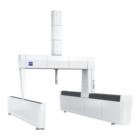
Page 47: Design Of The Cmm
Design of the CMM Design of the CMM A CMM of the MMZ M series is shown below. 1 Ram cover 2 Cover of the X-bridge and the X-carriage 3 Driving column 4 Y guideway for driving column (with bellows cover) -
Page 48: Components And Functions
Components and functions Bridge The MMZ M is a bridge coordinate measuring machine. The bridge is composed of an X-bridge and two columns. The X-carriage in which the ram is guided moves along the X-bridge. The bridge travels in the Y axis. -
Page 49: Coordinate Axes
Moving in three axes is possible with the coordinate measuring machine: X, Y, Z. Travel directions The illustration shows the possible travel directions of the bridge. – – – A Front view B View from the left 61211-1270302 MMZ M... -
Page 50: Reference Standard
It is possible to mount more than one reference sphere onto the reference sphere holder. RSH reference sphere holder 1 Reference sphere 2 Reference sphere shaft 3 Adjustable hemisphere holding the reference sphere shaft 61211-1270302 MMZ M... -
Page 51: Service Unit And Oil Pump
NOTE The filters are equipped with a water separator. If water has accumu- lated in the water separator, it can be drained using the screw on the bottom of the filter. 61211-1270302 MMZ M... -
Page 52: Msr Changer Rack
The oil pump is located on the left side of the controller cabi- net. Impairment of function. Any work on the oil pump may only be carried out by a ZEISS service engineer. MSR changer rack The changer rack comes standard with two tiers: a fixed-height horizon- tal frame profile rail and a height-adjustable profile rail. - Page 53 2 Spacer for mounting profile rail; height-adjustable 3 Profile rail 4 Frame support (leg) 5 Foot profile; consisting of mounting and guide profiles NOTE For more information, please refer to the separate operating instruc- tions for changer racks. 61211-1270302 MMZ M...
-
Page 54: Control And Operation
32-bit control unit. This control unit has the designation C99. NOTE ZEISS USB sticks (backup or boot sticks) may only be used for ZEISS con- trol units and computers by ZEISS service technicians. We do not as- sume any warranty and liability for damage due to other use. -
Page 55: Control Elements On The Controller Cabinet
If the MCC 800 is climate-controlled, the air-conditioning unit is located on the rear side of the control cabinet. Control elements on the controller cabinet Control elements for CMM operation 1 EMERGENCY STOP button; push-and-turn switch 2 Button for clearing the axes 3-11 61211-1270302 MMZ M... - Page 56 – 0: No travel movement possible. – MAN: Manual mode – MAN operat- ing mode. – AUTO: Automatic mode – AUTO op- erating mode. 3-12 61211-1270302 MMZ M...
- Page 57 Activation of the collision protection. The key-operated switch does not remain in this po- sition, but returns to the «active» position. active: Normal operating position. A pilot lamp signals that the collision protection is active. 3-13 61211-1270302 MMZ M...
-
Page 58: Operation
1 Coupling between CMM and loading device is disabled; the CMM can be moved NOTE The switch remains in position «1». After moving the CMM, turn the switch back to «0». Operation BP26SE control console Standard The CMM comes standard with the following control console. 3-14 61211-1270302 MMZ M... - Page 59 The joysticks are required for travel control. This applies to manual and automatic probing. Prior to automatic probing, manual probing is re- quired to program the automatic measurement run. Right joystick The right joystick is used to move the stylus system in the X and Y axes. 3-15 61211-1270302 MMZ M...
- Page 60 Direction Action Movement of the joystick, ram, and rotary table Z direction – Push the joystick to the rear. The ram moves upwards. – Pull the joystick to the front. The ram moves downwards. 3-16 61211-1270302 MMZ M...
- Page 61 The locking must be removed before it will be possible again to carry out travel movements using the joysticks. More information can be found in a separate publication. See operating instructions for the control console. 3-17 61211-1270302 MMZ M...
-
Page 62: Probing System
Probing system Probing system Types of probing systems The MMZ M can be equipped with different probing systems. Probing system VAST XT gold or VAST gold or VAST XTR gold Standard RDS with VAST XXT Option RDS with the optical probe LineScan Option The individual probing systems are explained briefly below. - Page 63 Combination of the RDS articulating system (probe holder) and one probe: RDS articulating system with VAST XXT NOTE The RDS articulating system can be replaced with a VAST probe using an adapter. ZEISS probes with RDS: RDS / … Probe VAST XXT 3-19 61211-1270302...
-
Page 64: Optical Probing Systems
The optical probe can be used in combination with the articulating probe holder. Optical probes in combination with RDS: LineScan Application – Profile measurement You will find further information in the separate operating instructions for optical probing systems. 3-20 61211-1270302 MMZ M... -
Page 65: Chapter 4 Technical Data
Technical data Technical data This chapter contains: CMM...................... 4-2 61211-1270302 MMZ M... -
Page 66: Cmm
Characteristic value Overvoltage category Degree of pollution Protection class Electrical data Electrical data of MCC 800: Line voltage 100/110/115/120/125/230/240 VAC (±10 %) Type of current 1/N/PE Frequency 50 - 60 Hz (±3.5%) Power consumption Maximum 3000 VA Typical 550 W 61211-1270302 MMZ M... -
Page 67: Amount Of Heat Generated
8 Nl/min at 1 bar Travel speed Creep speed: 0 to 5 mm/s Set-up mode: (MAN operating mode) 0 to 90 mm/s Series measurement mode: (AUTO operating mode) Axis max. 300 mm/s Vector (3D) max. 520 mm/s 61211-1270302 MMZ M... -
Page 68: Environmental Conditions
Not OK Wait for 48 hours until the new temperature set is constant. Per hour 20.9-20.0°C 0.9 K 20.0-21.0°C 1.0 K 18.9-20.0°C 1.1 K Not OK Wait for 48 hours until the new temperature set is constant. 61211-1270302 MMZ M... -
Page 69: Chapter 5 Transport And Installation
Transport and installation Transport and installation This chapter contains: Notes...................... 5-2 Transport ..................... 5-3 Installation .................... 5-4 61211-1270302 MMZ M... -
Page 70: Notes
This document in- forms you about all measures to be taken for transport and installation. In the following, we will refer to some of the most important points contained in this document. 61211-1270302 MMZ M... -
Page 71: Transport
»Installation site requirements« document. NOTE The packaging or shipping containers must not be damaged. The pack- aging may only be removed at the installation site by a ZEISS service en- gineer. Ambient temperature The transport pallets or shipping containers must be stored in a covered area until the machine is installed. -
Page 72: Installation
ZEISS for planning purposes. An addi- tional foundation may be necessary. NOTE ZEISS can carry out a vibration analysis for you. Please contact us if you need our support. Installation requirements The following preparations have to be made prior to the installation of... - Page 73 10°C. At least two days in ad- – Store all parts of the CMM in a place having an ambient temperature of at least 10°C for at least two days prior to installation. vance 61211-1270302 MMZ M...
- Page 74 Installation 61211-1270302 MMZ M...
- Page 75 Start-up Start-up This chapter contains: Preparations for start-up ................ 6-2 Starting the CMM .................. 6-5 Mounting / changing the probe .............. 6-8 Preparing the stylus system ................ 6-12 Setting up the workpiece ................ 6-13 Start-up checklist .................. 6-17 61211-1270302 MMZ M...
-
Page 76: Preparations For Start-Up
The visual check should be part of your daily measuring operation rou- tine. Initial start-up by a service engineer Initial start-up is carried out by a ZEISS service engineer. However, you must familiarize yourself with the preparations required for start-up as well as know and follow the corresponding safety instructions. -
Page 77: Setting Up The Changer Rack
Preparations for start-up 2 Call a ZEISS service engineer if you cannot find or eliminate the cause. Setting up the changer rack Instructions for setting up a changer rack are provided in a separate doc- ument. See operating instructions for changer racks. - Page 78 Preparations for start-up – Make sure that it is connected correctly to the supply line and the CMM. Changer rack – Has the changer rack been installed correctly? – Is a stylus system change possible without collision? 61211-1270302 MMZ M...
-
Page 79: Starting The Cmm
– The default speed in the measuring software is reduced. – The light barrier or light curtain has been interrupted. Measuring software NOTE The probe must be connected to the ram before starting the measuring software. 61211-1270302 MMZ M... -
Page 80: Cmm Starting Sequence
This is necessary because the internal computer of the controller re- quires a certain amount of time to start. The starting process must be completed before the drives are switched on. The LEDs on the control console flash during the starting process. 61211-1270302 MMZ M... - Page 81 – Workpiece measurement in a tested measurement run. Switching the computer on 1 Switch on the computer and peripheral devices such as the printer. 2 Boot the computer; start the operating system. 3 Start the measuring software. 61211-1270302 MMZ M...
-
Page 82: Mounting / Changing The Probe
Fastening the RDS The articulating system is slid onto the dovetail guide of the ram and se- cured with a screw. 1 Ram 2 Groove for pin 3 Dovetail guide on the ram 4 Pin 5 RDS articulating system 61211-1270302 MMZ M... - Page 83 Slide the probe onto the dovetail guide of the ram. The probe must al- ways be secured with a screw. 1 Ram 2 Groove for pin 3 Dovetail guide on the ram 4 Pin 5 Probe 6 Cover of the adapter plate receptacle 61211-1270302 MMZ M...
-
Page 84: Replacing A Probe With An Articulating System
RDS/XXT probing system, for example, if the CMM is equipped accordingly. The following description applies to the VAST XT, VAST, and RDS probes. 1 Switch the drives off. 2 Remove the stylus system, store the stylus system in a safe place [1]. 6-10 61211-1270302 MMZ M... - Page 85 Then the styli of the stylus sys- tem must be qualified and the workpiece must be aligned again during the computer-controlled manual run. Please refer to the operating in- structions for the measuring software. 6-11 61211-1270302 MMZ M...
-
Page 86: Preparing The Stylus System
Preparing the stylus system Preparing the stylus system For information on the stylus system, please refer to the separate brochure »Sensors«. Automatic stylus system change ➤ Notes on the automatic change: See [⇨ 7-4]. 6-12 61211-1270302 MMZ M... -
Page 87: Setting Up The Workpiece
— Clean the workpiece and the measuring plate before placing a workpiece on the measuring plate. — Remove any greasy or oily substances from the measuring plate and the workpiece. 6-13 61211-1270302 MMZ M... -
Page 88: Precautionary Measures
2 mm/s. The CMM may be dam- aged if the workpiece is set down hard. 5 Put the workpiece down vertically on the measuring plate. 6 Do not move the workpiece on the measuring plate. 6-14 61211-1270302 MMZ M... -
Page 89: Lowering The Workpiece Onto The Measuring Plate
Position the workpiece so that all required measurements can be carried out without changing the workpiece position. Measuring operation When using a changer rack, position the workpiece so that the measure- ment and the stylus system change can be carried out without collision. without collision 6-15 61211-1270302 MMZ M... -
Page 90: Clamping The Workpiece
— If necessary, use special chucks to avoid deforming of the work- pieces. Clamping equipment Chucks must be screwed onto the measuring plate. Metal, plastic, wood Chucks are generally made of metallic materials. Chucks made of plastic or wood may also be used if necessary. 6-16 61211-1270302 MMZ M... -
Page 91: Start-Up Checklist
– Is the workpiece in the correct position? See [⇨ 6-15] – Is it possible to measure all workpiece dimensions in one cycle? – Is measurement possible without collision? A collision with the changer rack, for example. – Has the workpiece been clamped properly? 6-17 61211-1270302 MMZ M... - Page 92 Start-up checklist 6-18 61211-1270302 MMZ M...
- Page 93 Measuring operation Measuring operation This chapter contains: What you should know!................ 7-2 Safety during the measuring operation............ 7-5 Preparation for measuring operation............ 7-9 Probing the workpiece ................ 7-20 Evaluation of the measuring results ............ 7-23 Terminating the measuring operation............ 7-25 61211-1270302 MMZ M...
-
Page 94: What You Should Know
X, Y and Z. Together these axes form a machine coordinate system. Ad- ditional coordinate systems, e.g. a workpiece coordinate system, are re- quired for exact calculation. More information can be found in a separate brochure. See Operating instructions for the measuring software. 61211-1270302 MMZ M... -
Page 95: Probing And Scanning
The start-up procedure involves a number of worksteps which take a while to perform. Furthermore, the CMM should have been in operation for a prolonged period before performing the first measurement. You can save time by leaving the CMM switched on. 61211-1270302 MMZ M... -
Page 96: Automatic Stylus System Change
You should note which rack holder is allocated to which sty- lus system. NOTE The measuring software is required in order to carry out this procedure. Please refer to the operating instructions for the measuring software. 61211-1270302 MMZ M... -
Page 97: Safety During The Measuring Operation
— Reduce the maximum travel speed either via the control knob on the control console or in the measuring software. — Always keep the control console within reach in order to be able to press the EMERGENCY STOP button in case of emergency. 61211-1270302 MMZ M... - Page 98 Impairment of the function of electronic components due to electromagnetic fields. The functioning of active implants may be impaired. — Keep a minimum distance of 100 mm from the VAST probe or an- other magnetic sources such as magnetic clamping equipment. 61211-1270302 MMZ M...
-
Page 99: Precautions
— Ensure that there is no risk of collision between the styli and parts of the CMM. Faults due to vibrations and shocks NOTE Vibrations and shocks may impair the function of the CMM. Possible causes of vibrations are for example: 61211-1270302 MMZ M... - Page 100 – All existing safety equipment must be used. Make sure that no one is in the danger zone. – For more information on the safety equipment, please refer to the separate “Installation site requirements” brochure. 61211-1270302 MMZ M...
-
Page 101: Preparation For Measuring Operation
The home position corresponds to the origin of the machine coordinate system. It is located in the upper left corner of the measuring volume. The home position must be determined by a homing run prior to the measuring run. 61211-1270302 MMZ M... - Page 102 CMM parts dur- ing the homing run. Additionally, there is a risk of collision in the mea- suring range, for example with the workpiece. — To avoid collisions, move the RDS to the 0°/0° position. 7-10 61211-1270302 MMZ M...
-
Page 103: Stylus System Qualification
– When inserting a new stylus into the stylus system. – When mounting a new probe. What should be observed during qualification? Take the following steps during qualification: 7-11 61211-1270302 MMZ M... - Page 104 VAST XXT TL1 VAST XXT TL3 VAST XXT TL4 Requirements for proper qualification Before starting qualification, make sure that the following prerequisites are met: – The stylus is stable. – All stylus system components are screwed together tightly. 7-12 61211-1270302 MMZ M...
- Page 105 Use the master stylus for this purpose. Proceed as follows: 1 Insert the master stylus. 2 Open the menu for the reference measurement. Please see the user guide for the measuring software. 3 Select stylus 1 on the control console. 7-13 61211-1270302 MMZ M...
- Page 106 Qualification procedure After the reference measurement has been carried out, the stylus sys- tems can be qualified. NOTE During qualification, the temperature effect should be taken into ac- count. — Prior to qualification, carry out temperature compensation. 7-14 61211-1270302 MMZ M...
- Page 107 4 Probe the reference sphere in the shaft direction of the stylus and measure its diameter. The shaft of the reference sphere may not be probed during the qualification. Probing directions during qualification A Correct B Wrong 1 Stylus shaft 2 Probing direction 5 Check the result. 7-15 61211-1270302 MMZ M...
- Page 108 Sources of errors The sources of malfunctions and errors which may lead to increased de- viations are listed below. – Stylus system configuration – Stylus status – Magnetic field – Influence of temperature 7-16 61211-1270302 MMZ M...
-
Page 109: Temperature Compensation
Connecting a temperature sensor to the CMM is possi- ble. 1. Enter the expansion coefficient for the workpiece ma- terial in the measuring software. 2. Connect the temperature sensor. The measuring software calculates the correction value. 7-17 61211-1270302 MMZ M... - Page 110 A temperature sensor is required for the temperature compensation. Two temperature sensors are included in the delivery. The temperature sensor consists of a copper block, a long cable and a connector. 1 Copper block 2 Connector 3 Connection socket on CMM 7-18 61211-1270302 MMZ M...
- Page 111 1 Plug the connector into the connection sockets. The connection sockets are located on the rear side of the CMM. Two sockets are available. 2 Place the copper blocks at two different locations in or on the work- piece to be measured. 7-19 61211-1270302 MMZ M...
-
Page 112: Probing The Workpiece
The travel speed depends on the deflection of the joystick. At the begin- ning and end of the deflection range, the travel speed is proportional to the amount of deflection. The travel speed between the beginning and the end is constant. This speed corresponds to the probing speed. 7-20 61211-1270302 MMZ M... - Page 113 For the various probing systems, certain points must be observed: For more information, please refer to the separate brochure »Sensors«. Preventing measuring errors Measuring errors may have several causes. Answer the following ques- tions before starting the measurement: 7-21 61211-1270302 MMZ M...
- Page 114 Has the reference measurement been carried out? Has the qualification been carried out correctly? When using a measuring probing system, has tensor quali- fication been performed? All styli qualified? Has the correct stylus been selected? Has the temperature compensation been carried out? 7-22 61211-1270302 MMZ M...
-
Page 115: Evaluation Of The Measuring Results
– The structure of the stylus system is not stable. – The stylus system components are not screwed together firmly enough. – Admissible probe limiting values have not been observed. The stylus system is too long, too heavy or contains components which are not suitable. 7-23 61211-1270302 MMZ M... - Page 116 – Different axis clamping set than for qualification. – Different measuring force set than for qualification (depending on the measuring method, with measuring probes) Probing – Probing has not been performed perpendicular to the probing sur- face. 7-24 61211-1270302 MMZ M...
-
Page 117: Terminating The Measuring Operation
The drives are have been switched off if the LED above the key is not lit. 7 Switch off the controller. 8 Switch off the power supply. — Turn the main switch counterclockwise to the «0» position. 7-25 61211-1270302 MMZ M... - Page 118 Terminating the measuring operation 7-26 61211-1270302 MMZ M...
- Page 119 Errors and faults Errors and faults This chapter contains: Errors occurring prior to the measuring operation ........ 8-2 Malfunctions during measuring operations........... 8-3 Special measures.................. 8-5 Service features.................... 8-8 61211-1270302 MMZ M...
-
Page 120: Errors Occurring Prior To The Measuring Operation
1 If the above mentioned errors can be excluded, put the CMM out of operation and repeat the start-up procedure. 2 If measuring operation is still not possible, call a ZEISS service engi- ➤ neer or our support team. -
Page 121: Malfunctions During Measuring Operations
The filter is clogged. – Change the filter. Travel move- The set travel speed is Increase the travel speed: ment too slow. too low. – Turn the control knob on the control console clockwise. 61211-1270302 MMZ M... - Page 122 – Reassign the holder. changer rack or holder has changed. Collision: missing in- – Reassign the holder and set in- termediate positions. termediate positions. Two stylus systems – Reassign the holder. have been assigned to one holder. 61211-1270302 MMZ M...
-
Page 123: Special Measures
If the ram or the probe collides with an obstacle, the guideway and other components of the CMM may become damaged. In this case, per- fect measuring operation is no longer guaranteed. – If measurements are not possible after a collision, call a ZEISS service engineer or our support. Notes... - Page 124 An automatic measuring run may not be carried out after a collision because it could result in another collision. Collision during automatic stylus system change A collision occurring during change may be caused by missing intermedi- ate positions. 61211-1270302 MMZ M...
-
Page 125: Cmm In End Positions
The aim is to move the probe back into the measuring volume. You must not move the CMM away from the measuring vol- ume. 3 Clear the CMM using the joysticks. 4 Reactivate the safety devices. NOTE After clearing, a homing run has to be carried out. 61211-1270302 MMZ M... -
Page 126: Service Features
Within Germany: 0 73 64.20.6337 From abroad: +49.73 64.20.6337 Teleservice ZEISS offers fast and economical help in the form of online diagnostic tools. There are several options here. Teleservice tools – Online diagnosis of errors – Online software update – Online service –... -
Page 127: Chapter 9 Maintenance And Care
Maintenance and care Maintenance and care This chapter contains: Maintenance.................... 9-2 Lubrication.................... 9-4 Care...................... 9-5 61211-1270302 MMZ M... -
Page 128: Maintenance
These persons must have received special training on the corresponding CMM qualifying them to carry out all necessary maintenance work. Maintenance agreement ZEISS offers maintenance agreements relieving you of any need to worry about maintenance. NOTE If you wish to subsequently conclude a maintenance agreement, call our support. - Page 129 Generally, maintenance should be carried out at least every 2000 operating hours. NOTE ZEISS recommends performing little and complete maintenance on an alternating basis: little maintenance in the first year and complete main- tenance in the second year.
-
Page 130: Lubrication
Some components of the CMM must be lubricated within the scope of maintenance work. NOTE Lubrication may only be carried out by competent specialists. Components to be lubricated: Component Type of grease Procedure Drive spindles Klüber NBU 15 3 - 4 strokes with the grease gun 61211-1270302 MMZ M... -
Page 131: Care
Grease dissolving agent to clean the drive surfaces and the mea- suring plate Corrosion preventing agent To protect and clean the measur- 000000-0518-313 Rivolta T.R.S. Plus (pump ing plate spray 300 ml) Solvent To remove aluminum deposits from the stylus tip 61211-1270302 MMZ M... -
Page 132: Safety Instructions
Preventive care also includes making sure that all workpieces to be mea- sured are clean. The workpieces must be free from machining residues (e.g. metal chips, oil) and dust. — Clean the workpieces before placing them on the measuring plate. 61211-1270302 MMZ M... -
Page 133: Overview
➤ Filter mat to ventilate the Every three months – Clean by beating and See [⇨ 9-11] controller cabinet vacuuming – Replace the filter if re- quired ➤ Filters for compressed air As required Check See [⇨ 9-12] 61211-1270302 MMZ M... -
Page 134: Care Measures
Make sure that no cleaning agent residues remain on the measuring plate. Grooves and boreholes For fastening workpieces, changer racks, and qualification tools, there are grooves and boreholes on the measuring plate, which can be con- taminated with dust. 61211-1270302 MMZ M... - Page 135 The reference sphere must be clean and in perfect condition to ensure correct qualification. – Clean the reference sphere with a lint-free cloth. – Use a cleaning agent if required. Make sure that the reference sphere is free from cleaning agent residues. 61211-1270302 MMZ M...
- Page 136 Vacuum the changer rack and the holders and clean them with a mild cleaning agent. – Remove all cleaning agent residues. Bellows cover Vacuum the movable cover and clean it with a damp cloth. NOTE The cover must not be removed. 9-10 61211-1270302 MMZ M...
-
Page 137: Inspection Measures
The filter mats must be cleaned at least every three months. Verschmutztes LUFTFILTER austauschen oder reinigen CLEAN OR REPLACE SOILED AIR FILTER MCC 800 controller cabinet; rear 1 Air filter 9-11 61211-1270302 MMZ M... - Page 138 The filters have to be checked regularly. The transparent filter caps make it possible to check the degree of soiling. Service unit for compressed air supply 1 Fine filter with filter element 2 Extra fine filter with filter element 9-12 61211-1270302 MMZ M...
- Page 139 If one of the filter elements significantly changes color before ex- piry of this interval, you should replace the filter elements. To order the filter elements, please call our support team or contact a ZEISS service engineer. Different filter elements are used in the filters.
- Page 140 Oil pump with oil reservoir 1 Filler hole for oil 2 Upper mark for the maximum oil level 3 Lower mark for the minimum oil level Designation of the oil: Standard: HLP DIN 51524-2 Manufacturer: Shell Tellus S2 MX 32 9-14 61211-1270302 MMZ M...
-
Page 141: Chapter 10 Shutdown And Disposal
Shutdown and disposal Shutdown and disposal This chapter contains: Shutdown.................... 10-2 Disposal ..................... 10-3 10-1 61211-1270302 MMZ M... -
Page 142: Shutdown
If you want to shut down the CMM for a longer period of time, the CMM must be disconnected from the power supply. We recommend storing the CMM in a dust-protected place. 1 Remove the power plug. 2 Cover the CMM using a tarpaulin, for example. 10-2 61211-1270302 MMZ M... -
Page 143: Disposal
Category 9 (WEEE) All ZEISS IMT products including goods such as TSK and OEM products sold by us and bearing the ZEISS logo are assigned to Category 9 of the Appendix of the WEEE directive. All ZEISS IMT products comply with the RoHS directive unless they are subject to a specific exemption. - Page 144 – Please contact your dealer or supplier regarding the disposal of elec- trical and electronic devices. Outside the European Union: – Make sure to comply with the corresponding laws and other local regulations regarding the disposal of electrical and electronic de- vices. 10-4 61211-1270302 MMZ M...
-
Page 145: Glossary
Examples: Sphere, cylinder, disk. VAST Abbreviation for »Variable Accuracy and Speed Probing Technol- ogy« WEEE Acronym for »Waste Electrical and Electronic Equipment«; EU Direc- tive on Waste Electrical and Electronic Equipment 61211-1270302 MMZ M Glossary... - Page 146 61211-1270302 MMZ M Glossary...
- Page 147 Setting up 6-3 Competent specialist Characteristic values 4-2 Defining 2-6 Checklist Compressed air Measuring errors 7-22 Air consumption 4-3 Start-up 6-17 Connecting the supply 6-2 Clamping equipment 6-16 Pressure gauge 3-7 Clearing 8-7 Button 3-11 Requirements 4-3 Service unit 3-7 Compressed air filter Checking 9-12 Control cabinet Type plate 3-10 61211-1270302 MMZ M Alphabetic index...
- Page 148 Switching off automatically 2-24 Joystick 3-15 Switching on 3-12, 6-7 Effect on probing speed 7-21 Electromagnetic fields 7-6 Key-operated switch 3-12 EMERGENCY STOP Button 3-11 EMERGENCY STOP button 2-14 Light barrier End position 8-7 Activating 2-20 Environmental conditions Features 2-17 CMM 4-4 Interruption of the beam path 2-21 Setting up 2-18 61211-1270302 MMZ M Alphabetic index...
- Page 149 Protection class Safety 7-5 CMM 4-2 Measuring plate Protective circuit Care 9-8 Checking in the Y axis 2-25 Measuring range 3-4, 4-2 Safety 2-12 Measuring software 7-2 Push-and-turn switch 3-11 Notes for operation Liquid 7-7 Vibrations and shocks 7-7 Oil pump Checking the oil level 9-13 61211-1270302 MMZ M Alphabetic index...
- Page 150 Operating mode 3-12 Protective circuit 2-12 Push button for drives 3-12 Requirements 2-7 Requirements for the operator 2-6 Safety devices 2-13 Technical data Safety device Compressed air 4-3 Checking the no-contact protective Electrical data 4-2 devices 2-26 Environmental conditions for the EMERGENCY STOP button 2-14 CMM 4-4 61211-1270302 MMZ M Alphabetic index...
- Page 151 Visual check 6-3 Warranty 1-5, 2-2 Waste Electrical and Electronic Equipment (WEEE) 10-3 Weight CMM 4-2 Workpiece 4-2 Wireless control console 3-15 Workpiece Clamping equipment 6-16 Expansion coefficient 7-17 Heavy workpieces 6-15 Lowering onto the measuring plate 6-15 Positioning 6-15 X-bridge 3-3, 3-6 X-carriage 3-3 Year of manufacture 3-2 61211-1270302 MMZ M Alphabetic index...
- Page 152 61211-1270302 MMZ M Alphabetic index...
- Page 154 MMZ M Operating Instructions 2021-10-05 61211-1270302...
Need help?
Do you have a question about the MMZ M and is the answer not in the manual?
Questions and answers