Table of Contents
Advertisement
Quick Links
Advertisement
Table of Contents

Subscribe to Our Youtube Channel
Related Manuals for Zeiss RST-P


Summary of Contents for Zeiss RST-P
- Page 1 Contact probing systems Operating Instructions...
- Page 2 © ZEISS. All copyrights reserved. This manual is subject to change and the ZEISS product described as well as the components therein are subject to technical modifications. All product names are registered trademarks or trademarks of the re- spective owners.
-
Page 3: Table Of Contents
Chapter 2 Safety Intended Use ................. 2-2 Probing system ...................... 2-2 Basic safety instructions .............. 2-4 Chapter 3 Description Overview .................. 3-2 Contact probing systems.................. 3-2 Components and function .................. 3-2 RST-P .................... 3-6 Product photo...................... 3-6 Application ...................... 3-6 Components ...................... 3-7 Limit values ...................... 3-7 Extensions...................... 3-7 XDT TL3 .................. 3-9 61211-4060102... - Page 4 Product photo...................... 3-9 Application ...................... 3-9 System requirements.................... 3-9 Version ........................ 3-10 Components ...................... 3-11 Limit values ...................... 3-13 Extensions...................... 3-14 VAST XXT.................. 3-16 Product photo...................... 3-16 Application ...................... 3-16 System requirements.................... 3-17 Version ........................ 3-17 Components ...................... 3-18 Limit values ...................... 3-21 Extensions...................... 3-24 VAST XT gold ................ 3-25 Product photo...................... 3-25 Application ...................... 3-25 Components ...................... 3-26 Limit values ...................... 3-27 VAST XTR gold................ 3-28 Product photo...................... 3-28...
- Page 5 Extensions...................... 3-44 Stylus systems ................ 3-45 Stylus system components ................... 3-45 Stylus tips...................... 3-47 Storage of stylus systems.................. 3-48 Chapter 4 Technical specifications RST-P ................... 4-2 XDT TL3 .................. 4-3 VAST XXT .................. 4-4 VAST XT gold ................ 4-5 VAST XTR gold ................ 4-6 VAST gold .................. 4-7 Renishaw probes ................ 4-8...
- Page 6 What you should know! .............. 5-2 Types of measurement ................... 5-2 Special features of the measuring probing system .......... 5-6 Notes on measuring operation ............ 5-10 RST-P .................. 5-11 Admissible zone for the stylus ................ 5-11 Critical probings .................... 5-11 Inadmissible zone for reverse probings .............. 5-12 RST-T................... 5-15 Notes on temperature measurement.............. 5-15...
- Page 7 Chapter 6 Errors and Malfunctions Faults during operation .............. 6-2 Chapter 7 Care and inspection What you should know! ............... 7-2 Inspection measures.............. 7-3 Care and cleaning................ 7-4 Chapter 8 Disposal Package.................. 8-2 Disposal of probing systems............ 8-3 Glossary Index Appendix Webshop ................ Appendix 2 Order numbers .............. Appendix 3 61211-4060102 Contact probing systems Table of Contents...
- Page 8 61211-4060102 Contact probing systems Table of Contents...
-
Page 9: Preface
Preface About this document These operating instructions describe contact probes and their special features. To find out which probe can be used on your CMM, refer to the operating instructions for your CMM. These operating instructions also contain information on stylus systems. These operating instructions address operators and users of the coordi- nate measuring machine. -
Page 10: Configuration Of Safety Instructions
Configuration of safety instructions Configuration of safety instructions Safety instructions indicate a personal health hazard. We distinguish three different levels: danger, warning and caution. All three safety in- structions are marked with the same warning symbol. The designation of the safety instruction is shown beside the symbol. The safety instruc- tions used are described below. - Page 11 Configuration of safety instructions Risk of material damage If there is no personal health hazard, but the CMM or components may get damaged, this is pointed out by the following notice. This symbol refers to possible damage to the CMM. Non-observance of this safety instruction when the event occurs may cause damage to the CMM or one of its components.
-
Page 12: Markup Elements
Source code Code ...\CALYPSO\protocol\prot- File and directories form CALYPSO Product name ZEISS Company name CAUTION! The measur- Safety instructions embedded in the text. ing table must be clean. Note: Pay attention to the Note embedded in the text. correct orientation of the qualification marks. -
Page 13: Chapter 1 Introduction
Introduction Introduction This chapter contains: Delivery package.................. 1-2 Warranty and standards................ 1-3 61211-4060102 Contact probing systems... -
Page 14: Delivery Package
Delivery package Delivery package Probes and stylus system kits are supplied in a case. In this case, you will usually find a supplement sheet which lists the content of the case. 61211-4060102 Contact probing systems... -
Page 15: Warranty And Standards
Warranty and standards Warranty and standards The probing system is part of the CMM, for which certain standards ap- ply. Furthermore, to operate the CMM, the safety instructions must be observed. See the operating instructions for the respective CMM. Operating instructions The operating instructions for the CMM include information on the fol- lowing topics: for the CMM... - Page 16 Warranty and standards 61211-4060102 Contact probing systems...
-
Page 17: Chapter 2 Safety
Safety Safety This chapter contains: Intended Use .................... 2-2 Basic safety instructions ................ 2-4 61211-4060102 Contact probing systems... -
Page 18: Intended Use
Intended Use Intended Use Probing system The probing system is a high-tech product which may be used for its in- tended purpose only. Probing CMM probing systems are designed for determining the coordinates of a workpiece. This is usually achieved via probing, during which the workpiece is probed by means of a stylus tip. - Page 19 Intended Use Reasonably foreseeable misuse The probe, the probe holder, and the stylus system must not be used for purposes other than their intended use. Examples: – The probe must not be used as a support. – The stylus system must not be used as a lever arm, e.g. to loosen a ring bolt.
-
Page 20: Basic Safety Instructions
Basic safety instructions Basic safety instructions Travel movements There is a risk of injuries during all travel movements of the CMM. The speed of the travel movements and the travel direction are irrelevant. Travel movements take place in the three CMM axes X, Y, Z and during rotation of a rotary table. - Page 21 Description Description This chapter contains: Overview ..................... 3-2 RST-P ...................... 3-6 XDT TL3....................... 3-9 VAST XXT .................... 3-16 VAST XT gold..................... 3-25 VAST XTR gold................... 3-28 VAST gold.................... 3-31 TP6 ...................... 3-39 TP20 ...................... 3-42 Stylus systems .................... 3-45 61211-4060102 Contact probing systems...
-
Page 22: Overview
Overview Contact probing systems For the tactile probing systems, a distinction is made between trigger and measuring probing systems. For the measuring probing systems, a distinction is made between passive and active measuring. ZEISS contact probes: Probe Triggering Measuring Passive... - Page 23 Big probes are fastened directly on the ram. The fastening may be rigid or flexible. Flexible means that the user can replace a probe with an- other probe or an articulating system. Fastening of contact probes: Articulating system Probe Rigid Flexible RST-P × XDT TL3 × × VAST XXT × ×...
- Page 24 Overview Articulating system RDS, CSC, or DSC. Probe TP20 Adapter plate – – Probe module – × Stylus / Stylus system × × o: Option : Stylus or stylus system are screwed onto the probe. Function Probing The stylus is used for probing the workpiece. The combination of several styli comprises a stylus system.
- Page 25 Overview NOTE There are RDS adapter plates with different probe connections. The probe holds the adapter plate and the mounted styli. Furthermore, Registration + transmis- the probe registers the deflection of the adapter plate and the stylus sion during probing. A signal is sent to the computer after each deflection. NOTE Only measuring probes are provided with a stylus deflection.
-
Page 26: Rst-P
The RST-P is a touch-trigger probe. – Discrete points – Probing of hard-to-access locations on the workpiece – Fast probing NOTE The RST-P probe is used on the RDS articulating system. See operating instructions for articulating systems. 61211-4060102 Contact probing systems... -
Page 27: Components
You may put a probe extension between the probe and the adapter plate. Limit values A maximum weight of 10 g can be suspended from the RST-P probe. The length of the stylus system including extension must not exceed 90 Extensions ➤... - Page 28 RST-P Material Length CFRP 200 mm CFRP 300 mm 61211-4060102 Contact probing systems...
-
Page 29: Xdt Tl3
XDT TL3 XDT TL3 Product photo XDT TL3 probe Application The XDT TL3 probe can be used universally. Measurements performed with this system provide information on the dimensions, location, and form of a workpiece. – Discrete points – Automatic stylus system change NOTE The XDT TL3 probe can be used in two ways: —... -
Page 30: Version
XDT TL3 Measuring software: from CALYPSO 4.10.02 Firmware: from C99 22.09 Version Standard The XDT TL3 probing system comprises: – XDT TL3 probe for stylus lengths from 30 to 150 mm – Two adapter plates: – ZSH-28-B-0-M3 – ZSH-28-B-REF-TL3-M3 (for master stylus) –... -
Page 31: Components
XDT TL3 Components 1 Adapter; attached to ram 2 LED; 3 pieces Left: LED for probe. The LED is permanently on if the probe is connected to the adapter. Center: System clock pulse LED. Right: Power LED. The LED is permanently on. 3 Knurled nut for screwing to adapter 4 Probe 5 Adapter plate receptacle... - Page 32 XDT TL3 markings. When inserting an adapter plate in the adapter plate recepta- cle, make sure that the markings on the adapter plate and on the probe coincide. Adapter plate 1 The inner sphere servers for mechanically coding the various adapter plates. 2 Magnet 3 Chip for identification of the adapter plate 4 The outer spheres support the adapter plate in the adapter plate receptacle.
-
Page 33: Limit Values
XDT TL3 Adapter plate for master stylus NOTE The adapter plate for the master stylus is provided with red markings. Master styli are marked with a red dot. — Use this adapter plate exclusively for the master stylus. — Use both the adapter plate and the master stylus only for qualifica- tion of the reference sphere (reference measurement). -
Page 34: Extensions
XDT TL3 Conditions for lateral styli with the TL3 1 Stylus length: max. 150 mm 2 Distance from the adapter plate: at least 50 mm 3 Projection: max. 65 mm 4 Recommended range for lateral stylus: 50 - 70 mm Maximum deflection at the stylus tip The maximum deflections depend on the length and weight of the stylus system as well as on the probe orientation. - Page 35 XDT TL3 Material Length CFRP 100 mm 3-15 61211-4060102 Contact probing systems...
-
Page 36: Vast Xxt
VAST XXT VAST XXT Product photo VAST XXT probe Application The VAST XXT probe can be used universally. Measurements performed with this system provide information on the dimensions, location, and form of a workpiece. – Discrete points and scanning – Automatic stylus system change –... -
Page 37: System Requirements
VAST XXT NOTE The VAST XXT probe can be used in two ways: — In combination with the RDS articulating system. See operating in- structions for articulating systems. — As a probe on a rigid adapter The adapter is attached to the ram. This is not possible for all CMMs. -
Page 38: Components
VAST XXT All versions are supplied with an additional adapter plate, an additional stylus and an installation kit. The installation kit consists of a pin wrench 5 × 1.2 and a probe key to screw on styli. See instruction leaflet in the packaging of the probe. - Page 39 VAST XXT 2 LED; 3 pieces Left: LED for probe. The LED is permanently on if the probe is connected to the adapter. Center: System clock pulse LED Right: Power LED. The LED is permanently on. 3 Knurled nut for screwing to adapter 4 VAST XXT probe 5 Adapter plate receptacle 6 Adapter plate...
- Page 40 VAST XXT NOTE For each probe variant, only the permitted adapter plate is allowed to be inserted. See »Version«. NOTE Proper fit of the adapter plate must be checked. Carefully try to rotate the adapter plate. If you feel a slight resistance, the adapter plate fits properly in the receptacle of the probe.
-
Page 41: Limit Values
VAST XXT TL4 adapter plate for master stylus 1 Integrated extension 2 Sphere for coding, center 3 Marking, red Master stylus Master stylus for VAST XXT 1 Master stylus for TL4, 50 mm long 2 Master stylus for TL1 and TL3, 30 mm long 3 Red dot for identification of the master stylus Limit values The following values must not be exceeded:... - Page 42 VAST XXT Conditions for lateral styli Conditions for lateral styli with the TL1 1 Stylus length: max. 125 mm 2 Distance from the adapter plate: at least 50 mm 3 Projection: max. 40 mm 4 Recommended range for lateral stylus: 50 - 70 mm Conditions for lateral styli with the TL3 1 Stylus length: max.
- Page 43 VAST XXT Conditions for lateral styli with the TL4 1 Stylus length: max. 250 mm 2 Fixed extension: 75 mm 3 Distance from the adapter plate extension: at least 50 mm 4 Projection: max. 40 mm 5 Recommended range for lateral stylus: 125 - 175 mm Maximum deflection at the stylus tip The maximum deflections depend on the length and weight of the stylus system as well as on the probe orientation.
-
Page 44: Extensions
VAST XXT Z axis: ±3 mm NOTE Only the styli belonging to the respective stylus kit may be used. If longer or heavier styli are used, measurement errors may occur. Or probing is not possible because the probe slips from the workpiece. Extensions There are extensions in different lengths for the VAST XXT probe: Material... -
Page 45: Vast Xt Gold
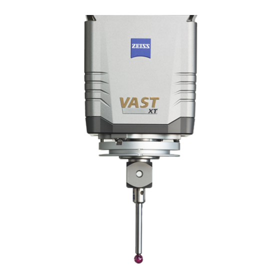
VAST XT gold VAST XT gold Product photo VAST XT gold probe Application The VAST XT gold probe is an actively measuring scanning probe. The probe can be used universally. Measurements performed with this sys- tem provide information on the dimensions, location, and form of a workpiece. -
Page 46: Components
VAST XT gold Components A Probe B Stylus system (adapter plate, extension and stylus) 1 Adapter plate receptacle 2 Pin for positioning the stylus system adapter plate The VAST adapter plate is provided with a distributor with five threaded holes used for mounting stylus system components. The size of the con- nection thread is M5. -
Page 47: Limit Values
VAST XT gold Limit values A maximum weight of 500 g can be suspended from the adapter plate receptacle including the adapter plate. The length of the stylus system including extension must not exceed 500 mm. Tilting moment The maximum tilting moment of the stylus system allowed is 0.3 Nm. See [ ⇨... -
Page 48: Vast Xtr Gold
VAST XTR gold VAST XTR gold Product photo VAST XTR gold probe Application The VAST XTR gold probe is an actively measuring scanning probe. The probe can be used universally. Measurements performed with this sys- tem provide information on the dimensions, location, and form of a workpiece. -
Page 49: System Requirements
VAST XTR gold System requirements To perform measurements using the probe, the following requirements must be met: Measuring software: from CALYPSO 5.2.14 Firmware: from C99 26.12 Components A Probe B Stylus system (adapter plate, extension and stylus) 1 Probe adapter on the ram 2 Adapter plate receptacle 3 Rotational axis with pin for securing the adapter plate adapter plate... -
Page 50: Limit Values
VAST XTR gold B Top view 1 Order number 2 Push-buttons for installing and removing the adapter plate (2 buttons) 3 Cube for mounting styli 4 Anchor plate for fastening to the adapter plate receptacle of the probe 5 Contacts for identifying the adapter plate 6 Cylinder rollers NOTE The »ZCR 70«... -
Page 51: Vast Gold
VAST gold VAST gold Product photo VAST gold probe with stylus system Application The VAST gold probe is an actively measuring scanning probe. The probe can be used universally. Measurements performed with this sys- tem provide information on the dimensions, location, and form of a workpiece. -
Page 52: Components
VAST gold – Use of the RST-T temperature sensor – Use of the ZASarticulating stylus The VAST gold probe supports the options VAST navigator and VAST performance. Components A VAST gold Probe B Stylus system with adapter plate 1 Adapter plate receptacle 2 Pin for positioning the adapter plate Adapter plate The VAST adapter plate is provided with a distributor with five threaded... -
Page 53: Limit Values
VAST gold VASTAdapter plate 1 Anchor plate 2 Groove for the pin located in the adapter plate receptacle of the probe. The pin ensures proper positioning of the adapter plate. 3 M5 threaded hole for stylus system components, e.g. styli Limit values The limit values for weight, length and tilting moment of a stylus system must be considered when assembling or mounting the stylus system. -
Page 54: Temperature Sensor Rst-T (Option)
VAST gold Temperature sensor RST-T (option) Application The RST-T is used to measure the temperature of the workpiece surface and the surrounding air. Both measurements can be carried out in an automatic measurement run. Temperature monitoring is thus possible throughout the entire measurement. NOTE The VAST probe is a prerequisite for operating the RST-T. - Page 55 VAST gold Components 1 VAST adapter plate for RST-T 2 Plug 3 Knurled nut for screwing to adapter plate 4 Temperature sensor 5 Exchangeable sensor 3-35 61211-4060102 Contact probing systems...
-
Page 56: Articulating Stylus (Option)
VAST gold Articulating stylus (option) Articulating stylus for 0° orientation The articulating stylus is inserted into the VAST gold adapter plate recep- tacle. An articulating stylus can only be inserted in a specific orientation into the adapter plate receptacle. There are three articulating stylus for three different orientations: 0°, 90°, - 90°. - Page 57 VAST gold A 0° orientation and swivel range ±135° B 90° orientation, stylus on the left side of the ram C -90° orientation, stylus on the right side of the ram Limit values Probe length, max. 200 mm Stylus tip diameter, min. 1 mm The articulating stylus is supplied in a case.
- Page 58 VAST gold 1 Pin wrench 2 Stylus extension REACH CFX 3 3 Stylus 4 Torx key NOTE The Torx key is used to absorb the forces in order to avoid damaging the bearing of the swivel axis. NOTE The stylus system holder ZCR 70 is used for an automatic change of the articulating stylus.
-
Page 59: Tp6
Product photo Renishaw TP6 probe Application The TP6 is a touch-trigger probe. – Discrete points – Probing of hard-to-access locations on the workpiece – Fast probing NOTE The TP6 probe is used on articulating systems. See operating instruc- tions for articulating systems. NOTE The probing force can be adjusted. -
Page 60: System Requirements
System requirements To perform measurements using the TP6 probe, the following require- ments must be met: Controller Horizontal-arm CMM, e.g. CARMET 2, PRO 2, CALENO Probe holder Articulating system: RDS, CSC, and DSC Components TP6 probe with RDS adapter plate A RDS adapter plate for Renishaw probe or Renishaw extension B Renishaw extension for probe C TP6 probe... -
Page 61: Limit Values
NOTE The TP6 probe can also be used on other articulating systems. adapter plate The Renishaw probe or an extension is attached to the RDS adapter plate. In the second case, the probe is attached to the extension. RDS adapter plates for Renishaw probes with M8 thread 1 Groove for positioning the adapter plate in the adapter plate receptacle of the RDS articulating system 2 Anchor plate... -
Page 62: Tp20
TP20 TP20 Product photo TP20 probe with single stylus Application The TP20 is a touch-trigger probe. – Discrete points – Probing of hard-to-access locations on the workpiece – Fast probing – Automatic stylus system change possible – Different probe modules for different probing forces NOTE The TP20 probe is used on articulating systems. -
Page 63: Components
TP20 Controller Horizontal-arm CMM, e.g. CARMET 2, PRO 2, CALENO Probe holder Articulating system: RDS, CSC, and DSC Components TP20 probe with RDS adapter plate A RDS adapter plate for Renishaw probe or Renishaw extension B Renishaw extension for probe C TP20 probe D Stylus with M2 thread 1 Connection for probe or extension... -
Page 64: Limit Values
TP20 RDS adapter plates for Renishaw probes with M8 thread 1 Groove for positioning the adapter plate in the adapter plate receptacle of the RDS articulating system 2 Anchor plate 3 Push-button for releasing the adapter plate from the RDS articulating system 4 Order number of adapter plate 5 Connection of the Renishaw probe or Renishaw extension (M8 thread) 6 Connection to the RDS articulating system... -
Page 65: Stylus Systems
Stylus systems Stylus systems Stylus system components A simple stylus system consists of an adapter plate and a probe. A complex stylus system may consist of several probes, joining elements and extensions. Example for complex stylus systems Stylus combination A distinction is made between stylus system and stylus combination. The stylus system can consist of several stylus combinations. - Page 66 Stylus systems 2 Stylus system NOTE It is basically possible to create a stylus system with several stylus combi- nations. However, certain assembly criteria must be observed to ensure exact measurement. Stylus A stylus consists of a shaft and a stylus tip. Shafts differ with regard to size and material.
-
Page 67: Stylus Tips
Stylus systems Probe kits The stylus system kits contain styli of different sizes and components that can be used to create stylus systems, e.g. connecting elements. There are many different designs of stylus kits. There are small and big stylus kits. Webshop ➤... -
Page 68: Storage Of Stylus Systems
Stylus systems Stylus tip Description Cylinder Cylinders are preferably used for probing thin sheet-metal parts and narrow workpiece edges. Cone Cones are required for two applications: 1. Self-centering probing 2. High-precision probing of specified positions Disk A disk is used for probing deep grooves and large holes. For large holes, a disk offers the advantage of shorter travel paths. - Page 69 Wrap the stylus system in a cloth or lay it on a soft support. This is necessary to protect the adapter plate and stylus tips against being scratched. Special cabinet The stylus systems are hooked into special fixtures. Such a cabinet is available from ZEISS. Stylus cabinet 3-49 61211-4060102 Contact probing systems...
- Page 70 Stylus systems 3-50 61211-4060102 Contact probing systems...
- Page 71 Technical specifications Technical specifications This chapter contains: RST-P ...................... 4-2 XDT TL3 ...................... 4-3 VAST XXT .................... 4-4 VAST XT gold .................... 4-5 VAST XTR gold .................... 4-6 VAST gold .................... 4-7 Renishaw probes .................. 4-8 61211-4060102 Contact probing systems...
-
Page 72: Rst-P
RST-P RST-P Dimensions Diameter 24 mm Length 56 mm Weight 44 g Probe extension, max. 300 mm Probing direction Direction-independent Min. diameter of the stylus tip 0.5 mm Stylus system weight, max. 10 g Stylus system length, max. 90 mm... -
Page 73: Xdt Tl3
XDT TL3 XDT TL3 Dimensions Length 126 mm Diameter 33 mm Weight 162 g Diameter of adapter plate 28 mm Probe extension, max. 100 mm Probing direction Direction-independent Diameter of the stylus tip 0.3 - 8 mm Stylus system weight, max. 15 g (TL3) Stylus system length 30 - 150 mm (TL3) -
Page 74: Vast Xxt
VAST XXT VAST XXT Dimensions Length 126 mm Diameter, max. 33 mm Weight 147 g 162 g 172 g Diameter of adapter plate 28 mm Probe extension, max. 100 mm Probing direction Direction-independent Diameter of the stylus tip 0.3 - 8 mm Stylus system weight, max. -
Page 75: Vast Xt Gold
VAST XT gold VAST XT gold Dimensions Length 91 mm Width 91 mm Height 100 mm Probing directions 6; ±X, ±Y, ±Z Measuring force 0.05 to 1 N / continuous Diameter of adapter plate 70 mm Probe deflection max. ±2 mm Stylus system weight, max. -
Page 76: Vast Xtr Gold
VAST XTR gold VAST XTR gold Dimensions Length 91 mm Width 91 mm Height 100 mm Probing directions 6; ±X, ±Y, ±Z Measuring force 0.05 to 1 N / continuous Diameter of adapter plate 70 mm Probe deflection max. ±2 mm Stylus system weight, max. -
Page 77: Vast Gold
VAST gold VAST gold Dimensions Length 91 mm Width 91 mm Height 200 mm Probing directions 6; ±X, ±Y, ±Z Measuring force 0.05 to 1 N / continuous Diameter of adapter plate 70 mm Probe deflection max. ±5 mm Stylus system weight, max. 800 g/ incl. -
Page 78: Renishaw Probes
Renishaw probes Renishaw probes Type TP20 Dimensions Diameter [mm] 13.2 Length [mm] Weight Extensions, max. [mm] Probing direction ±X, ±Y, -Z ±X, ±Y, -Z Connection thread for probe Connecting thread for stylus including module for probing force. There are several modules for different probing forces. - Page 79 Handling Handling This chapter contains: What you should know!................ 5-2 Notes on measuring operation.............. 5-10 RST-P ...................... 5-11 RST-T ...................... 5-15 VAST XXT .................... 5-17 VAST XTR.................... 5-20 Stylus system assembly................ 5-28 Installing the stylus system ................. 5-35 61211-4060102 Contact probing systems...
-
Page 80: What You Should Know
Discrete-point probing, multipoint measurements, and scanning are pos- sible using the corresponding probing system. When scanning, it is dif- ferentiated between passive and active measuring probing systems: Single point Multiple point Scanning Passive Active RST-P × XDT TL3 × × VAST XXT ×... - Page 81 What you should know! A Before probing B After probing NOTE In case of a fault, the joysticks are re-enabled after about two seconds. The stylus can be moved back via joystick control. The stylus can be moved in all directions at low speed. The collision protection is not ac- tive.
- Page 82 What you should know! Exact measured values With measuring probing systems, many measured values are recorded in each probing. Using these values, the control calculates the exact mea- sured value. This guarantees a low deviation and a high reproducibility, even in case of high travel speeds and disturbance variables from out- side, e.g.
- Page 83 What you should know! Active scanning During active scanning, the surface of a workpiece is continuously probed. The measuring points make it possible to calculate surfaces or provide information on the form of a surface. NOTE By selecting the scanning mode, it is possible to influence the stylus de- flection and the measuring accuracy.
-
Page 84: Special Features Of The Measuring Probing System
What you should know! Passive scanning During probing by means of the stylus tip, a spring element in the probe is deflected which generates the measuring force. Special features of the measuring probing system Notes on measuring probing systems The results of manual probings and automatic measuring runs may slightly differ from each other. - Page 85 What you should know! Deformation of the workpiece A Nominal condition: no workpiece deformation. B Falsified measurement due to deformation of the workpiece. Reason: soft mate- rial and high measuring force. 1 Extent of falsification Measurement values can also be falsified by the stylus bend, especially when long and thin probes are used.
- Page 86 What you should know! NOTE With self-centering probing, a higher measuring force in the MAN oper- ating mode might be useful in order to improve centering. See — Increase the measuring force if necessary. Probe-specific information Adjustments of the measuring force and further particularities for the measuring operation of specific probes are treated elsewhere.
- Page 87 What you should know! For information on how to remove aluminum deposits, please refer to the operating instructions for the CMM. 2 If the stylus tip is damaged, you must replace the stylus. 61211-4060102 Contact probing systems...
-
Page 88: Notes On Measuring Operation
Notes on measuring operation Notes on measuring operation Checking the styli Regular inspection of the stylus systems is required to ensure correct workpiece measurement. — Check the styli, the stylus system components and the adapter plate regularly. — Remove any particles or grease film from the stylus tips and the adapter plate. -
Page 89: Rst-P
RST-P RST-P Admissible zone for the stylus 44 54 A Admissible zone for the stylus B Limited central zone for reverse probings 1 Lateral 2 Reverse 3 Next 4 Data in mm Admissible zone [A] When probing forwards and sidewards, all stylus systems are admissi- ble, in which the styli are arranged within the drawn semicircular area. -
Page 90: Inadmissible Zone For Reverse Probings
5 Probe Probing may be critical if the following four criteria coincide: – Use of an extension that is longer than 200 mm for the RST-P probe. – Surface normal at the probing point points to the center of the bear- ing plane, in the range of ±... - Page 91 4 Center of the bearing plane for the RST-P probe Damage to the probe during reverse probing. The bearing plane for the RST-P probe must not be loaded in the direc- tion of pull. This may happen during reverse probings if the surface nor- mal of the workpiece to be probed is superimposed on the stylus vec- tor.
- Page 92 Stylus vector outside the inadmissible zone Stylus vector within the inadmissible zone Surface normal of the workpiece in the probing point Inadmissible zone: 60° cone around the surface normal Center of the bearing plane for the RST-P probe 5-14 61211-4060102 Contact probing systems...
-
Page 93: Rst-T
RST-T RST-T Notes on temperature measurement – The temperature measurement should be carried out on thick-walled workpieces. – The workpiece surface must be clean and flat. – The surface being probed should be larger than the contact surface of the sensor. –... -
Page 94: Field Of Application
RST-T Field of application With a RST-T, you have the following options: – To carry out a temperature compensation. – To use the temperature probe in an automatic measuring run. – To monitor the temperature. – To check the temperature. –... -
Page 95: Vast Xxt
VAST XXT VAST XXT Dead-weight offset Since the VAST XXT is not provided with the counterbalancing function, the stylus sags down, more or less, depending on the weight and orien- tation of the probe. The resulting display on the probe-internal path measurement system is called dead-weight offset (DWO). - Page 96 VAST XXT Modes for critical application cases: Sensitive: Small deflection, for example for soft workpieces or low scanning speed. Robust: High deflection, for example for rough workpieces or high scanning speed. The different modes can be selected in CALYPSO. Qualification NOTE The shaft of the reference sphere may not be probed during the qualifi- cation.
- Page 97 VAST XXT – Disk styli may not be used since those cannot be qualified. Requirements for very small styli Styli with a stylus tip diameter of 0.1 mm can be used on the O-INSPECT. The following CALYPSO settings are recommended for styli diameters of less than 0.3 mm: Requirements for qualification: Probe...
-
Page 98: Vast Xtr
VAST XTR VAST XTR Configuring the probe Configuring probe and holder in the measuring software In the CALYPSO default settings, the probe must be set on the »Sensors« tab. To do so, select »VAST-XTR«. When creating a new stylus system holder, select the »ZCR«... - Page 99 VAST XTR Mounting a holder between two existing holders Qualification The holder can be qualified using any qualified stylus. The only condition is that the max. diameter of the stylus tip is 8 mm. Qualification is a two-step procedure: 1. The stylus length must be determined. To do so, probe any plane surface with the stylus tip and with the lower edge of the adapter plate.
-
Page 100: Installing And Removing The Adapter Plate
VAST XTR 1 Sloped qualification surface NOTE The adapter plate can only be stored in one holder position. For this, the adapter plate is rotated automatically to the corresponding position. The holders can be arranged such that approach in the ±X and ±Y di- rections is possible. - Page 101 VAST XTR NOTE After manual change of the adapter plate, make sure that both push- buttons return to their initial position. Otherwise, the adapter plate may not be recognized correctly in the system. Neither rotation nor probing is possible in this position. The current angular position of the adapter plates is automatically recog- nized after correct loading.
-
Page 102: Collision Protection
VAST XTR Removing the adapter plate The procedure for manual removal of the adapter plate is initiated by a command via the control console or a software command. At the same time, the two push-buttons of the adapter plate must be pressed and kept pressed. -
Page 103: Use Of Other Adapter Plates
VAST XTR Subsequent measures: 1. After more than 3 collisions, insert new annular springs in the groove of the anchor plate [1, 2]. 2. Reinsert the locking slides [3], making sure they are properly aligned. NOTICE! The beveled surfaces of the locking slides must point downwards. - Page 104 VAST XTR VAST adapter plate with DataMatrix code 1 Groove for proper positioning in the adapter plate receptacle 2 DataMatrix code Collision protection Before using VAST adapter plates, the collision protection ring must be pressed onto the adapter plate. NOTICE! Otherwise, no collision protection is provided for the VAST XTR gold.
- Page 105 VAST XTR NOTE If the adapter plate is accidentally inserted in the wrong position, it will not be recognized. In this case, the adapter plate must be released and installed again. 5-27 61211-4060102 Contact probing systems...
-
Page 106: Stylus System Assembly
Stylus system assembly Stylus system assembly Precautions Probe holder Damage to the probe holder due to forces exerted during in- stallation of the styli. Stylus systems must not be assembled on the probe. — Do not attach any styli to the probe as long as probing system is in- serted in the adapter plate receptacle. -
Page 107: Information On The Assembly
— When mounting styli, use the supplied auxiliary tool to fasten the joint. Probe extensions NOTE Only one-piece ZEISS extensions may be used for probe extensions ex- ceeding 300 mm. Multiple-piece extensions are not permitted. Information on the assembly There are two ways to assemble a stylus system: 1. -
Page 108: Criteria And Limit Values
Depending on the probing system, different thread sizes are used: M2, M3 and M5. Thread sizes: VAST XT gold,VAST XTR gold, VAST gold RST-P, XDT TL3, VAST XXT M2, M3 Renishaw probes The stylus system components differ with regard to material and geome- try, e.g. - Page 109 Stylus system assembly – Symmetrical design with respect to weight; the center of gravity must be located in the physical center; use counterweights if neces- sary. Stylus extensions may be used as counterweights. Note: Check the balance by holding the adapter plate between two fingers and letting the stylus system swing back and forth until it comes to a stop.
- Page 110 NOTE The limit values for the maximum weight refer to the stylus system and adapter plate. For some probes, there is no adapter plate, for example for the RST-P. Calculation of the tilting moment: The tilting moment K can be calculated as follows:...
-
Page 111: Example
Stylus system assembly L Distance between the center of gravity and the bisecting line Example Connecting parts are normally needed to assemble the required stylus systems. It is also possible to screw the stylus directly into the adapter plate. Assembly example, applying the threaded-joint technology with the VAST adapter plate: A Stylus in the adapter plate B Extension in adapter plate... - Page 112 Stylus system assembly VAST adapter plate 1 Screws 2 Insert the stylus system in the adapter plate receptacle. 3 Rotate the stylus system to the required position. 4 Hold the stylus system and take it out of the adapter plate recepta- cle.
-
Page 113: Installing The Stylus System
Installing the stylus system Installing the stylus system Precautions The stylus system is held in place by an magnetic spring system. If the measuring software calls for an insertion or change of the stylus system, the magnetic force is adapted electrically. After insertion of the stylus system, the full holding force becomes effective after a short delay. -
Page 114: Removing The Stylus System (Manually)
Installing the stylus system The pin must engage in the notch. See drawing. The stylus system is attracted by the magnet. The stylus system installation is complete, if there has been an audible click. 1 Pin in the adapter plate receptacle of the probe 2 Groove in the adapter plate 3 Push-button for releasing the safety catch. - Page 115 – Hold the stylus system below the adapter plate and tilt it to the side. RST-P The stylus system must be deflected manually. This re- leases the magnet in the RDS adapter plate receptacle. Adapter plate of articulating systems The adapter plate is locked.
- Page 116 Installing the stylus system 5-38 61211-4060102 Contact probing systems...
-
Page 117: Chapter 6 Errors And Malfunctions
Errors and Malfunctions Errors and Malfunctions This chapter contains: Faults during operation ................ 6-2 61211-4060102 Contact probing systems... -
Page 118: Faults During Operation
Faults during operation Faults during operation Error Cause Remedy The power LED on the RDS The contacts of the adapter plate – Check and, if necessary, clean adapter plate does not light are defective or soiled. the contacts. The system clock pulse LED CAN bus error –... - Page 119 Faults during operation 1 LED for probe: The LED is permanently on if the probe has been installed in the adapter plate and if the adapter plate is fitted in the RDS adapter plate recepta- cle. 2 System clock pulse LED 3 Power LED: The LED is permanently on.
- Page 120 Faults during operation 61211-4060102 Contact probing systems...
-
Page 121: Chapter 7 Care And Inspection
Care and inspection Care and inspection This chapter contains: What you should know! ................ 7-2 Inspection measures .................. 7-3 Care and cleaning .................. 7-4 61211-4060102 Contact probing systems... -
Page 122: What You Should Know
What you should know! What you should know! The sensitive measuring system of the CMM requires a certain degree of cleanliness. Even the smallest dust particles on the stylus tip or the refer- ence sphere may cause inaccurate measurements. Cleaning agent: Material Purpose Mild cleaning agent... -
Page 123: Inspection Measures
Inspection measures Inspection measures Checking the stylus system Regular inspection of the stylus systems is required to ensure correct workpiece measurement. 1 Check the styli at regular intervals. 2 Remove any particles or grease film from stylus tips. 3 Replace a damaged stylus. 61211-4060102 Contact probing systems... -
Page 124: Care And Cleaning
Care and cleaning Care and cleaning Stylus tips Stylus tips may be contaminated, e.g. by dust particles. Furthermore, material from the probed workpiece may accumulate on the stylus tip, especially during scanning. NOTE The styli must be handled carefully. If force is applied, the bond be- tween the stylus tip and the stylus shaft may break and the stylus shaft may bend or even break. - Page 125 Care and cleaning NOTE Ensure that there is no cleaning agent residue. This could impair the function of the adapter plate. Probe The adapter plate and the adapter plate receptacle of the probe must be protected against dirt. – Place a protective cap on the adapter plate receptacle of the probe when there is no stylus system in the adapter plate receptacle or the probe is not in use.
- Page 126 Care and cleaning 61211-4060102 Contact probing systems...
-
Page 127: Chapter 8 Disposal
Disposal Disposal This chapter contains: Package ....................... 8-2 Disposal of probing systems ................. 8-3 61211-4060102 Contact probing systems... -
Page 128: Package
Package Package The regulations of the country in which the CMM is installed apply to the disposal of the packaging material. 61211-4060102 Contact probing systems... -
Page 129: Disposal Of Probing Systems
Disposal of probing systems Disposal of probing systems Some parts of the probing system contain electronic components and must not be disposed of with domestic waste. Make sure to dispose of the components in question in accordance with the WEEE directive 2012/19/EU or the respective country-specific legislation applicable within the EU states. - Page 130 Disposal of probing systems 61211-4060102 Contact probing systems...
-
Page 131: Glossary
Glossary Term Explanation CAN bus Asynchronous, serial bus system (CAN: acronym for »Local Area Network«) CFRP Acronym for »Carbon Fiber Reinforced Polymer« 61211-4060102 Contact probing systems Glossary... - Page 132 61211-4060102 Contact probing systems Glossary...
-
Page 133: Index
Index Adapter Environmental conditions VAST XXT 3-18 Renishaw probe 4-8 XDT TL3 3-11 RST-P 4-2 Adapter plate VAST gold 4-7 Care 7-4 VAST XT gold 4-5 Function 3-4 VAST XTR gold 4-6 TP20 3-43 VAST XXT 4-4 TP6 3-41 XDT TL3 4-3 VAST 3-26, 3-32 Extension VAST XTR gold 3-29 Stylus 3-46 Aluminum deposits Removal 7-4 Articulating stylus 3-36 Fine positioning 5-6... - Page 134 REACH 3-46 Removing 5-36 Renishaw Storage 3-48 Limit values 3-41, 3-44 Stylus 3-46 Technical data 4-8 Stylus kit 5-30 TP20 3-42 Stylus tip TP6 3-39 Aluminum deposits 7-4 RST-P Care 7-4 Admissible zone for stylus tips 5-11 Stylus tips 3-47 Application 3-6 Application 3-47 Components 3-7 System requirements Critical probings 5-11 XDT TL3 3-9 Extensions 3-7 System safety 1-3 Limit values 3-7 Technical data 4-2...
- Page 135 VAST XT gold 3-25 Application 3-25 Technical specifications Components 3-26 Renishaw probes 4-8 Limit values 3-27 Temperature measurement Technical data 4-5 RST-T 5-15 VAST XTR gold 3-28 Temperature sensor 3-34 Adapter plate 3-29 Application 3-34 Application 3-28 Temperature measurement with RST- Collision protection 5-24 T 5-15 Components 3-29 Threaded-joint technology Inserting the adapter plate 5-22 Example 5-33 Limit values 3-30 Tilting moment Setting up 5-20...
- Page 136 XDT TL3 Adapter 3-11 Adapter plate receptacle 3-11 Application 3-9 Components 3-11 Extensions 3-14 Limit values 3-13 System requirements 3-9 technische Daten 4-3 Version 3-10 ZAS 3-36 61211-4060102 Contact probing systems Index...
-
Page 137: Appendix
Appendix Appendix This chapter contains: Webshop.................. Appendix 2 Order numbers ................ Appendix 3 61211-4060102 Contact probing systems Appendix... -
Page 138: Webshop
Examples: styli, extensions, adapter plates. – CMM accessories Examples: changer racks, clamping devices, reference spheres. – Training material Examples: books, learning videos. If the desired component is not available in the webshop, please contact the support. https://shop.metrology.zeiss.de 61211-4060102 Contact probing systems Appendix... -
Page 139: Order Numbers
Order numbers Order numbers Below you will find some order numbers of components. Version: 2020-12. Supplementary components for VAST gold: Component Order number RST-T temperature sensor 600661-9675-000 Replacement sensor for RST-T 600661-8600-000 RST-T adapter plate 600667-9603-000 Order numbers for VAST XTR gold: Component Order number VAST XTR gold adapter plate... - Page 140 Order numbers Extensions Extensions for RST-P and VAST XXT: Material Length Order number Note CFRP 60 mm 600661-8420-000 CFRP 100 mm 600661-8421-000 CFRP 200 mm 600661-8422-000 Only for RST-P CFRP 300 mm 600661-8423-000 Only for RST-P 61211-4060102 Contact probing systems...
- Page 142 Contact probing systems Operating Instructions 2021-09-01 61211-4060102...
Need help?
Do you have a question about the RST-P and is the answer not in the manual?
Questions and answers