
Subscribe to Our Youtube Channel
Related Manuals for Ochsner AIR FALCON 212 C11A T200


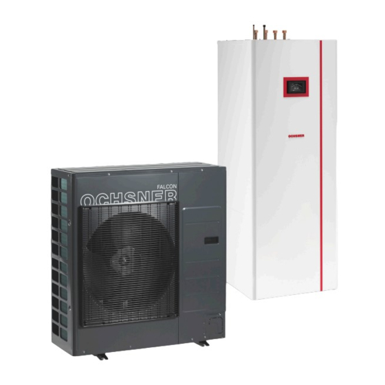
Summary of Contents for Ochsner AIR FALCON 212 C11A T200
- Page 1 HIGH EFFICIENCY AIR/WATER HEAT PUMPS DESIGN AND INSTALLATION MANUAL ► AIR FALCON 212 C11A T200 ► AIR FALCON 212 C11B T200 ► AIR FALCON 212 C11B T201 TRANSLATION OF THE ORIGINAL MANUAL...
- Page 2 | PIA-982043-AIR FALCON-T200-ih-EN...
-
Page 3: Table Of Contents
12.1 Requirements Indoor unit 12.2 System completion Installation location 12.3 Commissioning the system Keep minimum clearances 12.3.1 Activities carried out by OCHSNER Machine-specific engineering and preparation SPECIFICATION Outdoor unit Data table 8.1.1 Installation location 13.1 Controller outputs 8.1.2 Minimum clearances 13.2... -
Page 4: Please Note
OCHSNER homepage in the download area. ► Observe all applicable national and regional regula- Safety information tions and provisions. -
Page 5: Keywords
For this reason, the stated perfor- mance figures can differ from plant-specific performance data. PIA-982043-AIR FALCON-T200-sh-EN | www.ochsner.com... -
Page 6: Safety
The noise is caused by chang- ► Commissioning of the appliance may be carried out es in the compressor speed. only by OCHSNER Customer Service or by customer service partners authorised by OCHSNER. ► The qualified contractor is responsible for compliance with all relevant regulations during installation and commissioning. - Page 7 Safety PIA-982043-AIR FALCON-T200-sh-EN | www.ochsner.com...
-
Page 8: How Split Systems Work
The outdoor air is routed through the outdoor unit by means of a fan. The indoor and outdoor units are connected through refrigerant lines. Due to the defrosting mode integrated into OCHSNER air/ water heat pumps, the system also operates flawlessly at temperatures below -15°C. - Page 9 How split systems work 00_400_200_202_01_split_Funktionsweise-EN | www.ochsner.com...
-
Page 10: Device Description
The indoor unit is intended to be installed inside the build- ing only. The casing is acoustically optimised and allows particularly quiet operation. The system must be engineered using an OCHSNER standard hydraulic schematic or an OCHSNER special hydraulic system. -
Page 11: Outdoor Unit
The buffer tank and the DHW tank with heat exchanger are arranged on top of each other and can be separated The evaporator is part of the outdoor unit and consists of for handling. copper pipes in a set of aluminium fins. 00_200_202_08_02_002-EN | www.ochsner.com... -
Page 12: Heat Pump Control Unit
Name plate To identify your heat pump, name plates are attached to the indoor and outdoor unit. ► The type plate on the indoor unit is located on the side casing panel. 1 Name plate on outdoor unit www.ochsner.com | 00_200_202_08_02_002-EN... - Page 13 Device description 00_200_202_08_02_002-EN | www.ochsner.com...
-
Page 14: Engineering Of Asplit System
High wind loads on the outdoor unit can cause problems with defrosting in defrosting mode. Avoid installation in an open and exposed location with high expected wind loads (e.g. flat roof of a house in a raised location). www.ochsner.com | 00_400_200_202_02_split_Planung_Errichtung-EN... -
Page 15: Sound
Plants and cultivated areas around the outdoor unit, subject to minimum clearances, can reduce its noise level. Note The maximum permitted sound levels are partly subject to legal limitations. » Observe all applicable national and regional regulations and provisions. 00_400_200_202_02_split_Planung_Errichtung-EN | www.ochsner.com... -
Page 16: Refrigerant Lines
Preparing the refrigerant lines Note Note Appropriate copper pipes for refrigerant lines are Only OCHSNER customer service or authorised supplied sealed at both ends and filled with nitro- OCHSNER customer service partners may con- gen. nect the refrigerant lines to the indoor and outdoor units. -
Page 17: Refrigerant Pipes Passing Through Open Air
UV protection. Note Where the refrigerant pipes run horizontally through open air, use suitable supports. Take steps to pre- vent above-ground refrigerant pipes from being walked or driven on. 00_400_200_202_02_split_Planung_Errichtung-EN | www.ochsner.com... -
Page 18: Wall Conduit
» on both the outer and inner edge of the wall. Allow some surplus length in the refrigerant pipes between the connections at the indoor and outdoor units. www.ochsner.com | 00_400_200_202_02_split_Planung_Errichtung-EN... -
Page 19: Indoor Unit
That it operates fault-free ► Ability to carry out maintenance on the appliance » Observe the machine-specific minimum clearances. Note The machine-specific information on engineering and preparation can be found in this document‘s machine-specific engineering and preparation sec- tion. 00_400_200_202_02_split_Planung_Errichtung-EN | www.ochsner.com... -
Page 20: Machine-Specific Engineering And Preparation
1 Wind direction ► The outdoor unit should be positioned with the air outlet side facing a wall, ensuring that minimum clear- ances are observed; this protects the air outlet side from direct exposure to winds. www.ochsner.com | 00_200_202_08_01_002-EN... - Page 21 ► The mounting feet of the outdoor unit must be at least 80 mm clear of the surrounding terrain. 00_200_202_08_01_002-EN | www.ochsner.com...
-
Page 22: Installation In Coastal Areas
(every three months) » 1 Sea During extended periods of downtime, ensure 2 Sea breeze that the outdoor unit is appropriately protect- 3 Outdoor unit 4 Building 5 Protective wall 8.1.4 Foundations for the outdoor unit www.ochsner.com | 00_200_202_08_01_002-EN... - Page 23 3 Level of surrounding terrain AIR FALCON 212 AIR FALCON 212 Installing strip foundations When laying strip foundations we recommend the following approach: » Dig out the foundation trench. » Place a drainage pipe along the base of the trench. 00_200_202_08_01_002-EN | www.ochsner.com...
-
Page 24: Wall Mounting
Install the insulating plates between the outdoor unit build-up of ice. and the wall bracket and between the wall bracket and the wall to reduce the transmission of noise and vibration to the building. www.ochsner.com | 00_200_202_08_01_002-EN... -
Page 25: Drainage
2 Refrigerant lines routed into the outdoor unit from the AIR FALCON 212 ≤ 20 m ≤ 15 m back 3 Pipe liner for underground connecting lines 4 Refrigerant lines routed into the outdoor unit from the front 00_200_202_08_01_002-EN | www.ochsner.com... -
Page 26: Material Requirements
Maximum 8x90° bending radii ► Use suitable fittings for bends ► Bending radii of ≥ 1 m are considered as straight runs Hot gas line Copper pipes Requirement Diameter AIR FALCON R220 (soft, in rings) to EN 16x1 12735-1 www.ochsner.com | 00_200_202_08_01_002-EN... -
Page 27: Indoor Unit
» Make sure that the power supply for this Connection line length Min. clear floor space appliance is separate from the domestic in- stallation. » 16.7 Install a type B, AC/DC-sensitive RCD. 16.7 00_200_202_08_01_002-EN | www.ochsner.com... -
Page 28: Heat Pumps For Three-Phase Power Supply
► For the integral electric auxiliary heater, a suitable high limit safety cut-out (HLSC) is installed in the in- door unit. www.ochsner.com | 00_200_202_08_01_002-EN... -
Page 29: Heat Pumps For Single-Phase Power Supply
(on the north-west side) at a height of Connections RJ45 connector approx. 2.5 m. Make sure that the outdoor tempera- ture sensor is not exposed to direct sunlight or wind, as this will impair the control characteristics. 00_200_202_08_01_002-EN | www.ochsner.com... -
Page 30: Pumps And Servomotors
Shutdown by means of a tariff contactor In the case of shutdown by means of a tariff contactor installed on site (sealed by the PSU), the power supply to the heat pump compressor is disconnected. Here, it is es- www.ochsner.com | 00_200_202_08_01_002-EN... - Page 31 00_200_202_08_01_002-EN | www.ochsner.com...
-
Page 32: Installation
The appliance may be stored and transported only at Use the recessed handles on the bottom and back of temperatures of between -20°C and +45°C. the appliance for better grip during transportation. ► The appliance must be stored in its transport packaging. www.ochsner.com | PIA-982043-AIR FALCON-T200-in-EN... -
Page 33: Positioning The Appliance
Removing the top appliance casing » Undo and remove the screws on the top of the casing. » Remove the top appliance cladding. » Remove the thermal insulation material underneath. » Disconnect the touchscreen communication cable plug from the controller. PIA-982043-AIR FALCON-T200-in-EN | www.ochsner.com... -
Page 34: Assembling The Appliance Casing
Separating the appliance sections » Remove the 4 hydraulic hoses and the thermal insula- » Pull out the heating sensor from the buffer tank. tion element. » Remove the sensor cable from the guiding groove in the insulation element. www.ochsner.com | PIA-982043-AIR FALCON-T200-in-EN... -
Page 35: Assembling The Appliance Sections
9.1.6 Assembling the appliance sections Assemble the appliance sections in reverse order. The positioning aids and dotted line markings facilitate positioning and sliding the top appliance section into the guiding groove on the lower section: PIA-982043-AIR FALCON-T200-in-EN | www.ochsner.com... -
Page 36: Installing The Outdoor Unit
The appliance must be stored in its transport packaging. ► When transporting with a crane, the outdoor unit must be secured with two 8 m long ropes. Use strips of fabric to protect the appliance from scratches. www.ochsner.com | PIA-982043-AIR FALCON-T200-in-EN... -
Page 37: Positioning The Appliance
Push out the corresponding perforated plate depend- Note ing on the required exit direction for cables and lines. The outdoor unit must be firmly bolted to the foun- dation to ensure that it cannot tip over due to wind. PIA-982043-AIR FALCON-T200-in-EN | www.ochsner.com... -
Page 38: Connecting The Heat Sink System
A heating protection filter must be installed in the re- » turn line of the heat pump to catch dirt. Ensure that the connection is tight. » When installing pipework, take care to prevent trans- mission of vibration noise. www.ochsner.com | PIA-982043-AIR FALCON-T200-in-EN... -
Page 39: Quality Of Heating Water
The cable from the 3-way switching module to the controller has been disconnected at the factory. » After filling, plug the connector into the 3-way switching module. PIA-982043-AIR FALCON-T200-in-EN | www.ochsner.com... -
Page 40: Cooling Version
16 DHW outlet (heat pump) DHW system. 17 Temperature and pressure relief valve (heat pump) 18 Discharge pipe D1 (from temperature and pressure relief valve to tundish) 19 Expansion vessel 20 Expansion valve Minimum size of the discharge pipe D1 www.ochsner.com | PIA-982043-AIR FALCON-T200-in-EN... -
Page 41: Dhw System Safety Valve Drain
Version 2: » Carry out a leakage test. » Remove the appliance cladding. (See page 33, » Test the safety valve. Disassembling the appliance casing) » To vent the system, temporarily open the air vent valve. PIA-982043-AIR FALCON-T200-in-EN | www.ochsner.com... -
Page 42: Heating Circuit With Mixing Valve
- Nominal diameter DN 25 (1”) that subsequent connection work and soldering on the refrigerant pipes will not be obstructed by the ► The adaptor is available from OCHSNER as an cables. accessory. Subsequently, the heating circuit can be set up externally. - Page 43 KNX connection Room temperature sensor » Connect the power supply cable for the controller Heat source system bus WQA-BUS supply. Connection between indoor and outdoor unit » Connect the power supply for the electric auxiliary heater. PIA-982043-AIR FALCON-T200-in-EN | www.ochsner.com...
- Page 44 Controller outputs Abbreviations Description PSU signal contact STB-PUM-HK1 High limit safety cut-out, pump, heating circuit 1 Abbreviations Description MIV-HK2 Mixed circuit valve, heating cir- cuit 2 PUM-HK2 Pump, heating circuit 2 PUM-HK1 Pump, heating circuit 1 www.ochsner.com | PIA-982043-AIR FALCON-T200-in-EN...
-
Page 45: Electrical Connection Of The Outdoor Unit
When laying the cables to the outdoor unit, ensure that no water can flow into the protective sleeve. 10.4 LAN connection » Make sure you have a stable internet connection to the heat pump. PIA-982043-AIR FALCON-T200-in-EN | www.ochsner.com... -
Page 46: Initial Start-Up
Make sure that the heat sink system (heating and DHW heating) has been connected to the heat pump. » Make sure that the hydraulic system is filled with water. » Make sure that the electrical installation has been carried out and completed professionally. www.ochsner.com | PIA-982043-AIR FALCON-T200-in-EN... - Page 47 PIA-982043-AIR FALCON-T200-in-EN | www.ochsner.com...
-
Page 48: Completion And Commissioning
NER guidelines. ► The system temperature or the buffer tem- Note perature must be at least 15°C at the time of OCHSNER accepts no liability for damage (e.g. to commissioning. plate heat exchangers) caused by poor water qual- Note ity. -
Page 49: System Completion
WARNING: Burns tem user during the commissioning. Work on the refrigerant circuit may be carried out only by OCHSNER Customer Service or by cus- ► Customer-specific controller settings are available tomer service partners authorised by OCHSNER. - Page 50 (in countries where the Pressure Equipment Directive 2014/68/EU is valid). Note If the system is not commissioned by OCHSNER customer service, but by a customer service part- ner authorised by OCHSNER, a declaration of conformity in line with Pressure Equipment Direc- tive 2014/68/EU must be issued by this partner.
- Page 51 00_400_01_01-EN | www.ochsner.com...
-
Page 52: Specification
Sound power level (EN12102) / Sound pressure level dB(A) 52 / 35 Silent mode 52 / 35 Silent mode 52 / 35 Silent mode (at 3 m) Evaporator type Finned tube Finned tube Finned tube Evaporator material (WQA) Copper/aluminium Copper/aluminium Copper/aluminium www.ochsner.com | PIA-982043-AIR FALCON-T200-td-EN... - Page 53 AIR FALCON 212 C11B T200 T200 T201 Refrigerant Refrigerant charge Max. refrigerant operating pressure Compressor type Rotary piston Rotary piston Rotary piston Defrost technology Refrigerant circuit reversal Refrigerant circuit reversal Refrigerant circuit reversal PIA-982043-AIR FALCON-T200-td-EN | www.ochsner.com...
- Page 54 Energy efficiency class (D to A+++) P rated Efficiency ETAs 164.3 120.1 164.3 120.1 164.3 120.1 SCOP 4.18 3.08 4.18 3.08 4.18 3.08 at min. flow temperature (cooling) °C SEER 5.16 5.16 5.16 www.ochsner.com | PIA-982043-AIR FALCON-T200-td-EN...
-
Page 55: Controller Outputs
1 Residual pump head, max. output (stage 3) 2 Residual pump head, average output (stage 2) 13.3 Temperature sensor pressure drop curve Temperature Resistance °C Ω 803.1 842.7 882.2 921.6 960.9 1000 1039 1077.9 1097.4 1116.7 1155.4 1194 1232.4 PIA-982043-AIR FALCON-T200-td-EN | www.ochsner.com... -
Page 56: Pump Curve
Pump curve 14. Pump curve 14.2 Heating circulation pump 14.1 Buffer charging pump 15. Limits of use for heating X Outdoor temperature [°C] Y Flow temperature [°C] 1 Maximum design flow temperature www.ochsner.com | PIA-982043-AIR FALCON-T200-td-EN... -
Page 57: Limits Of Use For Cooling
Pmax 35°C = max. output at 35°C flow Pmax 55°C = max. output at 55°C flow Heating output at standard outdoor temperature: (max. output at 35°C flow) Outdoor air temperature [°C] Heating output [kW] 6.81 7.07 7.32 7.57 7.83 8.08 8.33 8.59 8.84 PIA-982043-AIR FALCON-T200-td-EN | www.ochsner.com... -
Page 58: System Principle Schematic
9 Heat source system error signal A Power supply, heat source system for three-phase power supply B Power supply, heat source system for single-phase power supply C Indoor unit control box D Indoor unit E Room temperature sensor F Outdoor unit www.ochsner.com | PIA-982043-AIR FALCON-T200-td-EN... - Page 59 A Power supply, heat source system for three-phase power supply B Power supply, heat source system for single-phase power supply C Indoor unit control box D Heating circulation pump adaptor E Indoor unit F Room temperature sensor G Outdoor unit PIA-982043-AIR FALCON-T200-td-EN | www.ochsner.com...
-
Page 60: Voltage Quality In Isolated Mode
Total harmonic content (THC) 8% ► Frequency 49.5 Hz to 50.5 Hz ► Slow voltage changes 230 VAC ± 10% (integration interval 10 min) ► Rapid voltage changes 230 VAC ± 5% (integration interval 10 ms) ► Voltage asymmetry 2% www.ochsner.com | PIA-982043-AIR FALCON-T200-td-EN... -
Page 61: Dimensions And Connections
20.1 Indoor unit 20.1.1 T200 1 Liquid line (refrigerant) 2 Hot gas line (refrigerant) 3 Heating water flow 4 Cold water inlet 5 DHW outlet 6 Heating water return 7 Safety valve drain 8 DHW circulation PIA-982043-AIR FALCON-T200-td-EN | www.ochsner.com... -
Page 62: T201
1 Liquid line (refrigerant) 2 Hot gas line (refrigerant) 3 Heating water flow 4 Cold water inlet 5 DHW outlet 6 Heating water return 7 Safety valve drain 8 DHW circulation 9 Temperature and pressure relief valve www.ochsner.com | PIA-982043-AIR FALCON-T200-td-EN... -
Page 63: Outdoor Unit
Dimensions and connections 20.2 Outdoor unit 1 Liquid line (refrigerant) 2 Hot gas line (refrigerant) 3 Pipe entry points 4 Drainage holes PIA-982043-AIR FALCON-T200-td-EN | www.ochsner.com... -
Page 64: Drainage Plug
Dimensions and connections 20.2.1 Drainage plug www.ochsner.com | PIA-982043-AIR FALCON-T200-td-EN... - Page 65 PIA-982043-AIR FALCON-T200-td-EN | www.ochsner.com...
-
Page 66: Environment And Recycling
R32 refrigerant is a fluorinated greenhouse gas listed in the Kyoto Protocol. R32 refrigerant must not be discharged into the atmosphere. Note The refrigerant used is assigned to safety class A2L. It is not harmful to the environment and is of low flammability. www.ochsner.com | PIA_982043_AIR_FALCON_T200_EN06.1... - Page 67 PIA_982043_AIR_FALCON_T200_EN06.1 | www.ochsner.com...
- Page 68 Customer service hotline: +41 (0) 800 100 911 kontakt@ochsner.at kontakt@ochsner.de kontakt@ochsner.com www.ochsner.com www.ochsner.com www.ochsner.com Head Office/Factory OCHSNER East Ochsner-Strasse 1 PL 31-302 Kraków 3350 Haag ul. Pod Fortem Nr. 19 Austria Tel.: +48 (0)12 4214527 Hotline for system partners: +43 (0) 820 201020 kontakt@ochsner.pl...
Need help?
Do you have a question about the AIR FALCON 212 C11A T200 and is the answer not in the manual?
Questions and answers