Craftex CX Series User Manual
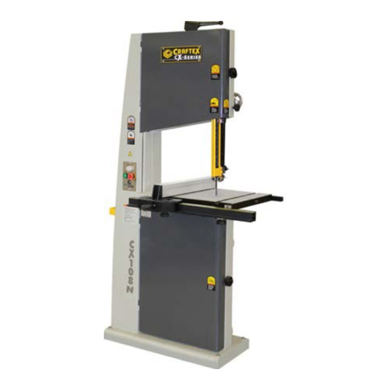
18” wood band saw
Hide thumbs
Also See for CX Series:
- User manual (49 pages) ,
- Manual (42 pages) ,
- Owner's manual (35 pages)
Table of Contents
Advertisement
Quick Links
Advertisement
Table of Contents

Subscribe to Our Youtube Channel
Related Manuals for Craftex CX Series


Summary of Contents for Craftex CX Series
- Page 1 CX108N 18” WOOD BAND SAW User Manual Version 1.0...
-
Page 2: Table Of Contents
TABLE OF CONTENTS General Safety Instructions ..................3 Specific Safety Instructions ..................Features ........................Physical Features ....................Setup ....................... 7 Un-packing ......................7 Proper Grounding ....................8 Assembly and Adjustments ................9 Blade Tracking ......................12 Basic Controls ......................13 Test Run ........................ -
Page 3: General Safety Instructions
GENERAL SAFETY INSTRUCTIONS Extreme caution should be used when operating all machinery. Know your machine, be familiar with its operation, read through the owner’s manual and practice safe usage procedures at all times. ALWAYS read and understand the user DISCONNECT the power source when manual before operating the machine. -
Page 4: Specific Safety Instructions
CX108N - 18” Wood Bandsaw SPECIFIC SAFETY INSTRUCTIONS MAKE SURE before making any adjust- CX108N is perfect for cutting various types ments, the switch is in the “OFF” position of wood. and the cord is un-plugged from the power source. ALWAYS INSPECT the blade for any cracked or missing teeth before operating the band NEVER LEAVE the band saw unattended... -
Page 5: Features
As part of the growing line of Craftex woodworking & metalworking equipment, we are proud to offer the CX108N - 18” Variable Speed Band Saw. The Craftex name guarantees Craft Excellence. By following the instructions and procedures laid out in this user manual, you will receive years of excellent service and satisfaction. -
Page 6: Physical Features
CX108N - 18” Wood Bandsaw PHYSICAL FEATURES Quick Release Blade Tension Handle Upper Cabinet Lock Knob One Piece Blade Guide Construction Adjustment Hand Wheel On/Off Guide Post Switch Lock Knob Guide Post Table Guide Bearings Upper Fence Rear Fence Cam Fence Rail Lock Handle Front... -
Page 7: Setup
Setup Before setting up your machine you need to read and understand this user manual completely. The unpainted surfaces of this band saw are coated with a rust preventive waxy oil and you will want to remove this before you begin assembly. Use a solvent cleaner that will not damage painted surfaces. -
Page 8: Proper Grounding
Proper Grounding Grounding provides a path of least resistance for electric current to reduce the risk of electric shock. CX108N is equipped with a 220 single WARNING phase motor which features a 3-conductor cord and a 3-prong grounded plug to fit a Improper connection of the grounded type receptacle. -
Page 9: Assembly And Adjustments
Assembly Follow the steps below to assemble your Now turn the table up right, and remove the band saw: table pin from the table slot and the table Take the band saw table and put it upside insert (if already installed) and move the table down on floor and make sure that all the in position around the blade, guiding through table bolts shown in the figure are tight. - Page 10 Place the washer #60 on the knob #170. Pass the threaded stud of the knob through the slot in the angle adjustment plane. Then install the spacer on the threaded stud of the knob and then thread the knob into the Figure-9 Rear rail brackets attached body of the band saw.
- Page 11 Once you have attached the adhesive backed scale to the rail, place the fence on the rail and tighten it in place by pushing down the handle. See figure-14 Figure-11 Front fence rail installed Now take the fence and lift up the handle. Place the fence on the front fence rail until it touches against the blade.
-
Page 12: Blade Tracking
Blade Tracking to tilt to the front and moves the blade to- wards the center. Blade tracking refers to the blade remaining in the same position on the upper and lower wheels. When rotating the wheel by hand, if it moves forward or backward on the wheel then tracking needs to be adjusted. -
Page 13: Basic Controls
IMPORTANT Make sure you have done the tracking adjustment and the blade is centered on the wheels before you start the band saw Basic Controls for a test run. See page-12 for details on blade tracking. The basic controls of this machine are shown in the figure below. -
Page 14: Blade Tension
Blade Tension Adjusting the Blade Tension A properly tensioned blade is very important to get the best performance from any band To adjust the blade tension, lift the blade saw. If the blade is too loose there is a tension handle shown in figure-19 and turn possibility that the blade will slip or drift off it. - Page 15 Figure-20 Set Screws Adjust the bearings so that the space between the guide bearing and the blade should be 0.02” which is thickness of a sheet Figure-22 Distance of the bearings behind of paper. See figure-22 the blade. Now, retighten the set screws to lock the Adjust the lower bearings in the same guide bearings in place.
- Page 16 Table Alignment To make accurate cuts with your band saw, the table should be aligned properly with the blade. To align the table: Make sure the blade tension and tracking is done correctly. Disconnect the machine from the power source and loosen the table trunnion bolts under the table shown in figure-25.
-
Page 17: Guide Post
Work-piece Inspection (Wood) Adjust the table until the distance on both sides of the table is equal and tighten the Before cutting any wood, make sure to table trunnion bolts. inspect the work-piece for nails, staples, small pieces of stone or metal and any other Guide Post object which might come in contact with the blade. -
Page 18: Cast Iron Wheels
Cast Iron Wheels The CX108N comes with heavy duty cast iron wheels for added stability and overall performance. A coplanar shim adjustment also added for better alignment of the wheels that allow the blade to run as straight as possible ensuring straight and accurate cuts. -
Page 19: Operations
Operations Before operating the band saw make sure you have performed the following adjust- ments: Blade tension adjustment Blade tracking adjustment Guide bearings adjustment Make sure all the guards are in place Figure-30 Ripping on CX108N WARNING Crosscutting CX108N produces fine dust particles during cutting operation which is very Cutting solid wood across the grain and dangerous for health. -
Page 20: Resawing
Resawing Cutting a work-piece into two or more thinner pieces is called resawing. Wider blades give better result, when resawing. To resaw a work-piece make sure that the Connecting to a Dust Collector table is at a 90° with the blade and use a wider blade for better results. -
Page 21: Maintenance
Maintenance During the life of your machine, you will need to practice some regular maintenance to keep your saw in peak performance condition. Removing the Blade To remove / change the blade, turn the switch OFF and disconnect the cord from the power source. -
Page 22: Tilting The Table Backward
Tilting the Table Backward To Inspect the V-Belts To tilt the table backward, you will need to Turn the power switch off and loosen the bolts shown in figure-35 and disconnect the cord from the power adjust them as needed using a wrench. source. -
Page 23: Removing/Replacing The V-Belts
To Replace the V-Belts Follow the instructions 1-5 to access the V-belts. Loosen the motor lock lever shown Pivot the motor and slide the idler in figure-38 and idler pulley pulley to loosen up the belt. mounting nut shown in figure-39. Remove the old belt and install the new one. -
Page 24: Parts Breakdown And List
CX108N PARTS DIAGRAM... - Page 25 CX108N PARTS LIST...
- Page 26 CX108N PARTS DIAGRAM...
- Page 27 CX108N TABLE PARTS LIST...
- Page 28 CX108N FENCE PART LIST...
- Page 29 WARRANTY CRAFTEX MACHINERY WARRANTY...
Need help?
Do you have a question about the CX Series and is the answer not in the manual?
Questions and answers