Table of Contents
Advertisement
Advertisement
Table of Contents

Related Manuals for Craftex CX200


Summary of Contents for Craftex CX200
- Page 1 CX200-10” / CX201-10” HEAVY DUTY TABLE SAW WITH RIVING KNIFE User Manual...
-
Page 2: Table Of Contents
Physical Features ....................7 Set Up........................8 Un-Packing & Inventory ..................8 Proper Grounding ....................10 Assembly ........................ 11 CX200 Extension Table ..................13 CX201 Extension Table ..................14 Installing the Saw Blade..................15 Fence Scale ......................15 Blade Guard Installation..................16 Connecting to a Dust Collector ................ -
Page 3: General Safety Instructions
GENERAL SAFETY INSTRUCTIONS FOR MACHINES Extreme caution should be used when operating all power tools. Know your power tool, be familiar with its operation, read through the owner’s manual and practice safe usage procedures at all times. ALWAYS read and understand the NEVER leave a tool unattended while it user manual before operating the is in operation. -
Page 4: Specific Safety Instructions
CX200/CX201 SPECIFIC SAFETY INSTRUCTIONS NEVER use a saw blade that has DO NOT attempt to remove jammed missing carbide teeth, loose teeth, or pieces unless the table saw has come to chipped or broken teeth. a complete stop and the power switch... -
Page 5: Cx200 Features
MODEL CX200 – 10” TABLE SAW WITH RIVING KNIFE As part of the growing line of Craftex woodworking equipment, we are proud to offer the CX200 a 10” Table Saw with Riving Knife. The Craftex name guarantees Craft Excellence. By following the instructions and procedures laid out in this user manual, you will receive years of excellent service and satisfaction. -
Page 6: Cx201 Features
MODEL CX201 – 10” TABLE SAW WITH 50” RAILS & EXTENSION TABLE As part of the growing line of Craftex woodworking equipment, we are proud to offer the CX201 a 10” Table Saw with 50” Rails, Riving Knife and Extension Table. The Craftex name guarantees Craft Excellence. -
Page 7: Physical Features
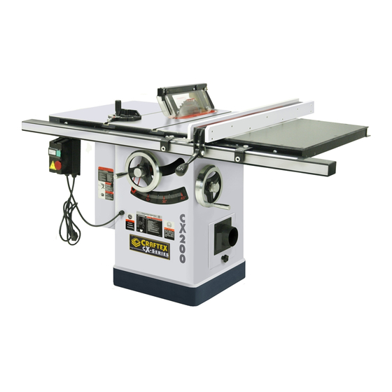
CX200/CX201 – Heavy Duty Table Saw Physical Features Blade Miter Fence Guard Gauge Extension Table Front Fence Rail Rear Fence Rail Blade Tilt Hand Wheel Blade Height Extension Hand Wheel Blade Tilt Table Lock Blade Height Lock Legs ON / OFF... -
Page 8: Setup
G. Magnetic Switch....... 1 begin assembly. Use a solvent cleaner that will not damage painted surfaces. WARNING CX200/CX201 is a very heavy machine, do not over-exert yourself. For safe moving method use fork truck or get the help of an assistant or friend. - Page 9 Figure-3 Inventory LIST OF CONTENTS S. Extension Wing (CX201) ....1 T. Legs (CX201) ........2 U. Foot Pads........2 V. Extension Wing (CX200) ....1 Figure-4 Minimum working space CX200 & CX201...
-
Page 10: Proper Grounding
50-feet in length and the cord is 14-gauge to prevent motor damage. Your CX200/CX201 should be wired with a plug having 3-prongs to fit a 3 prong grounding receptacle as shown in figure-5. Do not remove the grounding prong to fit it into a 2-pronged outlet. -
Page 11: Assembly
ASSEMBLY To assemble your CX200/201, read and Install the blade tilt hand wheel onto the understand the text and figures given. hand wheel shaft and secure it using set screw provided. See figure-8. Take the magnetic switch out of the saw cabinet and loosen the bolt securing the shipping brace, and remove the brace. - Page 12 Attach the dust port to the saw and secure Place a straight-edge on the main table and it using the knob as shown in figure-10. the extension wing, and make sure they are flat with each other. If the mating surface of the extension wing tilts down, use a masking tape along the bottom edge of the main table to shim the extension wing up.
-
Page 13: Cx200 Extension Table
See figure-14. Figure-16 Installing rear fence rail Figure-14 Installing front fence rail CX200 EXTENSION TABLE Now, install the fence rail tube onto the Install the extension table between the front front rail using cap screws, washers and flat and rear fence rails, securing it to the rails washers provided. -
Page 14: Cx201 Extension Table
Place a straight-edge across the extension CX201 EXTENSION TABLE wings and the extension table and level the Get an assistant to hold the extension table extension table by adjusting the feet, so between the front and rear fence rails. that the extension is flush with the Secure the extension table to the rails using extension wings and the main table. -
Page 15: Installing The Saw Blade
pointer window and re-install it on the right INSTALLING THE SAW BLADE side of the fence. Remove the screw securing the table insert to the table and remove the table insert. Raise the arbor all the way up using the blade height hand wheel located on the front of the saw and set the blade to 0- degree. -
Page 16: Blade Guard Installation
COLLECTOR Install the table insert and slide the knurled knob out, rotating it forward so that it CX200/CX201 features a 4” diameter dust engages the upper bracket. port to connect to a dust collector. When connecting to a dust collector, use a proper sized hose and make sure all the connections are sealed tightly. -
Page 17: Basic Controls
Magnetic Switch manual and you are familiar with the The magnetic switch on your CX200/CX201 functions and safety features on this has a green button to turn the machine machine. Failure to do so may cause “ON”... -
Page 18: Blade Guard
BLADE GUARD RIVING KNIFE blade guard assembly your The riving knife is a metal plate which CX200/CX201 consists clear prevents the newly cut work-piece from polycarbonate shield, spreader and anti- pinching at the backside of the blade and kickback pawls. -
Page 19: Work-Piece Inspection
WORK-PIECE INSPECTION OPERATIONS Before cutting the work-piece, make sure to Before doing the operation, make sure all inspect it for nails, staples, small pieces of the parts of the machine are assembled stone or metal and any other object which properly and you have done the test run. -
Page 20: Ripping
Since the blade guard can not be used reach the full speed and feed the work- when doing non-through cuts, there is great piece through the blade using a push stick, possibility of kickback. Make sure to have until the work-piece completely passes the the riving knife installed, when using saw blade. -
Page 21: Miter Cuts
Figure-34 Marking the angle of cut BEVEL CUTS The CX200/CX201 blade can be tilted to the left between 0° and 45° by rotating the blade tilt hand wheel. This feature of the saw allows making bevel cuts. -
Page 22: Adjustments
PARALLELISM power source. Your CX200/CX201 will give a better result Loosen the four mounting bolts (shown in if the main table is parallel to the blade. If it figure-36) securing the table on the cabinet... -
Page 23: Tensioning The V-Belt
To adjust the alignment: Turn “OFF” the table saw and remove the cord from the power source. Remove the table insert and loosen the two cap screws on the mounting block and adjust screws move spreader/riving knife. The set screws are to control the top, side (left &... -
Page 24: Replacing The V-Belts
REPLACING THE V-BELTS Turn the table saw switch “OFF” and remove the cord from the power source. Lower the blade to the maximum and open the motor cabinet. Loosen the hex nuts securing the motor as shown in figure-39 and move the motor up and remove the V- belts off the pulleys. -
Page 25: Parts Breakdown & List
CX200 / CX201 BODY PARTS BREAKDOWN... - Page 26 CX200 / CX201 BODY PARTS LIST REF# DESCRIPTION REF# DESCRIPTION CABINET HEX BOLT M10-1.5×20 CAP SCREW M10-1.25×25 FLAT WASHER 10MM LOCK WASHER 10MM LOCK WASHER 10MM FLAT WASHER 10MM HEX NUT M10-1.5 ANGLE SCALE DUST CLIP STRAIN RELIEF 46-1 UPPER BRUSH...
- Page 27 CX200 / CX201 TRUNION ASSEMBLY PARTS BREAKDOWN...
- Page 28 CX200 / CX201 TRUNION ASSEMBLY PARTS LIST REF# DESCRIPTION 134-4 R CAP ACITOR COVER 134-5 S CAP 200M 250V 1-1/4×2-3/4 HAND WHEEL LOCK 134-6 S CAP ACITOR COVER HAND WHEEL HANDLE 134-7 WIRING JUNCTION BOX 102-1 HAND WHEEL ORIENTATION PIN SET SCREW M5-.8×12...
- Page 29 KEY 5×5×30 LOCK WASHER 4MM BALL BEARING 6005 2Z SET SCREW M4-.7×12 COLLAR BLADE ARBOR TRUNNION ARBOR PULLEY COLLAR BLADE ARBOR FLANGE RING PHLP HD SCR M5-.8×12 LOCK WASHER 5MM FLAT WASHER 5MM LOCK NUT M16-1.5 LEFT BRACKET RIGHT BRACKET CAP SCREW M8-1.25×30 FLAT WASHER 8MM LOCK WASHER 8MM...
- Page 30 CX200 / CX201 BLADE GAURD PARTS BREAKDOWN...
- Page 31 CX200 / CX201 BLADE GAURD PARTS LIST REF# DESCRIPTION REF# DESCRIPTION ELASTIC PIN HEX HEAD BOLT SPRING GUARD SUPPORT LOCK NUT PAN HEAD SCREW SUPPORTING ARM SPACER PAN HEAD SCREW SPACER FLAT WASHER PAN HEAD SCREW TOP GUARD FLAT WASHER...
- Page 32 CX200 / CX201 MITER GAUGE PARTS BREAKDOWN & PARTS LIST REF# DESCRIPTION REF# DESCRIPTION MITER STOP PIN BLOCK MITER BAR COMPRESSION SPRING MITER STOP PIN SET SCREW M4-.7*6 CAP SCREW M4-.7*14 CAP SCREW M4-.7*14 POINTER MITER GUAGE MITER RING FLAT WASHER 4MM FLAT HD SCR M5-.8*8...
- Page 33 CX200 / CX201 FENCE PARTS LIST REF# DESCRIPTION REF# DESCRIPTION FANCE FACE HEX BOLT M6-1*40 CAP SCREW M6-1*16 LOCK NUT M6-1 GLIDE PAD HEX BOLT M10-1.5*45 FENCE SCALE WINDOW LOCK NUT M10-1.25 SET SCREW M12-1.75*15 CAM FOOT PHLP HD SCR M5-.8*10...
- Page 34 CX200 – 30” RAILS & EXTENSION TABLE PARTS BREAKDOWN...
- Page 35 CX200 – 30” RAILS & EXTENSION TABLE PARTS LIST REF# DESCRIPTION REF# DESCRIPTION INSERT FENCE LOCK WASHER 8MM GUIDE TUBE FLAT WASHER 8MM SCALE REAR RAIL FRONT RAIL HEX BOLT M8-1.25*40 CAP SCREW M6-1*16 HEX NUT M8-1.25 LOCK WASHER 6MM...
- Page 36 CX201 – 50” RAILS & EXTENSION TABLE PARTS BREAKDOWN...
- Page 37 CX201 – 50” RAILS & EXTENSION TABLE PARTS BREAKDOWN REF# DESCRIPTION REF# DESCRIPTION INSERT FENCE CAP SCREW M6-1*16 FOOT LOCK WASHER 6MM HEX BOLT M8-1.25×60 FLAT WASHER 6MM CAP SCREW M6-1*16 HEX BOLT 5/16-18*1-1/2 CAP SCREW M8-1.25*20 LOCK WASHER 8MM HEX BOLT M8-1.25*30 FLAT WASHER 8MM GUIDE TUBE...
-
Page 38: Warranty
This warranty shall not apply to consumable products such as blades, bits, belts, cutters, chisels, punches etceteras. Craftex shall in no event be liable for injuries, accidental or otherwise, death to persons or damage to property or for incidental contingent, special or consequential damages arising from the use of our products.
Need help?
Do you have a question about the CX200 and is the answer not in the manual?
Questions and answers
Is there available a splitter like part number 350 that is made for narrow kerf saw blades? The saw I have is CX201 and has a splitter on that is not mounted to the guard assembly and works well with wider blades but not narrow kerf blades.
The document does not mention a specific splitter for narrow kerf saw blades for the Craftex CX200. It lists a splitter (part #350) and a riving knife (part #351), but it does not specify if these are compatible with narrow kerf blades.
This answer is automatically generated