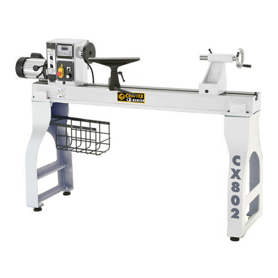
Craftex CX Series User Manual

Craftex CX Series User Manual

18” x 47” heavy duty wood lathe
Hide thumbs Also See for CX Series:

Advertisement

Quick Links

CX802
18" X 47" HEAVY DUTY WOOD LATHE
User Manual
Version 2

Advertisement

Table of Contents
loading

Summary of Contents for Craftex CX Series

  • Page 1 CX802 18” X 47” HEAVY DUTY WOOD LATHE User Manual Version 2...
  • Page 2: Table Of Contents

    TABLE OF CONTENTS General Safety Instructions for Machines ............... 3 Specific Safety Instructions ..................4 CX802 Features...................... 5 Physical Features ....................6 Proper Grounding ....................7 Un-Packing ......................8 Setup ........................8 Mounting ......................... 8 Assembly ........................ 9 Basic Controls......................10 Test Run .........................
  • Page 3: General Safety Instructions For Machines

    GENERAL SAFETY INSTRUCTIONS FOR MACHINES Extreme caution should be used when operating all power tools. Know your power tool, be familiar with its operation, read through the owner’s manual, and practice safe usage procedures at all times. ALWAYS read and understand the NEVER leave a tool unattended while it user manual before operating the is in operation.
  • Page 4: Specific Safety Instructions

    CX802 – HEADY DUTY WOOD LATHE SPECIFIC SAFETY INSTRUCTIONS Like all power tools and machinery, proper safety and attention must be adhered to. There is danger associated with using any tool or machine so pay careful attention each and every time you use your tool. If you are not familiar with the operations of a lathe, you should obtain the advice and/or instructions from a qualified professional.
  • Page 5: Cx802 Features

    MODEL CX802 – 18" x 47" HEAVY DUTY WOOD LATHE As part of the growing line of Craftex CX-Series woodworking equipment, we are proud to offer the CX802, a 18" x 47" Heavy Duty Wood Lathe. By following the instructions and procedures laid out in this user manual, you will receive years of excellent service and satisfaction.
  • Page 6: Physical Features

    CX802 – HEAVY DUTY WOOD LATHE PHYSICAL FEATURES...
  • Page 7: Proper Grounding

    PROPER GROUNDING Grounding provides path least resistance for electric current to reduce the WARNING! risk of electric shock. Improper connection of the equipment- grounding conductor can result in a risk CX802 is equipped with a 220-V 3 phase of electric shock. Check with a qualified motor and is provided with a power supply electrician if you are in doubt as to cord that is to be connected directly to the...
  • Page 8: Unpacking

    UNPACKING SETUP The machine is properly packaged and Before setting up your machine, you should shipped complete in a crate for safe read and understand the instructions given transportation. When unpacking, carefully in this manual. inspect the crate to ensure that nothing has been damaged during transit.
  • Page 9: Assembly

    Remove the support block and place it ASSEMBLY under the other stand leg and install the other rubber feet in the same way. TO ASSEMBLE YOUR CX802: Remove the support block and position the Position the stand legs up right, aligned lathe on the floor.
  • Page 10: Basic Controls

    BASIC CONTROLS TEST RUN The basic controls on your CX802 are Once you have assembled your lathe shown in figure-6. Make sure to familiar completely, it is then time for a test run to yourself with these controls before turning make sure that the machine works properly your lathe ON.
  • Page 11: Headstock Adjustment

    6. Without opening the emergency stop HEADSTOCK button , turn the spindle forward/reverse ADJUSTMENT switch to the "L" or "R" position. The machine should not start at either The headstock on the CX802 features a position. cam-action lever clamping system allows securing it to the bed.
  • Page 12: Tailstock Adjustment

    TAlLSTOCK ADJUSTMENT TOOL REST ADJUSTMENT The tool rest on CX802 features a cam- You can adjust the tailstock in the same action lever clamping system which allows manner as the headstock. securing the tool rest base onto the lathe bed. TO POSITION THE TAILSTOCK ALONG THE LATHE BED: TO POSITION THE TOOL REST...
  • Page 13: Installing/Removing Head Stock Center

    To adjust the angle and height of the tool TO REMOVE THE CENTER: rest: Make sure the switch is in the OFF position Loosen the lock handle securing the tool the cord is disconnected from the power rest to the base and adjust the tool rest outlet.
  • Page 14: Installing/Removing Faceplate

    Insert the tapered end of the center into the TO INSTALL THE FACEPLATE: quill and push it in, making sure that it is installed securely into the quill. See figure- Make sure the switch is in the OFF position the cord is disconnected from the power outlet.
  • Page 15: Spindle Speeds

    TO REMOVE THE FACEPLATE: The high speed range is used when a smooth finish is required and when only Make sure the spindle lock pin is engaged. light cuts are made. Loosen the screws securing the faceplate to the spindle and unthread the faceplate. The mid range is a compromise between the high and low range.
  • Page 16: Workpiece Inspection

    Lift the motor assembly all the way up, SPINDLE TURNING using belt tensioning handle shown in figure-16, and retighten the belt tension lock The turning operation in which the work- lever to lock the motor in position. piece is mounted between the headstock and the tailstock is called spindle turning.
  • Page 17: Faceplate Turning

    center into the work-piece about 1/4" and MAINTENANCE re-tighten the quill lock lever. During the life of your machine, you will need Position the tool rest approximately 1/8” to practice some regular maintenance to above the work-piece center and 1/4" away keep your lathe...
  • Page 18: Belt Replacement

    Remove the belt from the lower (motor) BELT REPLACEMENT pulleys first, then from the upper (spindle) pulleys. TO CHANGE THE BELT: Make sure the switch is in the OFF position TO INSTALL THE NEW BELT: and the cord is disconnected from the power source.
  • Page 19: Wiring Diagram

    CX802 WIRING DIAGRAM...
  • Page 20: Troubleshooting

    CX802 TROUBLESHOOTING PROBLEM POSSIBLE CAUSE SOLUTION 1. Work piece warped, out of 1. Correct problem by planing, round, has major flaw, or was sawing, or scrap work-piece improperly prepared for turning all together 2. Worn spindle bearings 2. Replace bearings Excessive Vibration.
  • Page 21: Parts Breakdown

    CX802 STAND AND BED PARTS BREAKDOWN...
  • Page 22 CX802 HEADSTOCK PARTS BREAKDOWN...
  • Page 23: Parts List

    CX802 PARTS LIST DESCRIPTION DESCRIPTION 1 V2 STAND LEG PLATE KEY 6X6X48 FOOT CAP SCREW M10x30 BAFFLE HANDLE CAP SCREW M10x35 WASHER 10 C-RING C-19 MOTOR ASSEMBLY PLATE SET SCREW M5x10 SET SCREW M6X12 BAFFLE MOTOR PULLEY 11 V2 TOOL REST BASE NUT M12X1 12 V2 TOOL REST...
  • Page 24: Warranty

    This warranty shall not apply to consumable products such as blades, bits, belts, cutters, chisels, punches etceteras. Craftex shall in no event be liable for injuries, accidental or otherwise, death to persons or damage to property or for incidental contingent, special or consequential damages arising from the use of our products.

This manual is also suitable for:

Cx802

Table of Contents