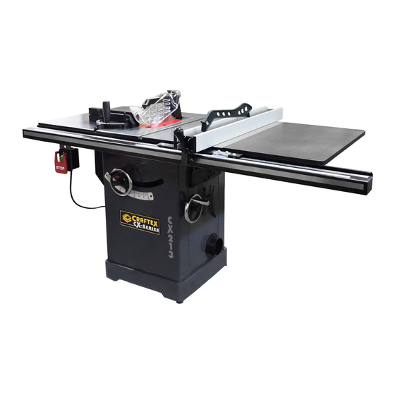
Craftex CX Series User Manual

Craftex CX Series User Manual

10" cabinet table saw
Hide thumbs Also See for CX Series:

Advertisement

MODEL CX213 & CX214
10" CABINET TABLE SAW
USER MANUAL

Advertisement

Table of Contents
loading

Summary of Contents for Craftex CX Series

  • Page 1 MODEL CX213 & CX214 10” CABINET TABLE SAW USER MANUAL...
  • Page 2: Table Of Contents

    TABLE OF CONTENTS General Safety Instructions.................. 3 Specific Safety Instructions .................. 4 Features....................... 5 CX213 & CX214 Cabinet Saw ................6 Grounding Instruction................... 7 Extension Cords....................8 Integrated Mobile Base and Machine Leveling ............ 8 Unpacking ......................9 Table Saw Placement...................10 Mounting Fence Storage Brackets ..............11 Rear Rail Installation ....................12 CX214 Extension Table and Rail Installation............12...
  • Page 5: Features

    FEATURES MODEL CX213 & CX214 – 10” CABINET TABLE SAW As part of the growing line of Craftex woodworking equipment, we are proud to offer CX213 and CX214 10” Cabinet Table Saw. By following the instructions and procedures laid out in this owner’s manual, you will receive years of excellent service and satisfaction.
  • Page 6: Cx213 &Cx214 Cabinet Saw

    CX213 &CX214 Cabinet Saw Thank you for Choosing the CX213 or the overall depth of cut. This cabinet CX214 for your Cabinet Saw. This unit saw is also equipped with a rail mounted has been tested and inspected before fence that slides effortlessly towards or shipment insure optimum...
  • Page 7: Grounding Instruction

    The supplied push stick is used to help NOTE: support the work piece as it passes by Please note that the riving knife will the saw blade while keep your hands need to be removed in certain instances safe and away from the blade helping to when you are not cutting through the reduce the risk of injury while performing work piece entirely.
  • Page 8: Extension Cords

    Extension Cords: NOTE: If the thermal overload protection kicks If you must use an extension cord in you must allow the motor to cool makes sure that it is of the right size and down sufficiently before resetting the in good condition. When using an circuit by pushing the reset button extension cord you must use one heavy located above the on/off switch for the...
  • Page 9: Unpacking

    instructions for the proper breakers and circuit size. When in doubt always consult an electrician.  Low voltage. Although the motor is designed for operation on the voltage and frequency specified on the motor, which isn’t a problem for normal loads 10 percent above or below that figure.
  • Page 10 to remove built up difficult packing grease. To prevent rust or oxidation of your machines surface apply a light coating of wax or use regular applications of aftermarket rust inhibitors. Figure 3 Table Saw Assembly WARNING!!! Always wear the appropriate personal protective equipment during the entire setup and assembly process.
  • Page 11: Mounting Fence Storage Brackets

    NOTE: Be sure that the table extension wings are flush with the front edge. Front Rail Installation Mounting Fence Storage Brackets 1.)Loosely thread the 3 square head bolts into the front of the table saw as The miter gauge and blade guard seen in figure 7 below.
  • Page 12: Rear Rail Installation

    Figure 9 4.)Now tighten down the nuts holding the square head bolts into place to firmly Figure 11 secure the rail to the table. 2.) Install the leveling feet with an M8 hex nut A into the bottom of the extension table support leg as seen Rear Rail Installation below in figure12.
  • Page 13 Figure 14 Figure 13 4.) Give the spreader a tug to insure that it is securely locked into place. Blade Guard Installation 5.) Lift the blade guard cover just high enough so that you can slide the The blade guard assembly is made up table insert in to place over the of clear two polycarbonate split shields blade.
  • Page 14: Anti Kickback Pawls & Riving Knife

    dado blade. The riving knife can also be used for cutting operations where the blade guard or its components may get in the way of safe operation like on very narrow cuts for example. main difference between spreader and the riving knife is that the riving knife mounts below the blades highest point of rotation.
  • Page 15 5.) Turn on the table saw. WARNING!!! In order to function properly the riving 6.) Set the blade on a 45° then slowly knife must not be bent or out of raise the blade to its maximum alignment with the blade. Should the height.
  • Page 16: Fence Assembly

    2.) Loosen the locking knob on the zero WARNING!!! clearance insert. Now remove the Always disconnect machine from its insert, blade guard assembly, and power source when installing riving knife. removing saw blades to prevent any accidental starting machine 3.) Find a corner cut on the arbor and resulting in property damage or serious push the red bar into the corner of personal injury.
  • Page 17: Aligning And Leveling The Rip Fence

    Note: The rip fence should be no higher than 2mm above the table surface to prevent thin pieces of material possibly getting jammed or stuck under the fence during cutting operations resulting in property damage or even serious personal injury. How To Level and Adjust the Height of The Fence: 1.) Loosen the hex nut F on the leveling...
  • Page 18: Adjusting The Rip Fence Pointer

    Dust Collection Hook Up There is a 4” dust collection port located at the back of your CX213 and CX214 allowing your machine to be connected to a dust collector. (dust collector in not included) How to Connect to a Dust Collector: 1.) Fit 4”...
  • Page 19: Miter Gauge And Storage Box

    To maintain control of larger work pieces start of by feeding the material by hand and once the material is fully supported by on the table saw surface use the push stick to complete the cut so that your hands don’t pass directly by the blade.
  • Page 20: Periodic Maintenance

    Periodic Maintenance WARNING!!! Always wear safety glasses, respirator  Check the magnetic starter switch and hearing protection when operating before each use. If the switch is machinery. damaged in any way DO NOT OPERATE IT, replace it immediately. Cleaning & Lubrication ...
  • Page 21 blade, keeping the square flat against the table and flat part of the blade. DO NOT touch the teeth or the table insert with the square. If the blade is at the correct angle at 90 degrees, remove the motor cover (G) Figure 32 figure 34 then loosen the hex nut (C) To access the dust hood, remove the...
  • Page 22: Bevel Angle Pointer/Bade Height Adjustment

    Deg. stop screw (F), figure 36 under the manually align the pointer with table using a hex wrench. Then turn the zero on the bevel scale. Re- hand wheel until the blade is at 45 Deg. tighten the screw and re-attach to the table surface.
  • Page 23 1. Loosen the blade height lock The blade can be tilted to the left anywhere from 0 Deg. (90 Deg. to knob (B) by turning counter the table) to 45 Deg. Turn the hand clockwise. wheel to the left or right as required to set the blade to the desired angle.
  • Page 24: Belt Replacement

    4. Remove the dust hood (Philips screwdriver needed) and the fixing plate, (5mm Hex Key required). Figure 43 Figure 45 7. Tighten the Hex Cap Screw (E), Figure 44 re-install the dust hood, Figure 43 fixing plate motor cover, ensuring all fasteners are tight. 5.
  • Page 25: Ripping

    pushing it into the blade and firmly against the fence simultaneously for a straight cut.  Never rip or cut wood without using the fence or miter gauge, this will help to avoid kickback.  Always use the blade guard and splitter assembly when cutting wood.
  • Page 26 through the blade. Push sticks with non slip grippers are readily WARNING!!! available products but a shop When a rip cut is completed, shut down made push stick work just as the saw and wait for the blade to come well.
  • Page 34 Part No. Part No. Descriptions Specification RIP FENCE ASSEMBLY Rip Fence 924774-000 PCX213001RF Assembly PCX2130011R .1 250483-615 End Cap PCX2130012R .2 310541-909 Adaptor PCX2130013R .3 000002-308 Hex. screw M6*1.0P*45 PCX2130014R .4 171993-904 Bracket PCX2130015R .5 250602-621 Frictional Plate PCX2130016R .6 048701-101 Square Bolt M8*1.25P*20 PCX2130017R...
  • Page 35 PCX21300113 M8*1.25P(13B .13 008006-100 Hex Nut *6.5H) PCX21300114 .14 006001-049 Flat Washer 8.5*16*2.0t PCX21300115 .15 250472-621 Plastic Set Screw M12*1.75P PCX21300116 .16 000004-306 Hex. screw M10*1.5P*50 PCX21300117 .17 230282-615 Ball PCX21300118 Compress Cam .18 922141-000 Assembly PCX2130019R .19 250471-621 Frictional Plate PCX21300120 .20 002103-103 Flat Head Screw...
  • Page 36 PCX21300133 .33 000302-101 Pan Head Screw M4*0.7P*6 BLADE GUARD ASSEMBLY 924573-000 PCX213002BG Blade Guard Assy .1 251246-000 PCX2130021BG Right Cover .2 290073-905 PCX2130022BG Shoulder Shaft .3 251247-000 PCX2130023BG Left Cover .4 043317-000 PCX2130024BG O-Ring P006 .5 130365-903 PCX2130025BG Clamper Support PCX2130026BG M5*0.8P(8B*6 .6 008302-100...
  • Page 37 PCX21300217B .17 360864-000 PCX21300218B .18 360865-901 Spreader Shaft PCX21300219B .19 280160-901 Spring PCX21300220B .20 010204-000 Retaining Ring ETW-7 PCX21300221B .21 280163-901 Spring PCX21300222B Anti-Kick Finger - .22 171379-904 Right PCX21300223B .23 000303-110 Pan Head Screw M5*0.8P*30 PCX21300224B .24 174397-904 Spreader PCX21300225B .25 575104-000 Warning Label...
  • Page 38 .6 230408-000 PCX2130036MG Universal Handle .7 360355-901 PCX2130037MG .8 000204-114 PCX2130038MG SET Screw M8*1.25P*6 .9 381390-904 PCX2130039MG Slot Bar PCX21300310M .10 130380-903 Packing PCX21300311M Flat Head Phillip .11 000403-209 M6*1.0P*8 Screw PCX21300312M .12 000303-202 Pan Head Screw M5*0.8P*8 PCX21300313M .13 006002-009 Flat Washer 5.2*10*1.0t PCX21300314M...
  • Page 39 TABLE SAW ASSEMBLY 051386-000 PCX213004 Extension Table PCX213006 Table Insert 924397-000 Assembly 051368-000 PCX213007 Table 006001-049 PCX213008 Flat Washer 8.5*16*2.0t 000003-104 PCX213009 Hex. screw M8*1.25P*20 051370-000 PCX213010 Up-down Bracket PCX213011 M8*1.25P(13B 008006-100 Hex Nut *6.5H) 280258-905 PCX213012 Spring 000104-106 PCX213013 Cap Screw M8*1.25P*20 PCX213014...
  • Page 40 174396-904 PCX213027 Riving Knife 001902-110 PCX213028 SET Lock screw M6*1.0P*8 000804-106 PCX213029 Round Head Screw M5*0.8P*16 361251-905 PCX213030 361250-901 PCX213031 Fixing Knob 110071-000 PCX213032 Lock Handle 390017-000 PCX213033 Saw blade 10''*40T 174399-901 PCX213034 Saw blade clamp 380205-901 PCX213035 TW5/8"-12 PCX213037 Round Head 002503-101 M5*0.8P*12...
  • Page 41 014354-000 PCX213058 Poly V-Belt 135J7 381281-902 PCX213059 Arbor 000002-103 PCX213060 Hex. screw M6*1.0P*16 006001-020 PCX213061 Flat Washer 6.2*20*3.0t 006007-114 PCX213062 Flat Washer 6.4*16*1.6t 361245-901 PCX213063 Lead Screw 010007-000 PCX213064 Retaining Ring STW-16 012002-003 PCX213065 4*4*8 174324-000 PCX213066 Washer 031011-001 PCX213067 Bearing 51100 090324-000...
  • Page 42 920703-000 PCX213085 Fixing Knob 090326-000 PCX213086 Worm Gear Box 320395-901 PCX213087 Worm Shaft 030106-001 PCX213088 Ball Bearing 6201 010102-000 PCX213089 Retaining Ring RTW-32 130361-000 PCX213090 Gear 006001-127 PCX213091 Flat Washer 5.5*22*2.0t 000001-109 PCX213092 Hex. screw M5*0.8P*12 000104-113 PCX213093 Cap Screw M8*1.25P*45 320394-901 PCX213094...
  • Page 43 18NC*3/4" 000003-316 PCX213114 Hex. screw M8*1.25P*60 250399-615 PCX213115 Wheel 006001-022 PCX213116 Flat Washer 6.3*13*1.0t 230041-000 PCX213117 Leveling foot 170541-904 PCX213118 Slide Shelf PCX213119 Hex Screw M8*1.25P*16/( 049201-101 w/Washer 13B*6.5H) 251251-615 PCX213120 Storage Box PCX213121 Round Head Screw M6*1.0P*10/6* 001603-102 w/Washer 13.2*1.0t 170965-904 PCX213122...
  • Page 44 PCX2131246M 006501-100 Tooth Washer 4.3*8.5(BW-4) PCX2131247M 020003-000 Strain Relief SB7R-3 PCX2131242M Magnetic Switch 3HP*220V- 124.2 937882-000 Assy 240V*1PH PCX213125MS SJT14AWG*3 453012-023 Power Cord C*2550mm 36” RAIL + RIGHT TABLE ASSEMBLY PCX213127RR 36" Rail + Right 924901-000 36" Table Assembly PCX2131279R .9 000704-102 Flat Head Screw M8*1.25P*25...
  • Page 45 Assembly PCX2130014 .4 924904-000 Rail Brace 36" RIGHT TABLE ASSEMBLY PCX213002T Right Table 924773-000 Assembly .1 440098-000 PCX2130021T PDF Table .2 173139-902 PCX2130022T Brace .3 230086-901 PCX2130023T Self-Tapping screw PCX213127T 52" Rail + Right 924878-000 52” Table Assembly 52” RAIL ASSEMBLY 924879-000 PCX213001R 52"...
  • Page 46 Assembly PCX2130014 .4 924881-000 Rail Brace 52" RIGHT TABLE ASSEMBLY PCX213002RT Right Table 924809-000 Assembly PCX2130021RT CAP Screw w/ M8*1.25P*20/8 001803-102 Spring Washer .2*15.4 .2 006001-049 PCX2130022RT Flat Washer 8.5*16*2.0t PCX2130023RT M8*1.25P(13B 008006-100 Hex Nut *6.5H) .4 000704-102 PCX2130024RT Flat Head Screw M8*1.25P*25 .5 230041-000 PCX2130025RT Leveling foot...
  • Page 47 w/Washer 13B*6.5H) 130368-903 PCX213154 Adjusting Bushing 001901-101 PCX213155 Set screw M5*0.8P*5 010001-000 PCX213159 Retaining Ring STW-10 043322-000 PCX213160 O-Ring PCX213161 Round Head Lock M5*0.8P*10 全 002402-102 Screw w/Washer 牙-5*16*1.5t 011001-103 PCX213162 Spring Pin 3*10 174398-904 PCX213166 Hook 251243-615 PCX213167 Knob 006701-100 PCX213168 Wave Washer...
  • Page 48: Warranty

    This warranty shall not apply to consumable products such as blades, bits, belts, cutters, chisels, punches etceteras. Craftex shall in no event be liable for injuries, accidental or otherwise, death to persons or damage to property or for incidental contingent, special or consequential damages arising from the use of our products.

This manual is also suitable for:

Cx213Cx214

Table of Contents