Table of Contents
Advertisement
Advertisement
Table of Contents

Related Manuals for EMAK K 700 H


Summary of Contents for EMAK K 700 H
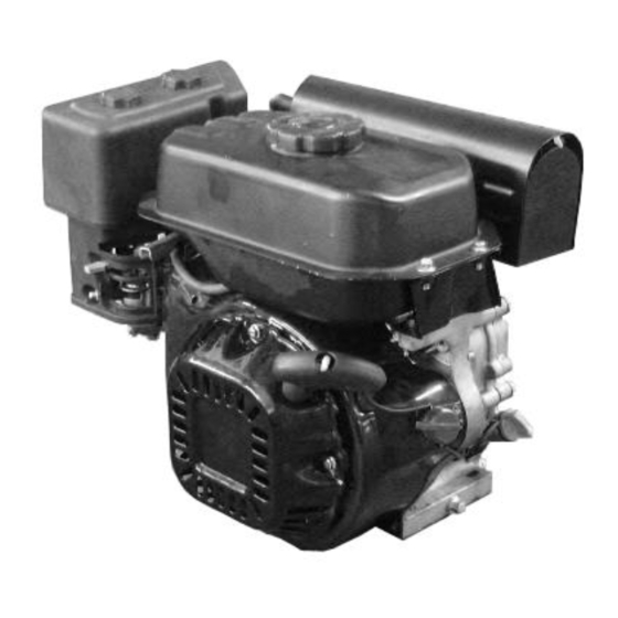
- Page 1 WORKSHOP MANUAL Engine: K 700 H – K 800 H (183 cc)
- Page 2 Workshop manual SAFETY PRECAUTIONS Thoroughly read this MANUAL before operating and servicing the generator set. Safe operation and top performance can only be attained when equipment is operated and maintained properly. The following symbols, found throughout this manual, alert you to potentially dangerous conditions to operators, service personnel and equipment.
-
Page 3: Table Of Contents
Workshop manual 1. Parameters ..........................4 Engine Structure ........................... 4 Product Technical Parameters ...................... 6 Drawings of Mounting Dimensions ....................7 Drawings of PTO Dimensions ....................... 8 Diagram of Electrical Wiring ......................10 2. Service information ........................ 12 Precautions for Maintenance ....................... 12 Serial number location ......................... -
Page 4: Parameters
Workshop manual Parameters Engine Structure THROTTLE LEVER CHOKE LEVER FUEL COCK ENGINE SWITCH OIL DRAIN PLUG STARTER GRIP RECOIL STARTER Fuel cock: a switch in the fuel line to control the fuel flow in the fuel line. Recoil starter: serves to start the engine closes the choke before engine’s cold starting, and the carburetor will deliver a very rich Choke lever: mixture to let the engine be easily startable. - Page 5 Workshop manual FUEL FILLER CAP FUEL TANK MUFFLER AIR CLEANER SPARK PLUG OIL DRAIN PLUG Air cleaner: protects the engine through removing dust and other impurities in the air. delivers the high voltage of the ignition coil into the engine’s combustion chamber, and Spark plug: produces sparks by electric discharge between electrodes, to ignite the fuel-air mixture.
-
Page 6: Product Technical Parameters
Workshop manual Product Technical Parameters K700H – K800H Model Type Single cylinder, 4-Stroke, Forced Air Cooling, OHV 25° Displacement (cc) 183 cc Cylinder bore × Stroke (mm) 65×55 Net power (KW / 3600 rpm) Net torque (Nm / rpm) 10.8 / 2500 Idle speed (rpm) 1800 ±150 Compression ratio... -
Page 7: Drawings Of Mounting Dimensions
Workshop manual Drawings of Mounting Dimensions... -
Page 8: Drawings Of Pto Dimensions
Workshop manual Drawings of PTO Dimensions Type A Type C Type R Type D... - Page 9 Workshop manual Type E Type S Type U Type A22...
-
Page 10: Diagram Of Electrical Wiring
Workshop manual Diagram of Electrical Wiring... - Page 11 Workshop manual Engine Type with Oil Alert and Without Electric Starting...
-
Page 12: Service Information
Workshop manual Service information 2.1 Precautions for Maintenance 1. Parts, oil and grease must be genuine Efco and 5. Clean parts cleaning solvent upon Oleo-mac products or products designated by disassembly. Lubricate any sliding surfaces Efco and Oleo-mac. Parts not meeting Efco and before reassembly. -
Page 13: Serial Number Location
Workshop manual Follow the instructions represented by these symbols when maintaining: : Used oil : Used special tool : Used grease ○×○ (○):Indicates flange bolt model, length and quantity. P. :Indicates pages 2.2 Serial number location The serial number is stamped on the crankcase, as shown on the following drawing when inquiring about engine or ordering parts in order to get correct parts for the unit being serviced by Efco or Oleo-Mac. -
Page 14: Maintenance Standards
Workshop manual 2.3 Maintenance standards Standard Service limit Part Item K700H – K800H K700H – K800H - Engine Compression pressure (kg/cm 6.5 ~ 8.5 Cylinder Cylinder bore 65.165 Skirt outside diameter 64.985 64.845 0.015 ~ 0.005 Piston-to-cylinder clearance 0.12 Piston 17.002 ~... -
Page 15: Fastener Torque Specification
Workshop manual 2.4 Fastener Torque Specification (1) Torque specification Item Thread specification Torque range (Nm) Connecting rod bolt M7x1 13 ~ 15 Cylinder head bolt M8×1.25 32 ~ 35 Flywheel mounting nut M14×1.5 80 ~ 90 Crankcase cover bolt M8×1.25 27 ~ 30 Oil drain bolt (in crankcase) M10×1.25... -
Page 16: Maintenance
Workshop manual Maintenance 3.1 Maintenance schedule First Every 3 Every 6 Every Each month months months year or Maintenance schedule or 20 or 50 or 100 hours hours hours hours ● Check level Engine oil ● ● Replace ● Check ●... -
Page 17: Engine Oil
In order to obtain the best performance of the engine, it is recommended to use special engine oil certified to be OK for Emak engines. SAE 10W-30 is the recommended oil. Other viscosities shown in the chart may be used when the average temperature in your area is within the recommended range. -
Page 18: Air Cleaner
Workshop manual 3.3 Air cleaner A dirty air filter will restrict fair flow to the carburetor, reducing engine performance. If the engine is operated in dusty areas, clean the air cleaner more often than specified in the MAINTENANCE SCHEDULE Warning Washing filter element with gasoline or flammable solvents many cause fire or explosion, please use soapy water or nonflammable solvent. -
Page 19: Muffler
Workshop manual 3.4 Muffler Long use of the muffler can cause carbon deposit, which will severely affect the exhaust system; in order to let exhaust system work more reliably, we normally need to remove the carbon deposit from the muffler. Use a hand hammer to gently knock the muffler, and blow it with compressed air to remove the carbon deposit inside it. -
Page 20: Valve Clearance
Workshop manual 3.6 Valve clearance Valve clearance inspection and adjustment must be done with the engine cold. 1. Remove the cylinder head cover, and set the piston at top dead centre of the compression stroke (both valves will be fully closed). -
Page 21: Governor
Workshop manual 3.9 Governor 1) Take down the fuel tank. Governor arm Governor spring 2) Loosen the nut on the governor arm pinch bolt. pinch bolt 3) Move the arm until the throttle is completely open, and hold it in that position. 4) Rotate the governor arm shaft as far as it will go in same direction it was just moved by the governor arm, and then tighten the governor... -
Page 22: Troubleshooting
Workshop manual Troubleshooting 4.1 Hard Starting ENGINE FLOODED too much fuel (TRY AGAIN AFTER A FEW MINUTES) FUEL LEVEL too low (ADD FUEL INTO FUEL TANK) FUEL FILTER clogged (WASH FUEL FILTER) FUEL SYSTEM CARBURETOR faulty or out of adjustment (SEE 5-2-3) AIR CLEANER dirty (SEE 3-3) -
Page 23: Low Power
Workshop manual 4.2 Low Power FUEL QUALITY poor (ADD CLEAN FRESH FUEL OF DESIGNATED QUALITY INTO TANK) FUEL FILTER clogged (WASH FUEL FILTER) CARBURETOR faulty or out of adjustment (SEE 5-2-3) FUEL SYSTEM CHOKE not fully open (OPEN MAXIMALLY) AIR CLEANER dirty (SEE 3-3) SPARK PLUG faulty (SEE 3-5) -
Page 24: Speed Unstable
Workshop manual 4.3 Speed Unstable FUEL low / poor quality / contaminated (ADD CLEAN FRESH FUEL OF DESIGNATED QUALITY INTO TANK) FUEL FILTER clogged (WASH FUEL FILTER) FUEL SYSTEM CARBURETOR faulty or out of adjustment (SEE 5-2-3) SPARK PLUG faulty SPEED (SEE 3-5) IGNITION... -
Page 25: Engine Liable To Stall
Workshop manual 4.5 Engine Liable to Stall SPARK PLUG dirty and wet (SEE 3-5) CARBURETOR fuel level too high (ADJUST CARBURETOR FLOAT HEIGHT) ENGINE LIABLE TO STAL CARBURETOR IDLING out of adjustment (SEE 3-7) CARBURETOR insulation damaged (SEE 5-2-3) 4.6 Engine Liable to Stall SPARK PLUG dirty and wet (SEE 3-5) MUFFLER clogged... -
Page 26: Engine Overheating
Workshop manual 4.7 Engine overheating IGNITION time wrong (ADJUST IGNITION TIME) ENGINE OIL insufficient ordirty (ADD OR CHANGE OIL) MUFFLER OR EXHAUST PIPE clogged (SEE 3-4) PISTON RING faulty causing blow-by between cylinder and crankcase (REPLACE WORN PARTS) ENGINE OVERHEATING ENGINE speed too high (CHECK AND REPAIR GOVERNOR SYSTEM OR REPLACE GOVERNER GEAR) -
Page 27: Engine'sabnormal Sound
Workshop manual 4.8 Engine’s Abnormal Sound PISTON AND PISTON RINGS worn (REPLACE PISTON AND PISTON RINGS) CONNECTING ROD, PISTON PIN AND PISTON PIN BORE worn (REPLACE WORN PARTS) KNOCKING Piston pin-to-connecting rod clearance too big SOUND (REPLACE WORN PARTS) PISTON RING broken (REPLACE PISTON RING) COMBUSTION CHAMBER carbon deposit too much (REMOVE CARBON DEPOSIT) -
Page 28: Electric Starting System Failure
Workshop manual 4.9 Electric Starting System Failure Battery faulty (CHARGE OR REPLACE) WIRE OR CONNECTOR short-circuited or broken (REPLACE WORN PARTS) FUSE burn out (REPLACE) DOES PELAY ENGINE SWITCH faulty (SWITCH) HAS (REPAIR OR REPLACE) CLICKING SOUND? BATTERY VOLTAGE insufficient (CHARGE OR REPLACE) WIRE OR CONNECTOR short-circuited or broken (REPLACE WORN PARTS) -
Page 29: Cylinder Compression Check
Workshop manual 4.10 Cylinder Compression Check 1) Remove spark plug cap and spark plug. 2) Install a compression gauge in the spark plug hole. Compression 3) Install a compression gauge in the spark plug hole, crank the gauge engine several times with the recoil starter and measure cylinder compression Cylinder 6.0 ~... -
Page 30: Disassembly And Service
Workshop manual Disassembly and service 5.1 Precautions for Disassembly 5.1.1. Disassembly Be familiar with the machine’s structure and working principles before disassembly, it is the prerequisite of correct disassembly. Try best not to detach the parts that can avoid being detached. Aimless detaching not only increases work load of the repair, but also deteriorates the originally good fitting relation between parts and fitting accuracy, which leaves new hazards of failure. -
Page 31: Disassembly And Service Of Engine
Workshop manual 5.2 Disassembly and Service of Engine 5.2.1. Fuel tank Warning Fuel tank cap Drain the fuel tank and fuel Assembly: Make sure the vent hole tube fuel thoroughly out is clean and unclogged. before disassembling. Fuel Blow if necessary. vapor or spilled gasoline may ignite. -
Page 32: Air Cleaner, Muffler
Workshop manual 5.2.2. Air cleaner, Muffler Muffler Assembly: Install after removing the carbon deposits from the muffler by gently knocking with plastic hammer. Air cleaner cover Exhaust pipe gasket Air cleaner cover Air cleaner grid Air cleaner base Disassembly / Assembly: ... -
Page 33: Air Cleaner, Muffler
Workshop manual 5.2.3. Air cleaner, Muffler a Disassembly / Reassembly Carburetor insulator Warning Reassembly: Blow out the passage using compressed air and install, noting the Loosen the drain bolt and installation directions on inner and outer drain the carburetor before sides. - Page 34 Workshop manual b Disassembly / Reassembly Main nozzle Note Assembly: Clean with compressed air and lightly lubricate O-ring Clean the carburetor before before assembling. reassembly. O-ring Carburetor body Reassembly: Check the screw head for wear or damage before installing. Choke lever Pilot screw Reassembly: Check the screw head for wear or damage before installing.
- Page 35 Workshop manual c Disassembly / Reassembly Place the carburetor as shown on the drawing. Measure the distance between the float top and carburetor body when the float just contacts the float valve. Standard height 13.7 mm If the float height is not within specification, replace float valve and recheck the float height Washing carburetor Float level gauge...
-
Page 36: Governor System
Workshop manual 5.2.4. Governor System Disassembly / Reassembly Governor spring Reassembly: Install with the long and side toward the control lever. M6 lock nut Reassembly: Adjust control lever friction with Nut M6 Governor arm this lock nut. Reassembly: Adjust the governor Bolt quadrate before installation. -
Page 37: Recoil Starter
Workshop manual 5.2.5. Recoil starter Warning Disassembly / Reassembly Wear gloves and eye protectors. Do not let the spring out when disassembly. Governor arm Reassembly: Remove dirt and debris before installation. The installation direction changed changing the relative positions of the holes in recoil starter case. - Page 38 Workshop manual b Disassembly / Reassembly Groove Hamulus Warning Wear gloves and eye protectors. Do not let the spring out when disassembly. Insert the hook on the outer side of the scroll spring into the hole of the starter. Recoil starter spring Starter reel Rope...
- Page 39 Workshop manual Pass the starter rope through the starter tray, and tie as shown Starter grip as drawing. Warning Don’t allow the starter wheel leaving off the starter tray, otherwise, the spring fly out to injure person. Bolt Reel cover Snap ring Assemble the pawl and friction spring together on the starter...
-
Page 40: Flywheel, Ignition Coil
Workshop manual 5.2.6. Flywheel, ignition coil Disassembly / Reassembly Flywheel <Starting motor> Remove the igniting coil before removing flywheel Don’t hit the flywheel with a hammer. Remove as shown on Starting motor type the drawing with a special tool. Start the motor, and measure motor operation performance,... - Page 41 Workshop manual b Ignition coil gap adjustment When reinstalling the ignition coil, adjust the ignition coil gap. 1) Lightly tighten ignition coil mounting bolt. 2) Insert the feeler gauge or a piece of paper of the same thickness between the flywheel and ignition coil as shown. 3) Push the ignition coil against the flywheel by hand and tighten the two bolts.
-
Page 42: Cylinder Head, Valves
Workshop manual Spark plug cap Put the tester to contact the two end of the spark plug cap and measure spark plug cap resistance. 7.5 – 12.5 KΩ Resistance If the resistance is out of the specification, replace the spark plug. Spark plug cap Adjustment Adjustment is required only when the ignition coil or the flywheel has been removed. - Page 43 Workshop manual Disassembly / reassembly Valve spring retainer (2) Disassembly: Push down spring retainer and move the retainer to the small Exhaust valve hole so that the valve stem slips through the small hole. Reassembly: Check exhaust The exhaust valve retainer has a larger valve taper face for chipping or groove than the intake valve retainer so excessive...
- Page 44 Workshop manual Valve seat width Remove carbon deposits from the combustion chamber. Inspection the valve seats for pitting or other damage. Measure the valve seat width. Standard Service limit 0,8 mm 2.0 mm If the valve seat width is under the standard, or over the service limit, recondition the valve seat.
- Page 45 Workshop manual Stem – to - guide clearance Subtract each valve stem OD from the corresponding guide ID to obtain the guide-to-stem clearance. Standard Service limit 0,02 - 0,044 mm 0,10 mm 0,06 - 0,087 mm 0,12 mm If the stem-to-guide clearance exceeds the service limit, determine if the new guide with standard dimensions would bring the clearance within tolerance.
- Page 46 Workshop manual Exhaust valve guide reaming For best results, be sure the cylinder head is at room temperature before reaming the exhaust valve guide. 1. Coat the reamer and valve guide with cutting oil. 2. Rotate the reamer clockwise through the valve guide the full length of the reamer.
- Page 47 Workshop manual Valve seat width Standard Service limit 0,8 mm (0.03 in) 2.0 mm (0.08 in) 1. Make a light pass with the 45° cutter to remove any possible burrs at the edges of the seat. 2. After resurfacing the seats, inspection for even valve seating. 3.
-
Page 48: Crankcase, Camshaft, Piston
Workshop manual 5.2.8. Crankcase, camshaft, piston Disassembly / reassembly Crankcase cover Crankcase cover Oil sealing gasket Crankshaft 25 x 41.25 x 6 mm Oil filler cap Assembly: Insert until the bearing contacts crankshaft, be careful not Connector rod bolt (2) to damage oil sealing. - Page 49 Workshop manual Crankshaft bearing Assembly:Assemble the bearing in with following the tool Inner retainer after applying engine oil. Lever assembler Assembly lever 52×55 mm outer retainer assembler Assistant assembler Assistant assembler Gear on the crankshaft Disassembly: Mark a line on the crankshaft and a timing gear. Set the commercial available bearing puller plate on the lower part to the governor drive gear and remove the crankshaft and timing gear by manual compressor.
- Page 50 Workshop manual Piston connecting rod Disassembly / reassembly Assembly Put the piston ring sign facing up when Second ring assembling. Piston Rotation Arrow Don’t wrongly assemble the top ring and the Second open ring second ring. First ring ...
- Page 51 Radial Piston pin OD Model Standard Service limit K 700 H – K 800 H 13.0 mm 12.954 mm Cylinder inside diameter Measure three points on the “X” and “Y” shaft and record cylinder inside diameter “X” (shaft is vertical to crankshaft) and “Y” shaft (parallel to crankshaft).
- Page 52 Before measuring end gap, use the piston top to position the ring so it will not be cocked in the cylinder bore Piston Pin hole ID Model Standard Service limit K 700 H – K 800 H 13.002 mm 13.048 mm Piston Pin hole ID Standard Service limit 0.002 mm ~ 0.014 mm...
- Page 53 Replace the connecting rod if its small end I.D. is smaller than standard value or is out of service limit. Model Standard Service limit K 700 H – K 800 H 13.005 mm 13.07 mm Crankshaft pin OD Replace the connecting if its big end I.D. is smaller than standard value or is out of service limit.
- Page 54 Workshop manual 14 Nm Connecting rod big end oil clearance (radial) 1) Clean all oil from the crankshaft neck journal and inside side. 2) Place a piece of plastic gauge on the crankshaft neck journal, assemble connecting rod, and tighten the bolts to specified torque.
-
Page 55: Governor
Workshop manual 5.2.9. Governor Disassembly / reassembly Split pin Governor nylon gear Assembly: Assembly: Immediately fit the split pin after Check the gear for no worn and assembling governor arm and damaged before assembling. move the governor arm to Check if governor flyweight has against the governor slider. - Page 56 Workshop manual Emak S.p.A. 42011 Bagnolo in Piano (RE) Italy service@emak.it • www.emak.it...
Need help?
Do you have a question about the K 700 H and is the answer not in the manual?
Questions and answers