Table of Contents
Advertisement
Available languages
Available languages
Quick Links
DE
Anleitung für Einbau und Wartung des
GRAF EcoLoop SP 1100 DN 200
>> Seite 2-19
EN
Installation and servicing for the
GRAF EcoLoop SP 1100 DN 200
>> Page 20-37
Notice d'installation et de maintenance d'
FR
Ecoloop GRAF SP 1100 DN 200
>> Page 38-55
ES
Manual de instrucciones para la instalación y el mantenimiento
del GRAF EcoLoop SP 1100 DN 200
>> Página 56-73
EcoLoop SP 1100 DN 200
1 / 76
Advertisement
Chapters
Table of Contents

Related Manuals for Graf EcoLoop SP 1100 DN 200


Summary of Contents for Graf EcoLoop SP 1100 DN 200
- Page 1 >> Page 20-37 Notice d’installation et de maintenance d’ Ecoloop GRAF SP 1100 DN 200 >> Page 38-55 Manual de instrucciones para la instalación y el mantenimiento del GRAF EcoLoop SP 1100 DN 200 >> Página 56-73 1 / 76...
-
Page 2: Table Of Contents
Anleitung für Einbau und Wartung des GRAF EcoLoop SP 1100 DN 200 EcoLoop SP 1100 DN 200 Best.-Nr. 470030 Inhaltsübersicht Die in dieser Anleitung beschrie- ALLGEMEINE HINWEISE benen Punkte sind unbedingt zu Sicherheit beachten. Bei Nichtbeachtung er- TRANSPORT, LAGERUNG UND ENTLADUNG... -
Page 3: Allgemeine Hinweise
Der Anlagendeckel ist stets, außer bei Arbeiten in der Anlage, verschlos- sen zu halten, ansonsten besteht höchste Unfallgefahr GRAF bietet ein umfangreiches Sortiment an Zubehörteilen, die alle auf- einander abgestimmt sind und zu kompletten Systemen ausgebaut wer- den können. Die Verwendung, nicht von GRAF freigegebener Zubehör- teile führt zu einem Ausschluss der Gewährleistung/Garantie. -
Page 4: Transport, Lagerung Und Entladung
Auf keinen Fall darf die Anlage an Verrohrungen oder sonstigen Bauteilen angehoben werden. Am Aufstellungsort kann der GRAF EcoLoop SP mit leichtem Gerät versetzt werden. Vor dem Einbau ist das EcoLoop SP System und dessen Zubehör auf Voll- ständigkeit und Beschädigungen zu überprüfen. -
Page 5: Einbaubedingungen
3 Einbaubedingungen Einbaubedingungen Achtung: Angaben zur minimalen Einbautiefe ohne Berücksichtigung von Frostfreigrenzen! Alle Angaben in mm. 5 / 76... - Page 6 3 Einbaubedingungen Achtung: Die maximale Erdüberdeckung von Der GRAF EcoLoop SP ist nur bedingt in Grund- 1200 mm darf nicht überschritten werden. und Schichtenwasser einbaubar. Bitte dazu un- bedingt Punkt 5.7 dieser Anleitung beachten. Bei PKW-Befahrbarkeit ist eine entsprechende Bei Befahrbarkeit mit Schwerlastverkehr ist eine...
-
Page 7: Technische Daten
4 Technische Daten Technische Daten EcoLoop SP Außenansicht Tabelle 1: Technische Daten EcoLoop SP Betriebsvolumen Durchmesser D [mm] 1155 Höhe H [mm] 1685 7 / 76... -
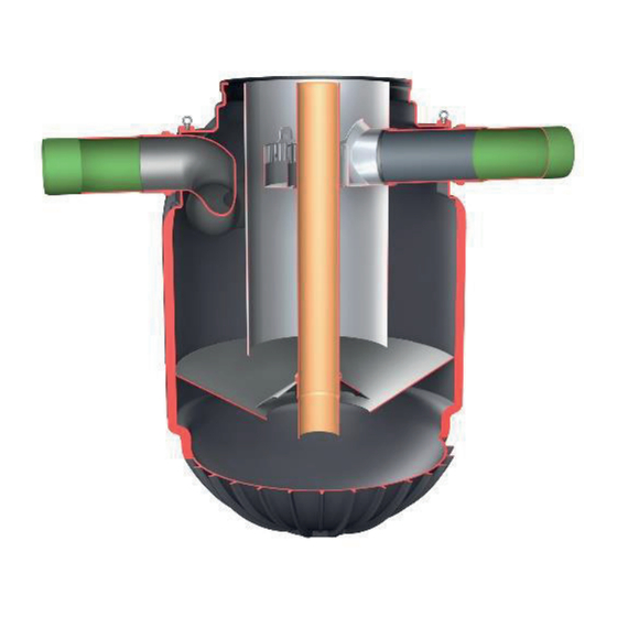
Page 8: Ecoloop Sp Schnittzeichnung
4 Technische Daten EcoLoop SP Schnittzeichnung Alle Angaben in mm. 8 / 76... -
Page 9: Einbau Und Montage
Anschlussleitungen Der GRAF EcoLoop SP ist stoßfrei, in waagerechter Lage in die vorbereitete Baugrube einzubringen und mit den entsprechenden Leitungen zu verbinden. Vorab sind die für die Lagerung und den Transport mon- tierten Verschlusskappen vom Zu- und Ablaufrohr der Anlage zu entfernen. Zu- als auch Ablaufleitung sind mit einem geringen Gefälle von 0,6 % auszubilden. -
Page 10: Verfüllen Der Baugrube
5 Einbau und Montage Verfüllen der Baugrube Die Anlage ist stoßfrei und mit geeignetem Gerät in die vorbereitete Baugrube einzubringen. Vor dem Einbringen des Verfüllmaterials in die Baugrube wird die Anlage zu 1/3 mit Wasser ge- füllt. Danach wird das Verfüllmaterial (Rundkorn- kies max. -
Page 11: Endmontage
5 Einbau und Montage Endmontage Betonabdeckung Teleskop Dichtung für Zwischenstück Zwischenstück* Profildichtung ⑥ Anlage *Es können bis zu zwei Zwischenstücke mit entsprechender Dichtung verbaut werden. Das Teleskop kann auch ohne Zwischenstück direkt eingesetzt werden. 11 / 76... -
Page 12: Montage Teleskop-Domschacht Auf Dem Tank
5 Einbau und Montage 5.8.1 Montage Teleskop-Domschacht auf dem Tank Der Teleskop-Domschacht ermöglicht ein stufen- loses Anpassen der Anlage an gegebene Gelän- deoberflächen. Zur Montage des Teleskop-Dom- schachtes auf der Anlage wird die Profildichtung ⑤ auf die Tanköffnung montiert. Die Profildich- tung (Material EPDM) des Schachtdoms wird großzügig mit Schmierseife (keine Schmierstoffe auf Mineralölbasis verwenden, da diese die Dich-... -
Page 13: Begehbar
5 Einbau und Montage Begehbar Wichtig: Um das Übertragen von Lasten auf die Anlage zu verhindern, wird das Teleskop ① lagen- weise mit Rundkornkies ② (max. Körnung 8/16) angefüllt und gleichmäßig verdichtet. Dabei ist eine Beschädigung des Doms ③ bzw. Teleskops zu vermeiden. -
Page 14: Schwerlast-Befahrbarkeit
5 Einbau und Montage 5.11 Schwerlast-Befahrbarkeit Bei einer Schwerlast-Befahrbarkeit ist eine stati- sche Lastverteilungsplatte bauseits zu erstellen. Auf Anfrage sind bei der Otto Graf GmbH hierzu Bewährungspläne erhältlich. ② Bei Installation unter Schwerlastbefahrenen Flä- chen wird das Teleskop ① mit einer Lastvertei- lungsplatte unterbaut. -
Page 15: Kontrolle Und Wartung
6 Kontrolle und Wartung Kontrolle und Wartung Wartungsintervalle Um die Reinigungsfunktion der Anlage zum Schutz der Wasserqualität aufrecht zu erhalten, sind regelmä- ßige Wartungen erforderlich. Die Länge der Wartungsintervalle ist von der örtlichen Verschmutzung des Niederschlagswassers abhängig. Um die Verschmutzungssituation einschätzen zu können, sind zu Beginn häufigere, z.B. - Page 16 6 Kontrolle und Wartung Tabelle 2: Füllstand Schlammfang EcoLoop Saphir Abstand a Schlammhöhe Füllstand Schlammvolumen Wartung erforderlich? [mm] [mm] 1360 Ja, sehr dringend 1380 Ja, sehr dringend 1400 Ja, dringend 1430 Nicht dringend 1480 Nein 1530 Nein Abmessen des Schlammspiegels mit Peilteller und Peilstab 1.
-
Page 17: Durchführung Der Wartung
6 Kontrolle und Wartung Durchführung der Wartung Das gesamte Sammelvolumen der Anlage muss abgesaugt und anschließend neu befüllt werden, um die Funktionsfähigkeit der Anlage durchgängig sicherzustellen. Dabei ist die untenstehende Reihenfolge zu beachten. Die Wartung sollte möglichst bei trockenem Wetter stattfinden. Auf Verkehrsflächen ist die Ein- satzstelle abzusichern. - Page 18 6 Kontrolle und Wartung Entsorgung des Absaugvolumens Die fachgerechte Entsorgung erfolgt durch das Wartungsunternehmen. Wird die Wartung selbst durchge- führt, ist der abtrennbare Müll entsprechend gesetzlichen Vorschriften als Kunststoff-, Rest- oder Sonder- müll zu entsorgen. Der Flüssiganteil mit darin enthaltenen Feinstoffen ist in den Schmutzwasserkanal zu leiten.
-
Page 19: Anhang
Anlage, Ort: _____________________, Datum der Inbetriebnahme: ____________________ Max. Höhe Wurde Wurde Frisch- Schlammhöhe Abstand a nach Tabelle 2 Schlamm ent- wasser wieder Datum gemessen [mm] erreicht? nommen? aufgefüllt? [ja/nein] [ja/nein] [ja/nein] [ja/nein] www.graf.info 19 / 76 2023-02... - Page 20 Installation and servicing for the GRAF EcoLoop SP 1100 DN 200 EcoLoop SP 1100 DN 200 Order no. 470030 Contents The points described in these in- GENERAL INFORMATION structions must be observed in Safety all cases. Failure to do so will in- TRANSPORT, STORAGE AND UNLOADING validate any warranty claim.
-
Page 21: The
The system cover must always be kept closed, except during work in the system, otherwise there is a high risk of accidents. GRAF provides an extensive range of accessories, which are all coordi- nated and can be combined to form complete systems. Using accessory parts not approved by GRAF will render the warranty/guarantee null and void. -
Page 22: Transport, Storage And Unloading
Under no circumstances should the system be raised on piping or other components. At the installation site, the GRAF EcoLoop SP can be moved with a lightweight device. Before installation, check the EcoLoop SP system and its accessories for completeness and damage. -
Page 23: Installation Conditions
3 Installation conditions Installation conditions Please note: Information on the minimum installation depth without taking frost-free limits into account! All dimensions are in mm. 23 / 76... - Page 24 3 Installation conditions Please note: The maximum earth covering of The GRAF EcoLoop SP can only be installed in 4 m must not be exceeded. groundwater and stratum water to a limited ex- tent. Please refer to point 5.7 of these instruc- tions.
-
Page 25: Technical Data
4 Technical data Technical data EcoLoop SP exterior Inlet Outlet Table 1 – Technical data EcoLoop SP Operating capacity Diameter D [mm] 1155 Height H [mm] 1685 25 / 76... -
Page 26: Ecoloop Sp Sectional Drawing
4 Technical data EcoLoop SP sectional drawing ⌀ unobstructed All dimensions are in mm. 26 / 76... -
Page 27: Installation And Assembly
150 mm). Connecting pipes The GRAF EcoLoop SP is to be moved gently in a horizontal position into the prepared excavation pit and connected to the appropriate pipes. In advance, the caps fitted for storage and transport must be removed from the inlet and outlet pipes of the tank. -
Page 28: Filling The Trench
5 Installation and assembly Filling the trench Suitable equipment should be used to move the system gently into the prepared pit. Before introducing the backfill material into the ex- cavation pit, the system is filled 1/3 with water. Subsequently, the backfill material (round grain gravel, max. -
Page 29: Final Assembly
5 Installation and assembly Final assembly Concrete cover Telescopic dome shaft Seal for extension sleeve Extension sleeve Profile seal ⑥ System *It is possible to install up to two extension sleeves with the appropriate seal. The telescopic dome shaft can also be used directly without an extension sleeve. 29 / 76... -
Page 30: Installation Of Telescopic Dome Shaft On The Tank
5 Installation and assembly 5.8.1 Installation of telescopic dome shaft on the tank The telescopic dome shaft allows infinite adjust- ment of the system to given terrain surfaces. To install the telescopic dome shaft on the system, the profile seal ⑤ is fitted to the tank opening. The profile seal (material EPDM) of the shaft dome is rubbed in with plenty of soft soap (do not use lub- ricants with a mineral oil base because they will... -
Page 31: Suitable For Pedestrian Loading
5 Installation and assembly Suitable for pedestrian loading Important: To prevent loads from being transferred to the system, the telescopic dome shaft ① is filled in layers with round gravel ② (max. grain 8/16) and evenly compacted. Avoid damaging the dome ③ and/or telescope. -
Page 32: Suitability For Heavy Goods Vehicles
Load bearing capability plans for this are availa- ble from Otto Graf GmbH on request. ② If installing under surfaces driven on by heavy goods vehicles, a load distribution plate is used to support the telescopic dome shaft ①. -
Page 33: Inspection And Maintenance
6 Inspection and maintenance Inspection and maintenance Maintenance intervals The system must be serviced regularly if it is to continue maintaining water quality. The servicing intervals depends on the contamination levels of the local precipitation. Shorter inspection intervals are recom- mended at the beginning for the purpose of assessing contamination levels. -
Page 34: Servicing The System
6 Inspection and maintenance Distance a Sludge height Level Sludge volume Maintenance neces- [mm] [mm] sary? 1360 Yes, very urgently 1380 Yes, very urgently 1400 Yes, urgently 1430 Not urgently 1480 1530 Measuring the sludge level with metering plate and dipstick 1. - Page 35 6 Inspection and maintenance Note: We recommend commissioning professionals to service the system. Enter “separator maintenance services” in your preferred search engine for maintenance companies near you. Extraction procedure 1. Open the shaft cover 2. Use the extractor to remove light and coarse sol- ids.
- Page 36 6 Inspection and maintenance The commissioned maintenance company is responsible for disposing of the extracted volume. Otherwise, the separable waste must be disposed of as plastic, other, or special waste as set down in the applicable laws. The liquid fraction and its fine solids content must be discharged into the sewer. Under no circumstances may untreated water be directed into ground or surface water.
-
Page 37: Annex
System, location: _____________________, date of commissioning: ____________________ Has the sys- Max height in Has sludge Sludge level tem been re- Distance a Table 2 been re- Date measured filled with fresh [mm] reached? moved? [yes/no] water? [yes/no] [yes/no] [yes/no] www.graf.info 37 / 76 2023-02... - Page 38 Notice d’installation et de maintenance d' Ecoloop GRAF SP 1100 DN 200 EcoLoop SP 1100 DN 200 Réf. 470030 Table des matières Les points décrits dans cette no- CONSIGNES GENERALES tice d’installation devront être Sécurité scrupuleusement respectés. TRANSPORT, STOCKAGE ET DECHARGEMENT Tout manquement à...
-
Page 39: Consignes Generales
éviter le risque d’accident. La société GRAF propose un large assortiment d’accessoires adaptés les uns aux autres et pouvant être assemblés en système complet. GRAF décline toute prise en charge sous garantie en cas d’utilisation d’accessoires non conformes. Remarque: L'évaluation selon M 153 / A 102 concerne la performance de nettoyage. -
Page 40: Transport, Stockage Et Dechargement
œillets de levage prévus à cet effet. Le système ne doit en aucun cas être soulevé par la tuyauterie ou d’autres éléments. Sur le site d’installation, GRAF EcoLoop SP peut être déplacé avec un équipement léger. Vérifier avant l’installation que le système EcoLoop SP et ses accessoires sont complets et en bon état. -
Page 41: Conditions D'installation
3 Conditions d’installation Conditions d’installation Attention: Indications sur la profondeur minimale d’installation hors conditions hors gel ! Toutes les données sont indiquées en mm. 41 / 76... - Page 42 3 Conditions d’installation Attention : La hauteur maximale de recouvre- GRAF EcoLoop SP peut être installé dans une ment de 1200 mm ne doit pas être dépassée. nappe phréatique uniquement sous conditions. Veuillez impérativement respecter le point 5.7 de la notice.
-
Page 43: Donnees Techniques
4 Données techniques Données techniques EcoLoop SP Vue de l'extérieur Entrée Sortie Tableau 1 : Données techniques EcoLoop SP Volume nominal Diamètre D [mm] 1155 Hauteur H [mm] 1685 43 / 76... -
Page 44: Plan En Coupe Ecoloop Sp
4 Données techniques Plan en coupe EcoLoop SP Ø 645 mm d’ouverture libre Toutes les données sont indiquées en mm. 44 / 76... -
Page 45: Installation Et Montage
Mettre en place un lit de pose en graviers ronds (grain max. 8/16 mm, épaisseur 150 mm). Raccordement GRAF EcoLoop SP doit être installé sans impact et en position horizontale dans la fouille, puis raccordé aux conduites correspondantes. Veillez à d’abord retirer les capuchons placés sur les tuyaux d’entrée et de sortie. -
Page 46: Remblai De La Fouille De Construction
5 Installation et montage Remblai de la fouille de construction Le système doit être installé dans la fouille du chantier sans impact avec un matériel adapté. Avant d’introduire le matériau de remblai dans la fouille de chantier, le système doit être rempli au tiers avec de l’eau. -
Page 47: Montage Final
5 Installation et montage Montage final Couvercle en béton Rehausse télescopique Joint pour rallonge Rallonge* Joint profilé ⑥ Système EcoLoop * Installation possible avec 2 rallonges avec joint approprié. La rehausse télescopique peut également être utilisé directement sans rallonge. 47 / 76... -
Page 48: Montage De La Rehausse Télescopique Sur La Cuve
5 Installation et montage 5.8.1 Montage de la rehausse télescopique sur la cuve La rehausse télescopique permet un ajustement facile et précis du système par rapport au niveau du sol. Placer le joint d’étanchéité ⑤ sur la gorge de l’ou- verture de la cuve comme indiqué. -
Page 49: Passage Piétons
5 Installation et montage Passage piétons Important : Pour éviter le transfert des charges sur le système, le pourtour de la rehausse télescopique ① est remblayé avec des couches de gravier rond ② (grain max. 8/16) compactées de manière ho- mogène. -
Page 50: Passage Camions
5.11 Passage camions En cas de passage camions, le client doit installer une dalle de répartition de charge statique. Sur demande, Otto Graf GmbH peut fournir des ② plans d’armature à cette fin. Pour une installation avec passage poids lourds, sceller la rehausse télescopique ①... -
Page 51: Verification Et Maintenance
6 Vérification et maintenance Vérification et maintenance Intervalles de maintenance Pour assurer le bon fonctionnement de traitement des eaux pluviales du système, des maintenances régu- lières sont nécessaires. La cadence des interventions de maintenance dépend de la pollution locale des eaux pluviales. - Page 52 6 Vérification et maintenance Distance a Hauteur des Niv. de remplis- Volume des Maintenance néces- [mm] boues [mm] sage [%] boues [l] saire ? 1360 Oui, absolument ur- gente 1380 Oui, absolument ur- gente 1400 Oui, urgente 1430 Non urgente 1480 1530 Mesurer le niveau des boues avec un disque de mesure et une tige...
-
Page 53: Réalisation De L'inspection
6 Vérification et maintenance Réalisation de l’inspection Le volume total du système doit être aspiré puis rempli d’eau fraiche afin d'assurer la fonctionnalité perma- nente du système. Veuillez respecter la chronologie ci-dessous. La maintenance devrait avoir lieu de pré- férence par temps sec. Sécuriser l’accès du système si passage véhicules. Remarque : Il est recommandé... - Page 54 6 Vérification et maintenance Recyclage de la vidange La vidange est confiée à une entreprise de maintenance. Si la maintenance est effectuée par vos soins, les déchets recyclables doivent être triés conformément aux réglementations en vergeures (déchets plas- tiques, résiduels ou spéciaux). Le partie liquide contenant des fines particules doit être rejetée à l'égout. Le rejet des eaux polluée non traitée dans les eaux souterraines et superficielles ne sont pas autorisées.
-
Page 55: Annexe
Installation, localité :_____________________, date de la mise en service : ____________________ Hauteur des Hauteur max. Prélèvement Rajout de l’eau boues mesu- Distance a atteinte selon Date de boues ? claire? rée [mm] Tableau 2 ? [oui/non] [oui/non] [oui/non] [oui/non] www.graf.info 55 / 76 2023-02... - Page 56 Manual de instrucciones para la instalación y el mantenimiento del GRAF EcoLoop SP 1100 DN 200 EcoLoop SP 1100 DN 200 N.º ref. 470030 Índice de contenidos Es obligatorio atenerse a las indi- INFORMACIÓN GENERAL caciones descritas en este ma- Seguridad nual.
-
Page 57: Información General
GRAF ofrece una amplia gama de accesorios, todos ellos compatibles entre sí y ampliables para formar sistemas completos. El uso de acceso- rios no autorizados por GRAF, tendrá como consecuencia la anulación de la garantía. -
Page 58: Transporte, Almacenamiento Y Descarga
Bajo ninguna circunstancia se debe levantar el sistema por las tuberías. Ya en el emplazamiento de la instalación, el GRAF EcoLoop SP se puede desplazar con ayuda de un dispositivo ligero. Antes de la instalación, revise el sistema EcoLoop SP y sus accesorios para comprobar que estén completos y no presenten daños. -
Page 59: Condiciones De Instalación
3 Condiciones de instalación Condiciones de instalación Atención: Información sobre la profundidad mínima de instalación ¡sin tener en cuenta la cota de helada! Todas las indicaciones se ofrecen en mm. 59 / 76... - Page 60 3 Condiciones de instalación Atención: No se debe exceder la cobertura de El sistema GRAF EcoLoop SP solo se puede ins- tierra máxima de 1200 mm. talar en suelos con aguas freáticas o estratos de agua bajo determinadas condiciones. Asegúrese de respetar el punto 5.7 de estas instrucciones.
-
Page 61: Datos Técnicos
4 Datos técnicos Datos técnicos Vista exterior de EcoLoop SP Entrada Salida Tabla 1: Datos técnicos EcoLoop SP Volumen operativo [Litros] Diámetro D [mm] 1155 Altura Alto [mm] 1685 61 / 76... -
Page 62: Sección De Ecoloop Sp
4 Datos técnicos Sección de EcoLoop SP Ø int. 645 (interior) Todos los datos en mm. 62 / 76... -
Page 63: Instalación Y Montaje
150 mm). Tuberías de conexión El EcoLoop SP de GRAF debe instalarse en posición horizontal, sin que reciba impactos, en la fosa de excavación preparada y conectarse a las tuberías correspondientes. Las tapas colocadas en los conductos de entrada y salida del sistema sirven como ayuda para el almacenamiento y transporte y deben retirarse previamente a la instalación. -
Page 64: Relleno De La Excavación
5 Instalación y montaje Relleno de la excavación Se debe introducir el sistema en la excavación preparada con la ayuda de maquinaria apropiada y sin que sufra golpes. Antes de introducir el material de relleno en la ex- cavación, se debe llenar 1/3 del sistema con agua. Luego el material de relleno (gravilla de grano re- dondo de granulación máxima de 8/16) se dispone por capas de, como máximo, 30 cm hasta el borde... -
Page 65: Montaje Final
5 Instalación y montaje Montaje final Cubierta de hormigón Tubo telescópico Junta para pieza intermedia Pieza intermedia* Sellado de junta ⑥ Sistema *Se pueden instalar hasta dos piezas intermedias con las juntas correspondientes. El tubo telescópico también se puede usar directamente sin pieza intermedia. 65 / 76... -
Page 66: Montaje De La Cubierta Telescópica En El Depósito
5 Instalación y montaje 5.8.1 Montaje de la cubierta telescópica en el depósito La cubierta telescópica permite la adaptación con- tinua del sistema a determinadas superficies del terreno. Para el montaje de la cubierta telescópica en el sistema, disponga la junta de perfil ⑤ en la apertura del depósito. -
Page 67: Transitable Por Peatones
5 Instalación y montaje Transitable por peatones Importante: Para evitar que se transmitan cargas al sistema, se rellena y se compacta el espacio al- rededor del tubo telescópico ① con capas de gra- villa de grano redondo ② (granulación máxima 8/16) de manera uniforme. -
Page 68: Transitable Por Vehículos Pesados
Los planos de refuerzo los encontrará disponi- bles en Otto Graf GmbH. ② En caso de que la instalación se emplace bajo superficies transitadas por vehículos pesados, el tubo telescópico deberá... -
Page 69: Inspección Y Mantenimiento
6 Inspección y mantenimiento Inspección y mantenimiento Periodicidad del mantenimiento Con el fin de mantener la función de purificación del sistema para proteger la calidad del agua, se requiere un mantenimiento periódico. La duración de los intervalos de mantenimiento depende de la contaminación local del agua de lluvia. - Page 70 6 Inspección y mantenimiento Tabla 2: Nivel de llenado del colector de fangos EcoLoop Saphir Distancia a Altura del fango Nivel de llenado Volumen ¿Necesita manteni- [mm] [mm] fango miento? 1360 Sí, muy urgente 1380 Sí, muy urgente 1400 Sí, urgente 1430 No urge 1480...
-
Page 71: Realización Del Mantenimiento
6 Inspección y mantenimiento Realización del mantenimiento Todo el volumen de recogida del sistema debe ser extraído y luego rellenado para garantizar que el sistema siga funcionando correctamente. Debe seguirse la secuencia que se indica a continuación. Si es posible, el mantenimiento debe realizarse en tiempo seco. - Page 72 6 Inspección y mantenimiento La empresa de mantenimiento se encarga de su correcta eliminación. Si el mantenimiento lo realiza la propia empresa, los residuos separables deben eliminarse como residuos plásticos, residuales o especia- les de acuerdo con la normativa legal. La fracción líquida y las partículas finas que contiene deben ser descargadas al alcantarillado.
-
Page 73: Adjunto
¿Se ha alcan- ¿Se han elimi- ¿Se ha re- Nivel de fango zado la altura Distancia a nado los fan- puesto el agua Fecha medido máxima según [mm] gos? dulce? [sí/no] Tabla 2? [sí/no] [sí/no] [sí/no] www.graf.info 73 / 76 2023-02... - Page 74 Notizen / Notes / Notas 74 / 76...
- Page 75 75 / 76...
- Page 76 4 0 2 3 1 2 2 2 8 8 3 3 6 963251 | 1 76 / 76...
Need help?
Do you have a question about the EcoLoop SP 1100 DN 200 and is the answer not in the manual?
Questions and answers