Table of Contents
Advertisement
Available languages
Available languages
Quick Links
ECO BLOC INSPECT FLEX
Anleitung für den Einbau des
DE
GRAF EcoBloc Inspect flex
>> Seite 1-16
Instructions for installation
EN
GRAF EcoBloc Inspect flex
>> Page 17-32
Notice d'installation
FR
EcoBloc Inspect flex GRAF
>> Page 33-48
Instrucciones para el montaje del
ES
GRAF EcoBloc Inspect flex
>> Página 49-64
Advertisement
Chapters
Table of Contents

Related Manuals for Graf ECO BLOC INSPECT FLEX


Summary of Contents for Graf ECO BLOC INSPECT FLEX
- Page 1 ECO BLOC INSPECT FLEX Anleitung für den Einbau des GRAF EcoBloc Inspect flex >> Seite 1-16 Instructions for installation GRAF EcoBloc Inspect flex >> Page 17-32 Notice d‘installation EcoBloc Inspect flex GRAF >> Page 33-48 Instrucciones para el montaje del GRAF EcoBloc Inspect flex >>...
-
Page 2: Table Of Contents
Nichtbeachtung erlischt jeglicher Hinweise zum Betrieb der Anlage Garantieanspruch. Für alle über ALLGEMEINE PRODUKTHINWEISE GRAF bezogenen Zusatzartikel erhalten Sie separate in der TECHNISCHE DATEN Transportverpackung Technische Daten zum GRAF EcoBloc Inspect flex beiliegende Einbauanleitungen. Technische Daten GRAF EcoBloc Inspect Bodenplatte TRANSPORT &... -
Page 3: Allgemeine Hinweise
Des Weiteren sind bei Einbau, Montage und Reparatur die einschlägigen Vorschriften und Normen, wie z.B. DIN 18300 “Erdarbeiten” und DIN 4124 “Baugruben und Gräben”, zu beachten. GRAF bietet ein umfangreiches Sortiment an Zubehörteilen, die alle aufeinander abgestimmt sind und zu kompletten Systemen ausgebaut werden können. Die Verwendung nicht von GRAF freigegebener Zubehörteile führt zu einem Ausschluss der Gewährleistung/Garantie. -
Page 4: Allgemeine Produkthinweise
GRAF VS-Verteilermodul DN 400 330340 GRAF VS-Zulaufmodul DN 600 330360 GRAF VS-Zwischenstück DN 600 371003 GRAF VS-Verteilermodul DN 600 330361 Zubehör Entlüftungsabschluss DN 100 369017 Inspektionsabschluss DN 200 340527 GRAF-Tex Geotextil , 1 lfm = 5m² 231002 3 / 64... -
Page 5: Technische Daten
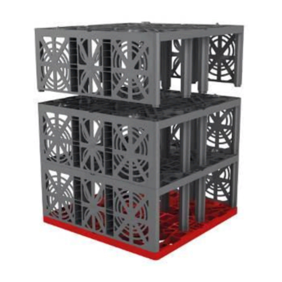
3. Technische Daten Technische Daten Technische Daten zum GRAF EcoBloc Inspect flex Volumen (Brutto/Netto) 205 Liter / 195 Liter Maße (LxBxH) 800 x 800 x 320 mm Anschlüsse 4 x DN 200/DN 150/DN 100 + 4 x DN 100 Gewicht... -
Page 6: Transport & Lagerung
Modulen gelagert und transportiert. Die Grundmaße der Verpackungseinheiten betragen immer 0,8 m x 0,9 m. GRAF EcoBloc Inspect flex Bodenplatten befinden sich üblicherweise auf einer seperaten Palette. Der Transport kann mit Gabelstapler o.ä. Gerät bis zum Aufstellungsort erfolgen. Am Aufstellungsort können die Rigolenelemente und Bodenplatten von Hand oder leichtem Gerät versetzt werden. -
Page 7: Standortwahl
5. Standortwahl Standortwahl Standort Der Standort der Versickerungsanlage ist so zu wählen, dass austretendes Wasser keine Beschädigungen an Gebäuden oder weiteren Installationen verursacht. Um ein Unterspülen und Anstauen zu vermeiden, sind Versickerungsanlagen stets in einer Entfernung von mind. 1,5-facher Baugrubentiefe zu platzieren. A‘... -
Page 8: Abmessungen Der Baugrube
5. Standortwahl Abmessungen der Baugrube Die Dimensionierung der Rigole erfolgt gemäß Arbeitsblatt DWA A-138 (siehe 1.1). Für eine kostenfreie Dimensionierung kontaktieren Sie uns. Die Abmessung der Baugrubensohle richtet sich nach der o. g. Dimensionierung wie folgt: Länge der Rigole (Dimensionierung) + 1 m Arbeitsraum (umlaufend) Breite der Rigole (Dimensionierung) + 1 m Arbeitsraum (umlaufend) -
Page 9: Belastungsklassen
Belastungsklassen PKW, LKW12, SLW30, SLW40 und SLW60. In Tabelle 1 sind die min. und max. Erdüberdeckungen der verschiedenen Belastungsklassen abgebildet. Abweichende Einbausituationen sind grundsätzlich mit GRAF abzustimmen. Es werden Füllmaterialien (wiederverwendetes Aushubmaterial und/oder Kies) mit einer maximalen Dichte von 20kN/m³ vorausgesetzt. -
Page 10: Einbau
7. Einbau Einbau Die Abmessung der Baugrube richten sich nach den Dimensionen der Versickerungsanlage sowie einem umlaufenden Arbeitsraum von ca. einem Meter Breite, siehe Kapitel 5.3. Baugrube vorbereiten Baugrubensohle muss grundsätzlich waagrechtes, ebenes und tragfähiges Planum vorbereitet werden. Spitze Gegenstände, größere Steine oder ähnliche... -
Page 11: Positionieren Der Rigolenelemente
7. Einbau Positionieren der Rigolenelemente Die Rigolenelemente werden in die Bodenplatte gesteckt. Die Eco Verbindungselemente werden ebenfalls in jeder Lage zur Verbindung verwendet. Der EcoBloc Inspect flex wird vorzugsweise mit Inspektionskanal (offene Seite) Längsrichtung gelegt. Für eine endplattenoptimierte Verlegeart werden die Blöcke, die den Abschluss des Systems in der Breite bilden, um 90°... -
Page 12: Zulauf Montieren
Anschließend werden die Endplatten montiert, diese lassen sich einfach in die bestehende Öffnung am EcoBloc Inspect flex einrasten. Die Endplatten sind so einzusetzen, dass das GRAF Logo mit der Schreibrichtung übereinstimmt. Für Zuläufe lassen sich an der Eco Endplatte Anschlüsse in DN 100, DN 150 oder DN 200 realisieren. -
Page 13: Inspektionskanal Anschließen
7. Einbau Analog hierzu werden die notwendigen Entlüftungen angebracht. Die vertikal ausgerichteten Entlüftungen können mit Hilfe eines 90° KG Bogens an die horizontale Bohrfläche angebracht werden. Inspektionskanal anschließen Grundsätzlich sind die Böden der Rigolenelemente inspizier- und befahrbar. Bitte verwenden Sie daher die unteren Anschlüsse in den Endplatten in Verlegerichtung für... -
Page 14: Aufbau Als Retentionsbehälter
Angestautes Grundwasser kann zum Auftrieb des Systems und damit zu dessen Beschädigung und der der Umgebung führen. Ein Einbau im Grundwasser ist vorab mit der Firma GRAF abzusprechen. Notwendige Angaben zum Bauvorhaben (Erdüberdeckung, Grundwasserstand, Belastung M) sind der Firma GRAF entsprechend mitzuteilen und abzustimmen. -
Page 15: Einbau Unter Befahrbarer Verkehrsfläche Bis Slw60
9. Einbau unter befahrbarer Verkehrsfläche bis SLW60 Einbau unter befahrbarer Verkehrsfläche bis SLW60 Decke + nach RStO 12 Tragschicht gemäß RStO 12 ▼E =45MN/m² Frostschutzschicht min. 800 mm / Erdüberdeckung gemäß RStO 12 Einbauanleitung EcoBloc System ▼E =25MN/m² Sauberkeits- 8-10cm schicht Verkehrsflächen bis SLW60 sind nach den gängigen Richtlinien (z.B. -
Page 16: Befahren Mit
Walzenzüge, Bagger Gesamtgewicht: ca. 12t min. 0,5 verteilt auf: Gleichmäßig, auf 2 Walzen Dimension: 5,9 x 2,3 min. 0,8 SLW 60 Fahrzeuge Bitte halten Sie bei Abweichung von den hier genannten Materialien und Geräten Rücksprache mit GRAF. 15 / 64... -
Page 17: Sonstige Anwendungfälle
Die vorliegende Dokumentation behandelt ausschließlich die Verwendung der GRAF EcoBloc Inspect flex Rigolenkörper zur Rückhaltung, Speicherung oder Versickerung von Niederschlagswasser. Jegliche anderweitige Nutzung der Rigolenkörper ist mit der Otto GRAF GmbH hinsichtlich technischer, stofflicher und/oder statischer Betrachtung abzustimmen. Des Weiteren empfiehlt sich, bei speziellen Anforderungen die Kontaktaufnahme mit Architekten oder Planern mit Kenntnissen im Bereich Hydrologie und Geologie. - Page 18 GENERAL PRODUCT INFORMATION transportation packaging for all TECHNICAL DATA additional articles purchased from Technical data for the GRAF EcoBloc Inspect flex GRAF. Technical data for the GRAF EcoBloc Inspect flex TRANSPORT AND STORAGE Transport and storage...
- Page 19 An infiltration/attenuation system is usually sized in accordance with national standards. You can request free sizing from Graf. In particular the permeability of the surrounding soil is of great significance and may result in problems with and damage to the Graf infiltration & attenuation system if calculated incorrectly.
- Page 20 GRAF VS connecting piece DN 600 (23.6”) 371003 GRAF VS distributor module DN 600 (23.6”) 330361 Accessories DN 100 venting end 369017 DN 200 Inspection end 340527 GRAF-tex geo textile, material sold by metre, roll width 5m 231002 19 / 64...
- Page 21 3. Technical data Technical data Technical data for the GRAF EcoBloc Inspect flex Volume (gross/net) 205 litres/195 litres (54.2/51.5 US-gal.) Dimensions (LxWxH) 800 x 800 x 320 mm (31.44” x 31.44” x 12.6”) 4 x DN 200/DN 150/DN 100 + 4 x DN 100 (4 x 8“/6“/4“ + 4 x 4“)
- Page 22 11.5”) GRAF EcoBloc Inspect flex ground plates are usually located on a separate pallet. The Graf EcoBloc Inspect flex system elements can be transported to the installation location with a fork lift truck or similar equipment. At the installation location, the EcoBloc Inspect and baseplates can be moved manually or with light-duty equipment.
- Page 23 5. Location options Location options Location The location of an infiltration system should be such that percolating water does not cause damage to buildings or other installations. To avoid erosion and accumulation, an infiltration system should be located at a distance of at least 1.5 times the installation depth. A‘...
- Page 24 5. Location options Installation dimensions The excavation is sized according to national standards (refer to chapter 1.1). Please contact Graf or your local distributor for free sizing. The dimensions of the excavation bed for good working practice are as follows: Excavation length (sizing) + 1 m (3’–3.4”) working space (all round)
- Page 25 The minimum and maximum earth coverings for the various loading classes are shown in Table 1. Deviating installation situations should always be discussed with GRAF. System covering (reuse excavated material and/or gravel) with a maximum weight of unit volume of 20kN/m³...
- Page 26 7. Installation Installation The size of the excavation depends on the dimensions of the EcoBloc Inspect system, leaving a working space of around one metre all the way round, see chapter 5.3. Construction & installation of an infiltration tank The excavation bed must always be prepared as a horizontal, level pit with load-bearing capacity.
- Page 27 EcoBloc In- spect flex. The end plates must be inserted, so that GRAF Logo is in accordance with the writing direction. DN 100 (4” pipe), DN 150 (6” pipe) or DN 200 (8” pipe) connections can be produced for inlets on the Eco end plate.
- Page 28 7. Installation Once all the blocks are positioned, the system is fully wrapped in geotextile. This prevents the ingress of dirt particles into the system. Please note: There is an increased risk of slipping on EcoBloc Inspect system in frosty and wet conditions. Fitting inlet On the inlet surface, an X is cut into the geo textile.
- Page 29 7. Installation Covering the EcoBloc Inspect system Before filling the installation, all inlets, vents and shafts must be connected. Before backfilling en- sure that the geotextile is not pulled apart. Over- laps must remain in place when filling. The EcoBloc Inspect system must not be driv- en over directly with construction machinery.
- Page 30 When installing the retention system, check again that no compression of the subsoil or silting-up has taken place during the construction phase. It may be necessary to install extra drainage. GRAF will be happy to provide advice on this. 29 / 64...
- Page 31 9. Installation under traffic areas up to HGV60 Installation under traffic areas up to HGV60 HGV60 Cover bearing acc. na tional layer acc. national standards standards ▼E =45MN/m² Frost protec- tion layer + min. 800 mm earth cover- ing acc. na- tional stand- ards EcoBloc...
- Page 32 0.5 m (1’-7.68”) Distributed: evenly, over 2 rollers Dimension: 5.9 m x 2.3 m (19’-4.32” x 7’-6”) min. 0.8 m (2’-7.44”) HGV60 (HS-25) Please contact GRAF in the event of deviation from the materials and equipment stated here. 31 / 64...
- Page 33 11. Other applications 11. Other applications This documentation only relates to use of the GRAF EcoBloc Inspect flex for infiltration and attenuation systems for retaining, storing or infiltrating surface or rainwater. Any other use of the EcoBloc Inspect system must be agreed with Otto GRAF GmbH from a technical, material and/or static consideration.
- Page 34 Lisez également toutes Données techniques de l’EcoBloc Inspect flex les notices des autres éléments Données techniques de plaque de fond pour EcoBloc fournis par la société GRAF. Vous Inspect flex trouverez les notices de montage jointes dans l’emballage.
-
Page 35: Généralités
« Travaux de terrassement à ciel ouvert », pour l’installation, la pose et l’entretien de l’ouvrage. GRAF propose un large assortiment d’accessoires adaptés les uns aux autres et pouvant être assemblés en systèmes complets. GRAF décline toute prise en charge sous garantie en cas d’utilisation d’accessoires non conformes. -
Page 36: Informations Produit
Rallonge pour regard VS DN 600 GRAF 371003 Regard de répartition VS - DN 600 GRAF 330361 Accessoires Event DN 100 369017 Regard d’inspection DN 200 340527 Géotextile GRAF-Tex, 1 ML = 5m² (rouleau de 5m de large) 231002 35 / 64... -
Page 37: Données Techniques
3. DONNÉES TECHNIQUES DONNÉES TECHNIQUES Données techniques de l’EcoBloc Inspect flex Volume (brut/net) 205 l / 195 l Dimensions (longueur x largeur x hauteur) 800 x 800 x 320 mm Raccordements 4 x DN 200/DN 160/DN 110 + 4 x DN 110 Poids 8 kg Matériau... -
Page 38: Transport & Stockage
4. TRANSPORT & STOCKAGE TRANSPORT & STOCKAGE Transport et stockage Les éléments d’ouvrage d‘infiltration ou de rétention EcoBloc Inspect flex sont stockés et transportés en lots emballés de 14 ou bien 16 éléments ; avec pour dimensions au sol 0,8 m x 0,9 m. Les plaques de fond EcoBloc Inspect flex sont habituellement conditionnées et transportées sur une palette séparée. -
Page 39: Choix De L'emplacement
5. CHOIX DE L’EMPLACEMENT CHOIX DE L’EMPLACEMENT Emplacement Choisissez l’emplacement de l‘ouvrage d’infiltration de sorte à ce que de l’eau s’en écoulant ne puisse pas endommager ni bâtiment ni autre installation à proximité. Afin d’empêcher érosion, ravinement ou affouillement, les ouvrages d’infiltration doivent être implantés à une distance équivalente à une fois et demi leur profondeur d’enfouissement. -
Page 40: Dimensions De La Fouille
5. CHOIX DE L’EMPLACEMENT Dimensions de la fouille Le dimensionnement de l’ouvrage d’infiltration pourra être réalisé selon la fiche de calcul DWA A-138 (confer 1.1). Veuillez nous contacter pour un dimensionnement. Les dimensions de la fouille sont déterminées d’après le dimensionnement ci-dessus et comme suit : - Longueur de l’ouvrage (donnée par le dimensionnement) + 1 m d’espacement de travail (tout autour de l’ouvrage) - Largeur de l’ouvrage (donnée par le dimensionnement) + 1 m d’espacement de travail (tout... -
Page 41: Classes De Charge
≤ 12 t, poids lourds ≤ 30 t, ≤ 40 t ou ≤ 60 t. Les recouvrements max et min des différentes classes de charge sont repris dans le tableau 1. Tout autre type d’implantation doit toujours être réalisé en concertation avec la société GRAF. N’utilisez que du remblai (matériau / terre d’origine et/ou gravier) ayant un poids volumique maximal de 20kN/m³. -
Page 42: Pose D'un Ouvrage D'infiltration
7. POSE D’UN OUVRAGE D’INFILTRATION POSE D’UN OUVRAGE D’INFILTRATION La taille de la fouille est déterminée par les dimensions de l’ouvrage d’infiltration ou de rétention ainsi que de l’espace de travail tout autour d’environ 1 m de largeur, voir à cet effet chap.5.3 Préparation de la fouille Le fond de fouille doit être parfaitement plan, horizontal et solide. - Page 43 Le sens de pose des parois de fermeture coïncide avec le sens d’écriture du logo GRAF. Vous pourrez réaliser des raccordements en DN 110, DN 160 ou DN 200 pour l’alimentation, les évents et/ou le canal d’inspection.
-
Page 44: Pose Du Tuyau D'alimentation
7. POSE D’UN OUVRAGE D’INFILTRATION Une fois tous les blocs installés, enveloppez entièrement l’ouvrage avec le géotextile. Le géotextile empêchera la pénétration de saletés du remblai dans l’ouvrage d’infiltration. Attention! Risque accru de dérapage sur les éléments de l’ouvrage par temps humide et gel! Pose du tuyau d’alimentation Coupez le géotextile en croix à... -
Page 45: Remblayage De L'ouvrage D'infiltration
7. POSE D’UN OUVRAGE D’INFILTRATION Remblayage de l’ouvrage d’infiltration Avant le remblayage de la fouille, assurez-vous que toutes les conduites d’alimentation, évents ainsi que regards soient raccordés. Assurez-vous géotextile n’a bougé. chevauchements devront rester tels que pendant la pose. Il est interdit de rouler directement avec des engins de chantier sur les blocs. -
Page 46: Pose D'un Ouvrage De Rétention
Pose d’un ouvrage de rétention Pour une utilisation comme ouvrage de rétention, installez un régulateur de débit dans un regard adapté. Pour de plus amples renseignements et conseils, n’hésitez pas à contacter la société GRAF ou votre distributeur local. Remarque : Pour un ouvrage de rétention, il faut impérativement tenir compte du niveau de la nappe... -
Page 47: Pose Sous Surface Carossable Jusqu'à 60 T
9. POSE SOUS SURFACE CAROSSABLE JUSQU’À 60 T POSE SOUS SURFACE CAROSSABLE JUSQU’À 60 T selon normes et Recouvrement + règles en vigueur remblai selon RStO 12 ▼E =45MN/m² Profondeur hors gel/ remblai min. 800 mm selon RStO 12 notice d‘installation Ouvrage EcoBloc... -
Page 48: Passage D'engins De Chantier
12 t min 0,5 Réparti sur : uniformément sur 2 rouleaux Dimensions : 5,9 x 2,3 m min 0,8 Camions ≤ 60 tonnes Pour des matériaux et engins différents que ceux mentionnés ci-dessus, veuillez consulter la société GRAF 47 / 64... -
Page 49: Autres Cas D'utilisation
La documentation présente ne traite que de l‘utilisation des éléments EcoBloc Inspect flex servant à la rétention, au stockage ou infiltration d’eau de pluie. Toute autre utilisation doit avoir reçu l’accord de la société GRAF (technique, matériaux et/ou statique). En outre, il sera recommandé, en cas d’exigences particulières, de contacter des architectes ou bureaux d’études disposant des connaissances requises en hydrologie et géologie. - Page 50 Para todos los artículos adicionales DATOS TÉCNICOS comprados a través de GRAF Datos técnicos relativos a GRAF EcoBloc Inspect flex recibirá un manual de montaje Datos técnicos relativos a placa base GRAF EcoBloc separado incluido en el embalaje Inspect flex de transporte.
- Page 51 DIN 18300 "Trabajos de movimientos de tierras" y DIN 4124 "Fosas de obra y zanjas". GRAF ofrece un amplio surtido de accesorios que están adaptados entre sí y que pueden crear sistemas completos. El uso de accesorios no aprobados por GRAF da lugar a la pérdida de la garantía legal/comercial.
- Page 52 GRAF EcoBloc Inspect flex 402005 Placa base GRAF EcoBloc Inspect flex 402006 Placas finales GRAF Eco 402002 Conectores GRAF EcoBloc, p. ej., juego de 10 ud. 402015 Pozos Módulo de admisión VS GRAF DN 400 330339 Pieza intermedia VS GRAF DN 400 330341 Módulo distribuidor VS GRAF DN 400...
- Page 53 De forma prolongada máx. 59 kN/m² Cobertura de tierra máx. / mín. véase Tabla 1 Datos técnicos relativos a placa base GRAF EcoBloc Inspect flex Volumen (bruto/neto) 25 litros / 20 litros Medidas (larg.x anch.x alt.) 800 x 800 x 40 mm...
- Page 54 Los elementos de canales EcoBloc Inspect flex de GRAF se almacenan y transportan en unidades de embalaje de 14 módulos o 16 módulos. Las medidas básicas de las unidades de embalaje son siempre 0,8 m x 0,9 m. Las placas de fondo EcoBloc Inspect flex de GRAF se encuentran normalmente en un palet aparte.
- Page 55 5. Selección de la ubicación Selección de la ubicación Ubicación La ubicación de la planta de filtración debe elegirse de modo que el agua infiltrada no provoque daños a construcciones ni a otras instalaciones. Para evitar una socavación y un estancamiento, las plantas de infiltración deben colocarse siempre a una distancia mínima de 1,5 veces la profundidad de la fosa de la obra.
- Page 56 5. Selección de la ubicación Dimensiones de la fosa de obra El dimensionamiento del canal se realiza conforme a la hoja de trabajo A-138 de la DWA (véase 1.1). Si desea un dimensionamiento gratuito, póngase en contacto con nosotros. Las dimensiones de la base de la fosa de obra dependen del dimensionamiento arriba señalado, según lo indicado a continuación: Longitud del canal (dimensionamiento) + 1 m espacio de trabajo (continuo) Anchura del canal (dimensionamiento) + 1 m espacio de trabajo (continuo)
- Page 57 En Tabla 1 se muestran las coberturas de tierra mín. y máx. de las diferentes clases de carga. En caso de situaciones de montaje diferentes deberá consultarse con GRAF. Se requieren materiales de relleno (material excavado reutilizable y/o grava) con un peso específico máximo de 20kN/m³.
- Page 58 7. Montaje Montaje Las dimensiones de la fosa de obra dependen de las dimensiones de la planta de infiltración así como de un espacio de trabajo continuo de una anchura aproximada de un metro, véase el capítulo 5.3. Preparación de la fosa de obra La base de la fosa de obra debe prepararse como un plano horizontal, liso y estable.
- Page 59 A continuación, se montan las placas finales; estas pueden enclavarse fácilmente en la abertura existente en el EcoBloc Inspect flex. Las placas laterals deben posicionarse para que el logo GRAF se puede leer correctamente. Las entradas pueden realizarse en las conexiones de la placa final Eco en DN 100, DN 150 o DN 200.
- Page 60 7. Montaje Tras la colocación de todos los bloques, la planta se envuelve completamente con Geotextil. El Geotextil impide la penetración de partículas de suciedad por el material de relleno hacia el sistema de infiltración. Nota: En caso de heladas y humedad, al acceder a los elementos de los canales existirá peligro de resbalamiento.
- Page 61 7. Montaje Relleno de la planta de infiltración Antes de rellenar la fosa, todas las entradas, ventilaciones y pozos deben estar conectados. Hay que prestar atención a que el Geotextil no se estire. Las superposiciones deben mantenerse también durante el relleno. No se permite pasar directamente por los bloques con máquinas de construcción.
- Page 62 En estos casos se recomienda la instalación de un drenaje en el área de instalación. Para más detalles por favor póngase en contacto con Graf y con gusto le asesoraremos.
- Page 63 9. Montaje bajo superficies transitables por camiones de hasta 60 toneladas Montaje bajo superficies transitables por camiones de hasta 60 toneladas Según Superficie + capa de regulaciones de cada base según páis regulaciones cada páis ▼E =45MN/m² Capa protección contra min.
- Page 64 Apisonadoras, excavadoras Peso total: aprox. 12t mín. 0,5 distribuido sobre: Uniforme, sobre 2 rodillos Dimensión: 5,9 x 2,3 mín. 0,8 Vehículos camíones 60 En caso de desviación respecto a los materiales y equipos aquí indicados, consulte con GRAF. 63 / 64...
- Page 65 La presente documentación trata exclusivamente del uso de los cuerpos de canales GRAF EcoBloc Inspect flex para la retención, la acumulación, o la infiltración de agua de precipitación. Todo uso distinto de los cuerpos de canales debe acordarse con Otto GRAF GmbH desde una perspectiva técnica, de los materiales y/o estática.
- Page 66 Notizen / Notes / Notas...
Need help?
Do you have a question about the ECO BLOC INSPECT FLEX and is the answer not in the manual?
Questions and answers