Table of Contents
Advertisement
Quick Links
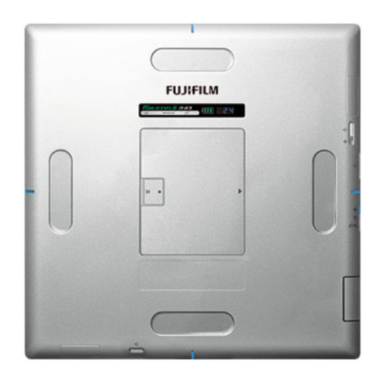
DIGITAL RADIOGRAPHY
(DR-ID 1200)
Operation Manual
2nd Edition : October 2014
897N120339A
This Operation Manual describes details on how to operate the FDR D-EVO
cautions to be observed when operating it. Please read the Operation Manual
thoroughly before actually operating the FDR D-EVO
Operation Manual" and other manuals for the related products.
After reading this manual, store it nearby the FDR D-EVO
it whenever necessary.
For Safe Operation
System
(Product Overview)
Basic Operation
Daily Inspection and
Maintenance
Appendix
Maintenance and
Inspection
II
II
along with "DR-ID 300CL
II
so that you can see
and
Advertisement
Table of Contents


Need help?
Do you have a question about the FDR D-EVO II and is the answer not in the manual?
Questions and answers