Table of Contents
Advertisement
FUJI COMPUTED RADIOGRAPHY
XG5000/XG2000
#20001 or Later
CR-IR 362
Service Manual
#50001 or Later
Document No.
011-207-09A
1st Edition -
Oct. 10, 2003
Revised Edition - Sep. 30, 2009
Printed in Japan
The relationship between mR (milliroentgen), which is the
unit of radiation, and μC/kg (micro-coulomb/kilogram),
which is the SI derived unit of radiation, is as follows.
1 mR = 0.258μC/kg
FDR is a trademark or a registered trademark of FUJIFILM Corporation.
<No part of this manual may be reproduced or transmitted.>
©
Copyright
2003-2009 by FUJIFILM Corporation. All rights reserved.
No part of this publication may be reproduced, stored in a retrieval
system, or transmitted in any form or by means, electronic,
mechanical, photocopying, recording or otherwise, without the prior
written permission of FUJIFILM Corporation.
Advertisement
Table of Contents

Related Manuals for FujiFilm XG5000


Summary of Contents for FujiFilm XG5000
- Page 1 μC/kg (micro-coulomb/kilogram), which is the SI derived unit of radiation, is as follows. 1 mR = 0.258μC/kg FDR is a trademark or a registered trademark of FUJIFILM Corporation. <No part of this manual may be reproduced or transmitted.> ©...
- Page 2 BLANK PAGE...
- Page 3 Used to indicate the matters that need attention during steps of the procedure. 4. The following conducts are prohibited without prior written approval of FUJIFILM Corporation: - Copy or transcribe a whole or part of the contents of this manual...
- Page 4 : A block gauge for use in inspection requires calibration. Servicing of the XG2000 - The servicing for the XG2000 is almost the same as that for the XG5000. Only the servicing operations specific to the XG2000 are described at the end of the respective service manuals.
-
Page 5: Table Of Contents
Contents Safety Precautions CR-IR 362 Service Manual - Contents Safety Precaution Safety Precautions ..............1 General Precautions ................1 Precautions Against Laser Radiation ..........2 Precautions on Patient Environment ..........2 Labels ..................3 Laser Precaution Labels ..............3 2.1.1 Laser Precaution Label Attachment Locations ..........3 2.1.2 List of CR-IR 362 Laser Precaution Labels ..........4 Other Labels ..................7... - Page 6 Contents Product Specifications Product Specifications 1. Specifications of Machine ............1 Product Code ..................1 Available IP Sizes and Types ............1 List of Optional Items ...............1 1.4 Product Specifications ..............2 Dimensions, Weight, and Center of Gravity ........2 Means for Moving and Fixing the Machine ........3 Environmental Conditions ...............3 1.8 Electrical Specifications ..............4 Installation Space and Servicing Space ..........4...
- Page 7 Contents Machine Description (MD) Machine Description (MD) 1. Machine Overview ............MD-1 Features ...................MD-1 1.2 System Configuration ...............MD-1 1.3 Overall Machine Configuration and Component Names ..MD-2 Machine Components ..............MD-4 1.4.1 Unit Locations ..................MD-4 1.4.2 Roller Locations and Conveyance Paths ..........MD-5 1.4.3 I/O Locations and Functional Descriptions........... MD-6 1.4.4 Board Locations .................
- Page 8 Contents Troubleshooting (MT) Troubleshooting (MT) Error Code Table .............MT-10 CR-IR 362 Service Manual 011-207-07E 02.19.2007 FM5097...
- Page 9 Contents Service Parts List(SP) Service Parts List(SP) How to Use Service Parts List ...............SP-1 FEED LOAD CONVEYOR 8 ...........SP-25 INDEX ....................SP-2 SIDE-POSITIONING CONVEYOR 1 ........SP-26 COVER 1 (#20001 or Later) ............SP-3 SIDE-POSITIONING CONVEYOR 2 ........SP-27 COVER 2 (#20001 or Later) ............SP-4 SIDE-POSITIONING CONVEYOR 3 ........SP-28 COVER 3 (#50001 or Later) ............SP-5 SIDE-POSITIONING CONVEYOR 4 ........SP-29...
- Page 10 Contents Service Parts List(SP) SUB SCANNING UNIT 1 ............SP-49 SUB SCANNING UNIT 2 ............SP-50 SUB SCANNING UNIT 3 ............SP-51 SUB SCANNING UNIT 4 ............SP-52 SUB SCANNING UNIT 5 ............SP-53 SUB SCANNING UNIT 6 ............SP-54 SUB SCANNING UNIT 7 ............SP-55 SUB SCANNING UNIT 8 ............SP-56 CONTROLLER 1 (#20001 or Later) ........SP-57 CONTROLLER 2 (#50001 or Later) ........SP-58 CONTROLLER 3 ..............SP-59...
- Page 11 Contents Preventive Maintenance (PM) Preventive Maintenance (PM) Preventive Maintenance Program ........PM-1 Cassette Set Unit ............PM-16 How To Use the Preventive Maintenance Volume ....PM-1 Removing the Feed/Load Conveyor Unit ....... PM-16 1.2 Notations of Intervals ..............PM-1 Cleaning the Rubber Rollers and Suction Cups ..... PM-17 Preventive Maintenance Program List ........
- Page 12 0.10 Contents Preventive Maintenance (PM) 10. Post-Reading Conveyor Unit ........PM-42 13. Erasure Conveyor Unit ..........PM-70 10.1 Removing the Retaining Member ........... PM-42 13.1 Removing the Lamp Assembly ..........PM-70 10.2 Removing the Post-Reading Conveyor Unit ......PM-42 13.2 Removing the Erasure Conveyor Unit ........
- Page 13 0.11 Contents Preventive Maintenance (PM) 18. Cleaning/Replacing the Air Filter (#20001 or later) ..PM-110 19. Securing the Machine ...........PM-111 19.1 Connecting the Cables ............PM-111 19.2 Securing the Machine ............PM-112 19.3 Checking for Improper Protective Grounding ....... PM-112 20. Checking the Image/Conveyance ........PM-113 21. Checking the Error Log ..........PM-113 22. Resetting the Erasure Lamp Lighting Time ....PM-113 23. Reset the number that pumps are used ......PM-114 0.11 CR-IR 362 Service Manual 011-207-09E...
- Page 14 0.12 Contents Installation (IN) Installation (IN) 1. Specifications of Machine ..........IN-1 Final Placement ..............IN-28 Securing the Cable ..............IN-28 2. Installation Work Flowchart ..........IN-2 Securing the Machine ...............IN-28 Preparation for Installation ..........IN-3 CL Installation Procedures ..........IN-29 Precautions Regarding Installation ..........IN-3 8. Installing RU Software ............. IN-29 3.1.1 Installation Site Requirements ...............
- Page 15 0.13 Contents Installation (IN) Appendix 1. Additional Protective Grounding .... Appx IN-1 Appendix 6. Procedures for Upgrading the XG2000 to the XG5000 ..... Appx IN-21 Appendix 2. Setting the Master CL ....... Appx IN-2 Removal and Replacement of Components ....Appx IN-21 Additionally Registering the Master CL Updating the RU Software Version ........Appx IN-22 (Procedures on the CL1) ...........Appx IN-2 Registering the RU (Procedures on the CL2) ....Appx IN-4...
- Page 16 0.14 Contents Performance Check (PC) Performance Check (PC) CR-IR 362 Performance Check List ........PC-1 Installation Information ................PC-1 Checklist ....................PC-1 0.14 CR-IR 362 Service Manual 011-207-07E 02.19.2007 FM5097...
- Page 17 Control Sheet Revision Pages affected Issue date Reason number 08.25.2003 New release (FM4098) All pages 11.15.2004 Corrections (FM4425) 05.09.2005 Corrections (FM4610) 4–15 10.02.2006 Change of Corporate Name and Corporate Logo (FM4977) 5, 7, 13 CR-IR 362 Service Manual 02.19.2007 Change of document number, corrections (FM5097) All pages 09.30.2008 Revision (FM5340)
-
Page 18: Safety Precautions
Safety Precaution- Safety Precautions Optical Parts When servicing the optical parts with the protective housings removed, be sure to turn OFF the power switch. Warnings and cautions regarding the procedures should be observed to avoid possible physical hazards and serious accidents that may occur during installation and ... -
Page 19: Precautions Against Laser Radiation
Safety Precaution- Precautions Against Laser Radiation Precautions on Patient Environment As indicated in the Certification and Indication Label attached on the lower left-hand Before the machine is installed, the supervisor at the machine installation site (the side cover of the machine, the machine complies with “Laser Products - Conformance hospital’s director) should check to see whether the machine is installed in the patient with IEC 60825-1, Am. -
Page 20: Labels
Safety Precaution- Labels Laser Precaution Labels 2.1.1 Laser Precaution Label Attachment Locations Below are illustrated the protective housings and attachment locations of laser precaution labels, as specified in "Laser Products - Conformance with IEC 60825-1, Am. 2 and IEC 60601-2-22; Final Guidance for Industry and FDA (Laser Notice No. 50) and NE60825-1 (Amendment 2).”... -
Page 21: List Of Cr-Ir 362 Laser Precaution Labels
Safety Precaution- 2.1.2 List of CR-IR 362 Laser Precaution Labels IEC/EN60825-1:2001 Class 3B Panel Label REFERENCE The laser caution label attached to the machine differs depending on its serial number. Shown below are the laser caution labels to be attached to the machines with the serial numbers of 21780 or earlier. - Page 22 Safety Precaution- IEC/EN60825-1: 2001 Class 3B Panel Label REFERENCE The laser caution label attached to the machine differs depending on its serial number. Shown below are the laser caution labels to be attached to the machines with the serial numbers of 21781 to 24649. HHS Certification and Identification Label ...
- Page 23 Safety Precaution- IEC/EN60825-1: 2001 Class 3B Panel Label REFERENCE The laser caution label attached to the machine differs depending on its serial number. Shown below are the laser caution labels to be attached to the machines with the serial numbers of 24650 or later and 50001 or later. HHS Certification and Identification Label ...
-
Page 24: Other Labels
Safety Precaution- Other Labels 2.2.1 Attachment Locations for Ratings Indication Label and Other Labels REFERENCE - The type of label is different depending on destinations and machine serial numbers. - There are some equipment on which manufacturer labels are not attached, depending on the serial numbers. - Page 25 Safety Precaution- Ratings Indication Labels of CR-IR 362 (machines with serial Ratings Indication Labels of CR-IR 362 (machines with serial numbers 21780 or those earlier than 21780) numbers 21781 to 24167) For use in Japan For use in Japan ...
- Page 26 Safety Precaution- Ratings Indication Labels of CR-IR 362 (Machines with serial Ratings Indication Labels of CR-IR 362 (Machines with serial numbers 24168 or those later than 24168) numbers 50001 or those later than 50001) For use in Japan ...
-
Page 27: Handling Instruction Labels And Attachment Locations
Safety Precaution- 2.2.2 Handling Instruction Labels and Attachment Feed/Load Conveyor Unit Locations Cassette Set Unit Side-Positioning Conveyor Unit Safety Precaution- CR-IR 362 Service Manual 011-207-08E 09.30.2008 FM5340... - Page 28 Safety Precaution- Post-reading conveyor unit Erasure Conveyor Unit Light-Collecting Guide (Front) Safety Precaution- CR-IR 362 Service Manual 011-207-08E 09.30.2008 FM5340...
- Page 29 Safety Precaution- Light-Collecting Guide (Back) Safety Precaution- CR-IR 362 Service Manual 011-207-08E 09.30.2008 FM5340...
- Page 30 Safety Precaution- Cassette Insertion Operation Labels Covers Safety Precaution- CR-IR 362 Service Manual 011-207-09E 09.30.2009 FM5539...
-
Page 31: Protective Housings Against Laser Exposure
Safety Precaution- Protective Housings Against Laser CLASSIFICATION Exposure 1. According to the type of protection against electrical shock Even when the protective housings are removed for servicing, laser beams will never leak out from the machine unless the optical path is intentionally changed. However, if CLASS 1 EQUIPMENT the optical path is changed inadvertently during optics-related procedures, the service 2. -
Page 32: Cautions On Electromagnetic Waves
5.1.1 Further information for IEC60601-1-2:2001 Model name XG5000/XG2000 is referred to as CR-IR 362 in this section. - Medical electrical equipment needs special precautions regarding EMC and needs to be installed and put into service according to the EMC information described as follows. - Page 33 Safety Precaution- Guidance and manufacturer’s declaration - electromagnetic immunity Guidance and manufacturer’s declaration - electromagnetic immunity The CR-IR 362 is intended for use in the electromagnetic environment specified below. The The CR-IR 362 is intended for use in the electromagnetic environment specified below. The customer or the user of the CR-IR 362 should assure that it is used in such an environment.
- Page 34 Safety Precaution- For European users: Recommended separation distances between Portable and mobile RF communications equipment and the CR-IR 362 Correspondence between applicable EMC standards and serial numbers of the The CR-IR 362 is intended for use in the electromagnetic environment in which machine radiated RF disturbances are controlled.
- Page 35 Safety Precaution- BLANK PAGE Safety Precaution- CR-IR 362 Service Manual 011-207-08E 09.30.2008 FM5340...
- Page 36 Safety Precaution- BLANK PAGE Safety Precaution- CR-IR 362 Service Manual 011-207-08E 09.30.2008 FM5340...
- Page 37 Control Sheet Revision Pages affected Issue date Reason number 08.25.2003 New release (FM4098) All pages 02.20.2004 Corrections (FM4181) 05.09.2005 Corrections (FM4610) All pages 02.19.2007 Change of document number (FM5097) All pages CR-IR 362 Service Manual 09.30.2009 Revision (FM5539) 1, 4 Product Specifications CR-IR 362 Service Manual 011-207-09E...
-
Page 38: Specifications Of Machine
24x30cm, 18x24cm Product code Item Qty. Remarks Metric settings ST-VI/ST-VN(standard type): 35x43cm, 35x35cm, FCR XG5000 (For outside Japan) CR IR 362 RU E #20001 or Later 24x30cm, 18x24cm Image reader machine main body CR-IR 362 HR-V(high resolution type): 24x30cm, 18x24cm... -
Page 39: Product Specifications
Product Specifications 1.4 Product Specifications Dimensions, Weight, and Center of Gravity Maximum Heat Generation Dimensions Standby: 340 W approx. W655×D740×H1480 (mm) Operating: 500 W approx. Noise Standby: 50 dB or less Operating: 60 dB or less Warm-up Time ... -
Page 40: Means For Moving And Fixing The Machine
Product Specifications Means for Moving and Fixing the Machine Environmental Conditions Moving Means Climate Conditions Double-wheel caster (variable-direction/no-brake) x4 Operating Fixing Means Temperature: 15 to 30°C Relative humidity: 40 to 80% RH - Adjustable foot x4, or retaining member x2 Atmospheric pressure: 70 to 1030 hPa Heat generation: 500 W approx. -
Page 41: Electrical Specifications
Product Specifications 1.8 Electrical Specifications Installation Space and Servicing Space Frequency Installation Space Single-phase, 50-60Hz, ±3% Input Voltage Single-phase, 120-240V~(AC)±10% Capacity 0.77 kVA Rated Amperage Single-phase, 120-240V~(AC)±10%, 50-60Hz : Power Consumption Maximum: 770 W Servicing Space ... -
Page 42: Disposal
Product Specifications 1.10 Disposal BLANK PAGE 1.10.1 Disposal of Machine When the machine is to be disposed of, the IMG17A/B board, which contains a battery, should be removed from the machine before its disposal. Be sure to return the removed IMG17A/B board to the Parts Center. 1.10.2 Disposal of IP Regarding the IP disposal, follow the instructions to dispose as laws are provided in... - Page 43 Product Specifications BLANK PAGE CR-IR 362 Service Manual Product Specifications 011-207-07E 02.19.2007 FM5097...
- Page 44 Product Specifications CR-IR 362 Service Manual Product Specifications 011-207-07E 02.19.2007 FM5097...
- Page 45 Control Sheet Revision Pages affected Issue date Reason number 08.25.2003 New release (FM4098) All pages 02.20.2004 Correction (FM4181) 02.19.2007 Change of document number, corrections (FM5097) All pages 09.30.2008 Revision (FM5340) 42, 57-83 CR-IR 362 Service Manual 09.30.2009 Revision (FM5539) 2, 13-91 Machine Description (MD) CR-IR 362 Service Manual 011-207-09E...
-
Page 46: Machine Overview
MD-1 Machine Overview 1.2 System Configuration The machine (CR-IR362) may be connected to a network to achieve various system configurations. Features Basic system configuration examples are described here. System Configuration Example (1) Features of the Machine The machine is connected to the CL via a network. The machine is network connectable via TCP/IP (100BASE-TX). A connection with the CL is established over Ethernet (100Base-TX). -
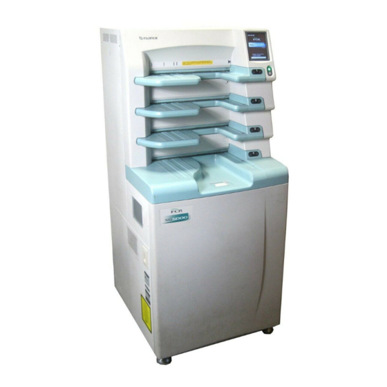
Page 47: Overall Machine Configuration And Component Names
MD-2 1.3 Overall Machine Configuration and Component Names External View of Machine MD-2 011-207-09E CR-IR 362 Service Manual 09.30.2009 FM5539... - Page 48 MD-3 Nomenclature and Functions Operation Panel Name Function Operation panel Operation panel for the RU main body. POWER lamp It is lit (in green) when the circuit breaker is pushed in the "I" position and power is turned ON. Since the circuit breaker remains in the ON state, the POWER lamp is always lit.
-
Page 49: Machine Components
MD-4 Machine Components 1.4.1 Unit Locations MD-4 011-207-07E CR-IR 362 Service Manual 02.19.2007 FM5097... -
Page 50: Roller Locations And Conveyance Paths
MD-5 1.4.2 Roller Locations and Conveyance Paths MD-5 011-207-07E CR-IR 362 Service Manual 02.19.2007 FM5097... -
Page 51: I/O Locations And Functional Descriptions
MD-6 1.4.3 I/O Locations and Functional Descriptions A list of sensor and barcode reader names and functions is presented below. Cassette set unit I/O Locations: Cassette Set Unit and Feed/Load Conveyor Unit Symbol Name Type Function Locations of the sensors and barcode reader are illustrated below. SA1, 7, 13, 19 Cassette ejection PI (5mm) - Page 52 MD-7 I/O Locations: Side-Positioning Conveyor Unit, Subscanning A list of sensor and barcode reader names and functions is presented below. Unit, and Post-Reading Conveyor Unit Side-positioning conveyor unit Locations of the sensors and barcode reader are illustrated below. Symbol Name Type...
- Page 53 MD-8 I/O Locations: Erasure Conveyor Unit and Housing A list of sensor and thermistor names and function is presented below. Erasure conveyor unit Locations of the sensors and thermistor are illustrated below. Symbol Name Type Function Post-reading conveyance PI (19mm) Detects that an IP being standby IP sensor...
- Page 54 MD-9 I/O Locations: Cassette Set Unit and Feed/Load Conveyor Unit A list of motor, clutch, solenoid, pump, and solenoid valve names and functions is presented below. Locations of the motors, clutches, solenoids, pumps, and solenoid valves are illustrated below. ...
- Page 55 MD-10 I/O Locations: Side-Positioning Conveyor Unit, Subscanning A list of motor names and functions is presented below. Unit, and Post-Reading Conveyor Unit Side-positioning conveyor unit Locations of the motors are illustrated below. Symbol Name Type Function Side-positioning motor Pulse motor Drives the side-positioning mechanism...
- Page 56 MD-11 I/O Locations: Erasure Conveyor Unit and Housing A list of motor, solenoid, and fan names and functions is presented below. Erasure conveyor unit Locations of the motors, solenoids, and fans are illustrated below. Symbol Name Type Function IP transport motor Pulse motor Transports an IP.
-
Page 57: Board Locations
MD-12 1.4.4 Board Locations MD-12 011-207-07E CR-IR 362 Service Manual 02.19.2007 FM5097... -
Page 58: System Block Diagram
MD-13 1.5 System Block Diagram Power Supply System (#20001 or Later) Power supply unit +5V(A) +5V(S) +15V(D) +15V(F) -15V(H) PSU17A +12V(K) +24V(B) +5V(C) +24V(E) +24V(B) +15V(G) +24V(J) CN25 Driver board Driver board Inverter board DRV17A DRV17B INV17A +24V(B) +24V(B) M(DC) LAMP1, 2, 3 CN20 Sensor board Sensor board... - Page 59 MD-14 Signal System (#20001 or Later) Power supply unit PSU17A +24V (B) Driver board Driver board DRV17A Driver DRV17B Inverter board Driver circuit INV17A circuit Inverter CN1 CN2 CN21 CN22 circuit M (DC) LAMP1, 2, 3 Sensor board CN5 CN6 CN7 CN8 Sensor board Inverter board SNS17B...
- Page 60 MD-15 Power Supply System (#50001 or Later) Power supply board +5V(S) +15V(D) +15V(F) -15V(H) (A-3) PSU29A +24V +24V +24V (A-2) (B-2) (A-1) (B-3) +15V(G) Driver board CN25 Driver board DRV17A DRV17B Erasure board +24V(B-2) +24V(B-2) ERS23A M(DC) M(DC) M(DC) Inverter board Inverter board INV26A...
- Page 61 MD-16 Signal System (#50001 or Later) Power supply board PSU29A Driver board Driver board Driver Driver DRV17A DRV17B circuit circuit Erasure board ERS23A CN21 CN22 CN81 M(DC) M(DC) M(DC) Inverter board Inverter board INV26A INV26A THB1 LAMPB4, 6 LAMPB3, 5 Sensor board CN5 CN6 CN7 CN8 Sensor board...
- Page 65 Control Sheet Revision Pages affected Issue date Reason number 08.25.2003 Corrections (FM4098) All pages 10.10.2003 Corrections (FM4160) 2-5, 8, 14, 16, 25, 27-30, 33-38, 44-46, 50-53, 58, 59, 59.1, 59.2, 60-73, 75, 76, 7 8 , 7 9 , 8 1 - 8 3 , 8 5 , 8 6 , 8 8 - 11 3 , CR-IR 362 Service Manual 113.1, 113.2, 114-118, 120-122, 124-133, 135, 136, 138-142, 145, 148, 151, 154,...
- Page 66 MT-10 Error Code Table Error Analysis Error Name Occurrence Condition Code Flow During bootup, when the file is loaded from the FLASH ROM on the IMG17A/IMG17B board into the SD RAM, error 10001 File open error (1) is detected for the file residing in the FLASH ROM. Alternatively, an error is detected for the file residing in the SD {MT:18.} RAM.
- Page 67 MT-11 Error Analysis Error Name Occurrence Condition Code Flow During bootup, when the file is loaded from the FLASH ROM on the IMG17A/IMG17B board into the SD RAM, error 10014 File close error (2) is detected for the file residing in the FLASH ROM. Alternatively, an error is detected for the file residing in the SD {MT:18.} RAM.
- Page 68 MT-12 Error Analysis Error Name Occurrence Condition Code Flow Image processing initialization During bootup or during routine processing, when an attempt is made to initialize the image processing section of 10100 the IMG board, 12101 error is detected. {MT:18.} error Because it is detected three or more times, fatal error results.
- Page 69 MT-13 Error Analysis Error Name Occurrence Condition Code Flow - During bootup or during routine processing, because the fuse (H011 on the SCN17A/SCT17B board) is blown, ± 15V is not supplied to the SCN17A/SCT17B board, and the photomultiplier (PMT/PMR), start-point detection (SYN), laser (LDD), and SCN board (PLL) functions are disabled.
- Page 70 MT-14 Error Analysis Error Name Occurrence Condition Code Flow During bootup, error for the polygon lock signal (PONL, POKL) is detected so that the polygonal mirror function is 10261 Polygon rotation error (1) disabled. The start-point detection (SYN) and leading-edge detection (SED) functions are also disabled (detail code: {MT:5.8} 903403, 003400, 902403).
- Page 71 MT-15 Error Analysis Error Name Occurrence Condition Code Flow Side-positioning unit IP During routine processing, the IP transport motor (MC3) is driven for IP side-positioning conveyance, but the side- 10346 positioning IP sensor (SC3) does not transition to CLOSE within the specified period of time. {MT:4.1} conveyance error Subscanning unit IP leading-edge...
- Page 72 MT-16 Error Analysis Error Name Occurrence Condition Code Flow Switchback unit IP conveyance During bootup/routine processing, the branch path changeover guide drive solenoid (SOLE1) and IP transport motor 10354 (ME1) are driven for IP switchback operation, but the CLOSE state of the post-reading conveyance standby IP {MT:4.5} error (1) sensor (SE1) is detected.
- Page 73 MT-17 Error Analysis Error Name Occurrence Condition Code Flow Post-erasure path guide status During bootup/routine processing, the IP transport motor (ME1, MB1, MB2) is driven to convey the IP to the cassette 10362 after the IP is erased, and the pre-BCR IP sensor (SB5) transitions to CLOSE; however, the IP feed/load sensor {MT:4.6} error (2) (SB1/2/3/4) for other than the shelf of interest transitions to CLOSE.
- Page 74 MT-18 Error Analysis Error Name Occurrence Condition Code Flow Side-positioning unit grip HP During bootup/M-Utility, the grip release motor (MC2) is driven to perform grip home-positioning of the side- 10374 positioning conveyor unit; however, the OPEN or CLOSE of the grip release HP sensor (SC2) is not detected. After {MT:4.8} detection error two retries are executed, this is not detected, so that the system goes down.
- Page 75 MT-19 Error Analysis Error Name Occurrence Condition Code Flow During bootup/M-Utility, the IP stopper drive motor (MZ4) is driven to perform home-positioning of the IP stopper; 10403 IP stopper HP detection error however, the OPEN or CLOSE of the IP stopper HP sensor (SZ5) is not detected. After two retries are executed, {MT:4.14} this is not detected, so that the system goes down.
- Page 76 MT-20 Error Analysis Error Name Occurrence Condition Code Flow For the correction processing during bootup/at the end of reading, the grip drive motor (MZ2) is driven to correct Driving-shaft grip correction error the grip speed of the driving shaft for the GR type; however, the driving-side grip release HP sensor (SZ2) does not 10416 transition to OPEN within the specified period of time.
- Page 77 MT-21 Error Analysis Error Name Occurrence Condition Code Flow During bootup, the pre-convergence IP sensor (SB6) and side-positioning entrance IP sensor (SG1) are CLOSE, 10422 IP-initialization IP search error (3) and the post-reading conveyance standby IP sensor (SE1) or switchback standby IP sensor (SE2) is CLOSE for the {MT:4.16} remaining IP search processing.
- Page 78 MT-22 Error Analysis Error Name Occurrence Condition Code Flow During M-Utility, the dust removal motor (MZ3) is driven (clockwise) to perform dust removal operation; however, the 10435 Dust removal operation error (1) {MT:4.17} dust removal HP sensor (SZ4) does not transition to CLOSE within the specified period of time. During M-Utility, the dust removal motor (MZ3) is driven (clockwise) to perform dust removal operation;...
- Page 79 MT-23 Error Analysis Error Name Occurrence Condition Code Flow Initialization feed path IP During bootup, the IP transport motor (MB1, MB2) is driven to perform the remaining IP search processing; however, 10443 the pre-BCR IP sensor (SB5) does not transition to OPEN within the specified period of time. {MT:4.18} conveyance error (1) (UP) Initialization feed path IP...
- Page 80 MT-24 Error Analysis Error Name Occurrence Condition Code Flow During bootup, the IP transport motor (MC3) and subscanning motor (MZ1) are driven to perform the remaining IP Initialization side-positioning unit search processing; however, the side-positioning entrance IP sensor (SG1) does not transition to CLOSE within the 10450 {MT:4.19} specified period of time.
- Page 81 MT-25 Error Analysis Error Name Occurrence Condition Code Flow Initialization subscanning unit IP During bootup, the IP transport motor (MC3) is driven to perform the remaining IP search processing; however, the 10458 post-reading conveyance IP sensor (SD2) does not transition to OPEN within the specified period of time. {MT:4.35} ejection error (2) Initialization IP position...
- Page 82 MT-26 Error Analysis Error Name Occurrence Condition Code Flow <User operation> After the cassette is loaded, the cassette is pulled out immediately. <Occurrence condition> 11320 Cassette setting status error (1) {MT:4.21} During routine processing/M-Utility, the cassette hold solenoid (SOLA1/2/3/4) is turned OFF to hold the cassette, and the cassette hold sensor (SA3/9/15/21) detects the OPEN state;...
- Page 83 MT-27 Error Analysis Error Name Occurrence Condition Code Flow Feed/load unit entrance IP feed During routine processing/M-Utility/abnormality processing, an attempt is made to convey the IP from the cassette 11330 to the feed/load conveyor unit; however, the IP feed/load sensor (SB1/2/3/4) does not transition to CLOSE. Though {MT:4.22} retry the retries (twice) for the IP suction are executed, the IP is not transported to the IP feed/load sensor.
- Page 84 MT-28 Error Analysis Error Name Occurrence Condition Code Flow During routine processing/M-Utility, the IP size detected by the machine is compared with the IP barcode information; however, error is detected in the barcode information. 11341 IP size detection error (2) {MT:4.40} If the IP is conveyed with the inch/metric sensor (SA6/SA12/SA18/SA24) damaged, the IP is conveyed to the IP bar code reader (BCR1) of the side positioning conveyer unit and thereafter ejected to the cassette.
- Page 85 MT-29 Error Analysis Error Name Occurrence Condition Code Flow <User operation> Empty the largest cassette and The IP size was unknown or the ejection destination cassette was not found during bootup. 11498 <Action> insert the cassette Insert an empty cassette. A remaining IP that could not be returned as an unprocessed IP was detected at a position behind the subscanning 11499 IP reading suspended...
- Page 86 MT-30 Error Analysis Error Name Occurrence Condition Code Flow During bootup, it is detected that temperature control of the erasure unit is disabled due to temperature thermistor Thermistor failure detection 11731 (THE1) error. {MT:6.5} (during erasure initialization) Lamp unlit detection (during During bootup, the erasure lamps are turned on to check their lighting, but a single center lamp (socket L3) of the 11737 five erasure lamps is unlit.
- Page 87 MT-31 Error Analysis Error Name Occurrence Condition Code Flow During routine processing, a timeout of the frame clock lock (information indicative of the leading edge of the image 12148 Image frame clock timeout {MT:6.1} data) sent from the SCN17A/SCT17B board is detected by the sub-CPU. (30 seconds) An error is detected for the pixel clock from the sub-CPU of the IMG17A/IMG17B board to the SCN17A/SCT17B Image processing pixel clock board.
- Page 88 MT-32 Error Analysis Error Name Occurrence Condition Code Flow 12202 Leading-edge detection error During bootup, only error for the leading-edge detection signal (SED1L) is detected. {MT:5.14} During bootup, an SCN board diagnostic error (no main-scan sync signal is generated) associated with polygon 12203 SCN sync signal error {MT:5.8}...
- Page 89 MT-33 Error Analysis Error Name Occurrence Condition Code Flow 12225 Reading status error During routine processing, error is detected for the VSYNC signal on the SCN17A/SCT17B board. {MT:18.} 12226 Operation line status error During routine processing, error is detected for the SEDTM/FCLKTM signal on the SCN17A/SCT17B board. {MT:18.} During bootup or during routine processing, error is detected for the PLL function, polygon rotation function, start- 12241...
- Page 90 MT-34 Error Analysis Error Name Occurrence Condition Code Flow During bootup, only error for the lock signal (POKL, PONL) from the polygonal mirror (POL) is detected (detail code: 12263 Polygon rotation error (3) 002001). {MT:5.8} If error for the SEDTM or FCLKTM signal on the SCN17A/SCT17B board is detected, the detail code is 002003. During bootup or during routine processing, error for the signals (PONL, POKL, PINDXL) from the polygonal mirror and the SEDTM signal on the SCN17A/SCT17B board is detected (detail code: 001002).
- Page 91 MT-35 Error Analysis Error Name Occurrence Condition Code Flow Scanning optics unit board error During bootup, the laser (LDD), start-point detection (SYN), and leading-edge detection (SED) functions are 12283 disabled due to laser failure or disconnected connector. {MT:5.15} during bootup 12284 LD monitor value error warning During IP reading, the laser drive current value (LDIF) becomes more than 1.4 times the factory default value.
- Page 92 MT-36 Error Analysis Error Name Occurrence Condition Code Flow During routine processing, because scanner-related error is detected, the IP is returned to the cassette and scanner 12298 Scanner retry error {MT:5.11} initialization is performed, with a retry made for routine processing. 12299 Error for scanner, etc.
- Page 93 MT-37 Error Analysis Error Name Occurrence Condition Code Flow During routine processing/M-Utility/abnormality processing, the IP leak valve (SVA1/2/3/4) is driven to convey the 12331 IP-feed air leak warning IP from the cassette to the feed/load conveyor unit, and the IP suction pump (PA1/2/3/4) is stopped; however, the {MT:4.41} suction sensor (SA5/11/17/23) does not transition to CLOSE within the specified period of time.
- Page 94 MT-38 Error Analysis Error Name Occurrence Condition Code Flow FFM motor rpm out of During routine processing except for secondary erasure, the motor rotation W.F. error of the subscanning motor (MZ1) 12348 for the W.F. monitoring operation is detected. {MT:4.29} specification During bootup/routine processing, the IP transport motor (MD2, ME1) is driven to convey the IP to the erasure 12350...
- Page 95 MT-39 Error Analysis Error Name Occurrence Condition Code Flow During bootup/routine processing/M-Utility, the convergence path changeover guide drive motor (MB3) is driven to 12370 Path guide HP detection retry (2) perform home-positioning of the path changeover guide (feed/load conveyor unit); however, the path changeover {MT:4.7} shelf sensor (SB7/8/9) does not transition to CLOSE within the specified period of time, thus resulting in a retry.
- Page 96 MT-40 Error Analysis Error Name Occurrence Condition Code Flow Side-positioning unit grip HP During bootup/routine processing/M-Utility, the grip release motor (MC2) is driven to perform grip operation of the 12377 side-positioning conveyor unit; however, the grip release HP sensor (SC2) does not transition to CLOSE, so that {MT:4.8} detection warning home-positioning is performed.
- Page 97 MT-41 Error Analysis Error Name Occurrence Condition Code Flow Erasure unit grip HP detection During bootup/M-Utility, the grip release motor (ME3) is driven to convey the IP after IP erasure; however, the grip 12385 release HP sensor (SE5) does not transition to CLOSE, so that home-positioning is performed. {MT:4.10} warning Side-positioning unit side-...
- Page 98 MT-42 Error Analysis Error Name Occurrence Condition Code Flow Erasure unit side-positioning During bootup/routine processing/M-Utility, the side-positioning motor (ME2) is driven to perform side-positioning 12392 mechanism home-positioning in the erasure conveyor unit; however, the erasure side-positioning mechanism HP {MT:4.33} mechanism HP detection retry (3) sensor (SE4) does not transition to OPEN within the specified period of time, thus resulting in a retry.
- Page 99 MT-43 Error Analysis Error Name Occurrence Condition Code Flow Cleaning guide grip operation During bootup/routine processing/M-Utility, the cleaning guide drive motor (MC4) is driven to grip the cleaning guide 12401 (guide-down); however, the cleaning guide HP sensor (SC4) does not transition to OPEN. {MT:4.13} detection warning Cleaning guide HP detection...
- Page 100 MT-44 Error Analysis Error Name Occurrence Condition Code Flow Driving-shaft grip speed correction For the correction processing during bootup/at the end of reading, the grip speed of the driving shaft is corrected; 12417 however, the driving-side grip release HP sensor (SZ2) does not transition to OPEN within the specified period of {MT:4.15} value warning time, thus resulting in a retry for grip speed correction.
- Page 101 MT-45 Error Analysis Error Name Occurrence Condition Code Flow Although the SET command was transmitted from the RU during routine processing, a signal other than OK was 12523 SET command CL receiving error received as a response from the CL. After the processed IP returns to a cassette, the cassette is ejected so that the associated message appears on the RU panel.
- Page 102 MT-46 Error Analysis Error Name Occurrence Condition Code Flow Back-side photomultiplier control During bootup and routine processing, only error for the PMR analog power supply signal (+15VOKH, +15VOKL) is 12651 detected (detail code: 008100). Note that if the HV is OFF, the detail code is 008000. {MT:5.13} board error (1) Back-side photomultiplier control...
- Page 103 MT-47 Error Analysis Error Name Occurrence Condition Code Flow 12705 LCD bus error During bootup, the CPU91A board detects a bus error for the LCD panel. {MT:18.} High-temperature error detection During bootup, the temperature thermistor (THE1) detects high-temperature error. 12733 {MT:6.4} (during erasure initialization) Single lamp unlit detection (during...
- Page 104 MT-48 Error Analysis Error Name Occurrence Condition Code Flow 12810 Power supply A021 error During bootup and during routine processing, it is detected that the "A021" fuse (F1) on the SNS17B board is blown. {MT:9.} 12811 Power supply A031 error During bootup and during routine processing, it is detected that the "A031"...
- Page 105 MT-49 Error Analysis Error Name Occurrence Condition Code Flow During bootup and during routine processing, it is detected that the "B101" fuse (F10) on the DRV17A board is 12830 Power supply B101 error {MT:9.} blown. During bootup and during routine processing, it is detected that the "B111" fuse (F11) on the DRV17A board is 12831 Power supply B111 error {MT:9.}...
- Page 106 MT-50 Error Analysis Error Name Occurrence Condition Code Flow During bootup and during routine processing, it is detected that the "B251" fuse (F10) on the DRV17B board is 12851 Power supply B251 error {MT:9.} blown. During bootup and during routine processing, it is detected that the "B261" fuse (F11) on the DRV17B board is 12852 Power supply B261 error {MT:9.}...
- Page 107 MT-51 Error Analysis Error Name Occurrence Condition Code Flow During bootup and during routine processing, it is detected that the "G041" fuse (F1) on the SCN17A/SCT17B board 12874 Power supply G041 error {MT:9.} is blown. During bootup and during routine processing, it is detected that the "G051" fuse (F7) on the SCN17A/SCT17B board 12875 Power supply G051 error {MT:9.}...
- Page 108 MT-52 Error Analysis Error Name Occurrence Condition Code Flow During bootup or during routine processing, the range of variations in the main-scan interval is beyond the upper or lower limit of the error decision value parameter. <User operation> 13260 Main-scan interval warning When vibration is applied to the machine from the outside while the adjuster bolt is not lowered, the vibration is transmitted to the scanning optics unit and logged.
- Page 109 MT-53 Error Analysis Error Name Occurrence Condition Code Flow CL communication failure During bootup or during routine processing, because the communication between the CL and RU is broken, the 13521 connection is suspended and initialization of communication between the CL and RU is performed again. detected The CL was too late receiving the image data sent from the RU, so that the image was retransmitted from the RU.
- Page 110 MT-54 Error Analysis Error Name Occurrence Condition Code Flow 13703 Flash ROM read/write error An error is detected for the flash ROM read/write test in MUTL: Board Check. {MT:18.} 13704 CPU91A interrupt error An error is detected for the CPU91A interrupt test in MUTL: Board Check. {MT:18.} 13705 Network register error...
- Page 111 The error code table is stored as an access file (.mdb) in the installation CD-ROM of the RU software. The following example shows a path on which the CR-IR 363 error code table is stored when the installation CD-ROM of the RU software V2.4 is inserted into the D drive: D:\FujiFilm\FCR\CR-IR363\2.4\common\TOOL\EcodeMan.mdb.
- Page 113 Control Sheet Issue date Revision number Reason Pages affected 07.22.2003 New relese All pages 08.20.2003 Corrections (FM 4098) All pages 02.20.2004 Corrections (FM 4181) 2-77 10.08.2004 Corrections (FM 4425) 6, 12, 15, 17, 24, 34, 35, 37, 38, 41-43, CR-IR362 Service Manual 47, 48, 50, 52-75 05.09.2005 Corrections (FM 4610)
- Page 114 SP-1 How to Use Service ■ Recommended quantities of spare ○ For software Character Significance parts The alphabet denotes a difference in the Consumable parts or parts Parts List specifications. Parts differing in the suffix that will be replaced at short It is recommended as a rough guide to hold are not compatible with each other.
- Page 115 SP-2 INDEX INDEX INDEX INDEX INDEX INDEX INDEX ● カバー ● フレーム ● カセッテセット部 ● 副走査部 ● 制御部 ●ケーブル COVER FRAME CASSETTE SET UNIT SUB SCANNING UNIT CONTROLLER CABLE INDEX INDEX INDEX INDEX INDEX INDEX ● フィードロード搬送部 ● 幅寄搬送部 ● 後搬送部 ●...
- Page 116 SP-3 カバー 1(#20001 以降) カバー 1(#20001 以降) COVER 1 (#20001 or Later) COVER 1 (#20001 or Later) RANK REF. PART NO. PART NAME REMARKS SERIAL NO. REFER TO 343N0048 フック Hook 350Y1694 カバー Cover {MC:3.1} 350Y1709 カバー Cover For PHILIPS {MC:3.1} 350Y1703 カバー...
- Page 117 SP-4 カバー 2(#20001 以降) カバー 2(#20001 以降) COVER 2 (#20001 or Later) COVER 2 (#20001 or Later) RANK REF. PART NO. PART NAME REMARKS SERIAL NO. REFER TO 350Y1680 Cover カバー {MC:3.1} 350Y1682 カバー Cover {MC:3.1} 350N2059A/B/C カバー Cover 350Y1681 カバー...
- Page 118 SP-5 カバー 3(#50001 以降) カバー 3(#50001 以降) COVER 3 (#50001 or Later) COVER 3 (#50001 or Later) RANK REF. PART NO. PART NAME REMARKS SERIAL NO. REFER TO 350Y101188 カバー Cover {MC:3.1} 350Y101279 カバー Cover For PHILIPS {MC:3.1} For CR-IR362 350Y101280 カバー...
- Page 119 SP-6 カバー 4(#50001 以降) カバー 4(#50001 以降) COVER 4 (#50001 or Later) COVER 4 (#50001 or Later) RANK REF. PART NO. PART NAME REMARKS SERIAL NO. REFER TO 350Y101183A Cover カバー {MC:3.1} 350Y101144 カバー Cover {MC:3.1} 350Y101177A カバー Cover {MC:3.1} 350N100941A Cover カバー...
- Page 120 SP-7 フレーム 1 フレーム 1 FRAME 1 FRAME 1 RANK REF. PART NO. PART NAME REMARKS SERIAL NO. REFER TO 367N1008 キャスタ Caster - 367S1078 キャスタ Caster - 367N1006 キャスタ Caster - 367S2059 脚 Adjuster Assembly - 356N9404C ブラケット Bracket -...
- Page 121 SP-8 フレーム 2(#20001 以降) フレーム 2(#20001 以降) FRAME 2 (#20001 or Later) FRAME 2 (#20001 or Later) RANK REF. PART NO. PART NAME REMARKS SERIAL NO. REFER TO Compression Coil 388N1211A 圧縮コイルバネ L ≒ 25mm {MC:4.13} Spring 319N4037B 軸 Shaft {MC:4.13} 363Y0477 ガイド板...
- Page 122 SP-9 フレーム 3(#50001 以降) フレーム 3(#50001 以降) FRAME 3 (#50001 or Later) FRAME 3 (#50001 or Later) RANK REF. PART NO. PART NAME REMARKS SERIAL NO. REFER TO Compression Coil 388N1211A 圧縮コイルバネ L ≒ 25mm {MC:4.13} Spring 319N101426 軸 Shaft {MC:4.13} 363Y0477 ガイド板...
- Page 123 SP-10 フレーム 4 フレーム 4 FRAME 4 FRAME 4 RANK REF. PART NO. PART NAME REMARKS SERIAL NO. REFER TO 375N0099 Seal シール - 347N1841B スペーサ Spacer - #20001 or 356N9222B ブラケット Bracket - later 356N9187A ブラケット Bracket - #20001 or 350N2725D カバー...
- Page 124 SP-11 カセッテセット部 1(#20001 以降) カセッテセット部 1(#20001 以降) CASSETTE SET UNIT 1 (#20001 or Later) CASSETTE SET UNIT 1 (#20001 or Later) RANK REF. PART NO. PART NAME QTY. REMARKS SERIAL NO. REFER TO 146S0029/A ホトインタラプタ Photo Sensor SA6, 12, 18, 24 {MC:5.27} 146S0029/A ホトインタラプタ...
- Page 125 SP-12 カセッテセット部 2(#50001 以降) カセッテセット部 2(#50001 以降) CASSETTE SET UNIT 2 (#50001 or Later) CASSETTE SET UNIT 2 (#50001 or Later) RANK REF. PART NO. PART NAME QTY. REMARKS SERIAL NO. REFER TO 146S0029/A ホトインタラプタ Photo Sensor SA6, 12, 18, 24 {MC:5.27} 146S0029/A ホトインタラプタ...
- Page 126 SP-13 カセッテセット部 3(#20001 以降) カセッテセット部 3(#20001 以降) CASSETTE SET UNIT 3 (#20001 or Later) CASSETTE SET UNIT 3 (#20001 or Later) RANK REF. PART NO. PART NAME QTY. REMARKS SERIAL NO. REFER TO 128S0392 スイッチ Switch SA5, 11, 17, 23 {MC:5.20} 133Y1031A/B 電動ポンプ...
- Page 127 SP-14 カセッテセット部 4(#50001 以降) カセッテセット部 4(#50001 以降) CASSETTE SET UNIT 4 (#50001 or Later) CASSETTE SET UNIT 4 (#50001 or Later) RANK REF. PART NO. PART NAME QTY. REMARKS SERIAL NO. REFER TO 128Y0331 スイッチ Switch SA5, 11, 17, 23 {MC:5.20} 133Y2034C 電動ポンプ...
- Page 128 SP-15 カセッテセット部 5 カセッテセット部 5 CASSETTE SET UNIT 5 CASSETTE SET UNIT 5 RANK REF. PART NO. PART NAME QTY. REMARKS SERIAL NO. REFER TO 315N0011 止め輪 Snap Ring {MC:5.22} 316S0146 止め具 Clamp {MC:5.21} 319N3918 軸 Shaft {MC:5.33} 322N0037D すべり軸受 Plain Bearing {MC:5.32} 322SF149...
- Page 129 SP-16 カセッテセット部 6 カセッテセット部 6 CASSETTE SET UNIT 6 CASSETTE SET UNIT 6 RANK REF. PART NO. PART NAME QTY. REMARKS SERIAL NO. REFER TO 106Y0005B/C 電磁クラッチ Electromagnetic Clutch CLA1, 2, 3, 4 {MC:5.16} 118SX167/A パルスモータ Stepping Motor MA1, 2, 3, 4 {MC:5.11} 322N0038A すべり軸受...
- Page 130 SP-17 カセッテセット部 7 カセッテセット部 7 CASSETTE SET UNIT 7 CASSETTE SET UNIT 7 RANK REF. PART NO. PART NAME QTY. REMARKS SERIAL NO. REFER TO 319N3962 軸 Shaft {MC:5.39} 322SY066 すべり軸受 Plain Bearing {MC:5.39} 332N0521C ストッパ Stopper {MC:5.39} 332N0522E ストッパ Stopper {MC:5.26} 332N0523E...
- Page 131 SP-18 フィードロード搬送部 1 フィードロード搬送部 1 FEED LOAD CONVEYOR 1 FEED LOAD CONVEYOR 1 RANK REF. PART NO. PART NAME QTY. REMARKS SERIAL NO. REFER TO 356N8928B ブラケット Bracket {MC:6.12} 356N8929B ブラケット Bracket {MC:6.11} 327N1123601B 平歯車 Spur Gear {MC:6.6} 339N0022A ハンドル Handle {MC:6.6} 356N8931A...
- Page 132 SP-19 フィードロード搬送部 2 フィードロード搬送部 2 FEED LOAD CONVEYOR 2 FEED LOAD CONVEYOR 2 RANK REF. PART NO. PART NAME QTY. REMARKS SERIAL NO. REFER TO 327N1123601B 平歯車 Spur Gear {MC:6.13} 327N1122421 平歯車 Spur Gear {MC:6.13} 327N1127201A 平歯車 Spur Gear {MC:6.13} 327N0188A 平歯車...
- Page 133 SP-20 フィードロード搬送部 3 フィードロード搬送部 3 FEED LOAD CONVEYOR 3 FEED LOAD CONVEYOR 3 RANK REF. PART NO. PART NAME QTY. REMARKS SERIAL NO. REFER TO 356N9133A ブラケット Bracket 356N9135 ブラケット Bracket 146S0029/A ホトインタラプタ Photo Sensor SB7, 8, 9 {MC:6.3} 356N9188 ブラケット...
- Page 134 SP-21 フィードロード搬送部 4 フィードロード搬送部 4 FEED LOAD CONVEYOR 4 FEED LOAD CONVEYOR 4 RANK REF. PART NO. PART NAME QTY. REMARKS SERIAL NO. REFER TO 327N1121608A 平歯車 Spur Gear {MC:6.23} 388N2517 引張りコイルバネ Extension Spring L ≒ 90mm {MC:6.23} #20001 or 321Y100002 ころがり軸受アセンブリ...
- Page 135 SP-22 フィードロード搬送部 5 フィードロード搬送部 5 FEED LOAD CONVEYOR 5 FEED LOAD CONVEYOR 5 RANK REF. PART NO. PART NAME QTY. REMARKS SERIAL NO. REFER TO 388N2518 引張りコイルバネ Extension Spring L ≒ 42mm {MC:6.25} 341N1049 アーム {MC:6.25} 322N0032 軸受 Bearing {MC:6.25} 322N2001A すべり軸受...
- Page 136 SP-23 フィードロード搬送部 6 フィードロード搬送部 6 FEED LOAD CONVEYOR 6 FEED LOAD CONVEYOR 6 RANK REF. PART NO. PART NAME QTY. REMARKS SERIAL NO. REFER TO 363Y0450 ガイド Guide 334N3577A ゴムローラ Rubber Roller {MC:6.29} 334N3578A ゴムローラ Rubber Roller {MC:6.29} #20001 or 321Y100002 ころがり軸受アセンブリ...
- Page 137 SP-24 フィードロード搬送部 7 フィードロード搬送部 7 FEED LOAD CONVEYOR 7 FEED LOAD CONVEYOR 7 RANK REF. PART NO. PART NAME QTY. REMARKS SERIAL NO. REFER TO 327N1121608A 平歯車 Spur Gear {MC:6.32} 388N2517 引張りコイルバネ Extension Spring L ≒ 90mm {MC:6.32} #20001 or 321Y100002 ころがり軸受アセンブリ...
- Page 138 SP-25 フィードロード搬送部 8 フィードロード搬送部 8 FEED LOAD CONVEYOR 8 FEED LOAD CONVEYOR 8 RANK REF. PART NO. PART NAME QTY. REMARKS SERIAL NO. REFER TO 388N2520 引張りコイルバネ Extension Spring L ≒ 80mm {MC:6.33} 341N1050B アーム {MC:6.33} 322N2002 すべり軸受 Plain Bearing {MC:6.33} 363Y0455B/C ガイド...
- Page 139 SP-26 幅寄搬送部 1 幅寄搬送部 1 SIDE-POSITIONING CONVEYOR 1 SIDE-POSITIONING CONVEYOR 1 RANK REF. PART NO. PART NAME QTY. REMARKS SERIAL NO. REFER TO 334Y2244A 樹脂ローラアセンブリ Resin Roller Assembly {MC:7.22} 356N8932B ブラケット Bracket {MC:7.22} 356N9166D ブラケット Bracket {MC:7.22} 356N9230A ブラケット Bracket {MC:7.22} 334N3580B 樹脂ローラ...
- Page 140 SP-27 幅寄搬送部 2 幅寄搬送部 2 SIDE-POSITIONING CONVEYOR 2 SIDE-POSITIONING CONVEYOR 2 RANK REF. PART NO. PART NAME QTY. REMARKS SERIAL NO. REFER TO 113Y1466 ボードアセンブリ Board Assembly {MC:7.5} 146N0016B フォトインタラプタ Photo Sensor {MC:7.5} 118SX167/A パルスモータ Stepping Motor {MC:7.9} 146S0029/A ホトインタラプタ Photo Sensor {MC:7.4} 319N3940A...
- Page 141 SP-28 幅寄搬送部 3 幅寄搬送部 3 SIDE-POSITIONING CONVEYOR 3 SIDE-POSITIONING CONVEYOR 3 RANK REF. PART NO. PART NAME QTY. REMARKS SERIAL NO. REFER TO 118SX167/A パルスモータ Stepping Motor {MC:7.10} 347N1848 スペーサ Spacer {MC:7.20} 388N2474A 引張りコイルバネ Extension Spring L ≒ 58mm {MC:7.7} 322SP203 ころがり軸受...
- Page 142 SP-29 幅寄搬送部 4 幅寄搬送部 4 SIDE-POSITIONING CONVEYOR 4 SIDE-POSITIONING CONVEYOR 4 RANK REF. PART NO. PART NAME QTY. REMARKS SERIAL NO. REFER TO 388N2458A 引張りコイルバネ Extension Spring L ≒ 62mm {MC:7.23} 388N2524A 引張りコイルバネ Extension Spring L ≒ 80mm {MC:7.23} 388N2546 引張りコイルバネ...
- Page 143 SP-30 幅寄搬送部 5(#20001 以降) 幅寄搬送部 5(#20001 以降) SIDE-POSITIONING CONVEYOR 5 (#20001 or Later) SIDE-POSITIONING CONVEYOR 5 (#20001 or Later) RANK REF. PART NO. PART NAME QTY. REMARKS SERIAL NO. REFER TO 118SX164/A パルスモータ Stepping Motor {MC:7.8} 146S0029/A ホトインタラプタ Photo Sensor {MC:7.2} 319N3623C 軸...
- Page 144 SP-31 幅寄搬送部 6(#50001 以降) 幅寄搬送部 6(#50001 以降) SIDE-POSITIONING CONVEYOR 6 (#50001 or Later) SIDE-POSITIONING CONVEYOR 6 (#50001 or Later) RANK REF. PART NO. PART NAME QTY. REMARKS SERIAL NO. REFER TO 118SX164/A パルスモータ Stepping Motor {MC:7.8} 146S0029/A ホトインタラプタ Photo Sensor {MC:7.2} 319N3623C 軸...
- Page 145 SP-32 後搬送部 1 後搬送部 1 AFTER SCANNING CONVEYOR 1 AFTER SCANNING CONVEYOR 1 RANK REF. PART NO. PART NAME QTY. REMARKS SERIAL NO. REFER TO 118SX063/A パルスモータ Stepping Motor {MC:8.13} 327N1121610A 平歯車 Spur Gear {MC:8.13} 327N1127201A 平歯車 Spur Gear {MC:8.12} 327N0197 平歯車...
- Page 146 SP-33 後搬送部 2 後搬送部 2 AFTER SCANNING CONVEYOR 2 AFTER SCANNING CONVEYOR 2 RANK REF. PART NO. PART NAME QTY. REMARKS SERIAL NO. REFER TO 319N3969A 軸 Shaft {MC:8.21} 146S0029/A ホトインタラプタ Photo Sensor {MC:8.5} 327N0143C 平歯車 Spur Gear {MC:8.4} 327N0195A 平歯車...
- Page 147 SP-34 後搬送部 3 後搬送部 3 AFTER SCANNING CONVEYOR 3 AFTER SCANNING CONVEYOR 3 RANK REF. PART NO. PART NAME QTY. REMARKS SERIAL NO. REFER TO 327N0195A 平歯車 Spur Gear {MC:8.21} 356N9165 ブラケット Bracket {MC:8.21} 322SP214 ころがり軸受 Ball Bearing {MC:8.21} 329N0158A カム...
- Page 148 SP-35 後搬送部 4 後搬送部 4 AFTER SCANNING CONVEYOR 4 AFTER SCANNING CONVEYOR 4 RANK REF. PART NO. PART NAME QTY. REMARKS SERIAL NO. REFER TO 388N2472B 引張りコイルバネ Extension Spring L ≒ 162mm {MC:8.15} 322SP205 ころがり軸受 Ball Bearing {MC:8.15} 347N1624A スペーサ Spacer {MC:8.15} 322SF230...
- Page 149 SP-36 後搬送部 5 後搬送部 5 AFTER SCANNING CONVEYOR 5 AFTER SCANNING CONVEYOR 5 RANK REF. PART NO. PART NAME QTY. REMARKS SERIAL NO. REFER TO 327N1121608A 平歯車 Spur Gear {MC:8.17} 388N2524A 引張りコイルバネ Extension Spring L ≒ 80mm {MC:8.17} #20001or 321Y100002 ころがり軸受アセンブリ...
- Page 150 SP-37 消去搬送部 1 消去搬送部 1 ERASURE CONVEYOR 1 ERASURE CONVEYOR 1 RANK REF. PART NO. PART NAME QTY. REMARKS SERIAL NO. REFER TO 118SX063/A パルスモータ Stepping Motor {MC:9.37} 322SP203 ころがり軸受 Ball Bearing {MC:9.31} 322SY059 すべり軸受 Plain Bearing {MC:9.30} 324N3098A/B タイミングベルト車 Timing Belt Pulley {MC:9.31} 324N3164A...
- Page 151 SP-38 消去搬送部 2 消去搬送部 2 ERASURE CONVEYOR 2 ERASURE CONVEYOR 2 RANK REF. PART NO. PART NAME QTY. REMARKS SERIAL NO. REFER TO 146S0029/A ホトインタラプタ Photo Sensor {MC:9.21} 324N3164A タイミングベルト車 Timing Belt Pulley {MC:9.25} 327N0143C 平歯車 Spur Gear {MC:9.29} 327N0194 平歯車...
- Page 152 SP-39 消去搬送部 3 消去搬送部 3 ERASURE CONVEYOR 3 ERASURE CONVEYOR 3 RANK REF. PART NO. PART NAME QTY. REMARKS SERIAL NO. REFER TO 118SX167/A パルスモータ Stepping Motor {MC:9.39} 118SX167/A パルスモータ Stepping Motor {MC:9.38} 327N0173A 平歯車 Spur Gear {MC:9.38} 327N0189A 平歯車 Spur Gear {MC:9.39} 356N9261C...
- Page 153 SP-40 消去搬送部 4 消去搬送部 4 ERASURE CONVEYOR 4 ERASURE CONVEYOR 4 RANK REF. PART NO. PART NAME QTY. REMARKS SERIAL NO. REFER TO 346N1210 補助板 Plate Support 322SF229 ころがり軸受 Ball Bearing {MC:9.40} 388N2549 引張りコイルバネ Extension Spring L ≒ 71mm {MC:9.41} 322SP205 ころがり軸受...
- Page 154 SP-41 消去搬送部 5 消去搬送部 5 ERASURE CONVEYOR 5 ERASURE CONVEYOR 5 RANK REF. PART NO. PART NAME QTY. REMARKS SERIAL NO. REFER TO 107Y0169A/B ソレノイド Solenoid SOLE1 {MC:9.23} 113Y1466 ボードアセンブリ Board Assembly {MC:9.17} 146N0016B フォトインタラプタ Photo Sensor {MC:9.17} 113Y1466 ボードアセンブリ Board Assembly {MC:9.18} 146N0016B...
- Page 155 SP-42 消去搬送部 6 消去搬送部 6 ERASURE CONVEYOR 6 ERASURE CONVEYOR 6 RANK REF. PART NO. PART NAME QTY. REMARKS SERIAL NO. REFER TO 388N2458A 引張りコイルバネ Extension Spring L ≒ 62mm {MC:9.42} #20001or 321Y100002 ころがり軸受アセンブリ Ball Bearing Assembly {MC:9.42} later 327N1121608A 平歯車 Spur Gear {MC:9.42} 334N3595A...
- Page 156 SP-43 消去搬送部 7 消去搬送部 7 ERASURE CONVEYOR 7 ERASURE CONVEYOR 7 RANK REF. PART NO. PART NAME QTY. REMARKS SERIAL NO. REFER TO 308S0012 特殊ネジ Screw {MC:9.16} 316S3012A キャッチ Catch {MC:9.16} 334Y2244A 樹脂ローラアセンブリ Resin Roller Assembly {MC:9.16} #20001 or 340D816796 ノブ...
- Page 157 SP-44 消去搬送部 8(#20001 以降) 消去搬送部 8(#20001 以降) ERASURE CONVEYOR 8 (#20001 or Later) ERASURE CONVEYOR 8(#20001 or Later) RANK REF. PART NO. PART NAME QTY. REMARKS SERIAL NO. REFER TO 119S0006/A/B 電動ファン FANE2 {MC:9.6} 119S0008/A/B 電動ファン FANE1 {MC:9.5} 356N9112B ブラケット Bracket {MC:9.2} 356N9172...
- Page 158 SP-45 消去搬送部 9(#20001 以降) 消去搬送部 9(#20001 以降) ERASURE CONVEYOR 9 (#20001 or Later) ERASURE CONVEYOR 9 (#20001 or Later) RANK REF. PART NO. PART NAME QTY. REMARKS SERIAL NO. REFER TO 115S0153/A 感熱スイッチ Thermo Switch TSWE1 {MC:9.12} 115Y0035B サーミスタ Thermo Switch THE1 {MC:9.11} 123N0007D...
- Page 159 SP-46 消去搬送部 10 (#50001 以降) 消去搬送部 10 (#50001 以降) ERASURE CONVEYOR 10 (#50001 or Later) ERASURE CONVEYOR 10 (#50001 or Later) RANK REF. PART NO. PART NAME QTY. REMARKS SERIAL NO. REFER TO 840Y100201 ランプケース Lamp Case {MC:9.52} ボードアセンブリ Board Assembly 113Y1756G {MC:9.54} (ERS23A)...
- Page 160 SP-47 光学部 光学部 SCANNING OPTICS UNIT SCANNING OPTICS UNIT SCANNING OPTICS UNIT RANK REF. PART NO. PART NAME QTY. REMARKS SERIAL NO. REFER TO 839Y0057F/G 光学部 Scanning Optics Unit {MC:10.} SP-47 CR-IR 362 Service Manual 011-207-09E 09.30.2009 FM5539...
- Page 161 SP-48 集光部 集光部 LIGHT-COLLECTING UNIT LIGHT-COLLECTING UNIT RANK REF. PART NO. PART NAME QTY. REMARKS SERIAL NO. REFER TO 113Y1694D/E PMT17A PMT17A {MC:11.3} 113Y1737G PMT23A PMT23A {MC:11.3} 345N1664B シールド材 Shielding Tape {MC:11.3} 606Y0077A 集光ガイド Light-collecting Guide {MC:11.1} SP-48 CR-IR 362 Service Manual 011-207-09E 09.30.2009 FM5539...
- Page 162 SP-49 副走査部 1 副走査部 1 SUB SCANNING UNIT 1 SUB SCANNING UNIT 1 RANK REF. PART NO. PART NAME QTY. REMARKS SERIAL NO. REFER TO 319N3967 軸 Shaft {MC:12.33} 319N3972A 軸 Shaft {MC:12.33} 322SF149 すべり軸受 Plain Bearing {MC:12.6} 322SY055 すべり軸受 Plain Bearing {MC:12.6} 322SY055...
- Page 163 SP-50 副走査部 2 副走査部 2 SUB SCANNING UNIT 2 SUB SCANNING UNIT 2 RANK REF. PART NO. PART NAME QTY. REMARKS SERIAL NO. REFER TO 118YX251C FFM モータ FFM Motor {MC:12.9} 305N0070 ナット {MC:12.8} 322SY055 すべり軸受 Plain Bearing {MC:12.7} 322SF149 すべり軸受...
- Page 164 SP-51 副走査部 3 副走査部 3 SUB SCANNING UNIT 3 SUB SCANNING UNIT 3 RANK REF. PART NO. PART NAME QTY. REMARKS SERIAL NO. REFER TO 319N3600B 軸 Shaft {MC:12.16} 322SF154 軸受 Bearing {MC:12.16} 322SF149 すべり軸受 Plain Bearing {MC:12.16} 341N0934C アーム {MC:12.16} 341N0941B アーム...
- Page 165 SP-52 副走査部 4 副走査部 4 SUB SCANNING UNIT 4 SUB SCANNING UNIT 4 RANK REF. PART NO. PART NAME QTY. REMARKS SERIAL NO. REFER TO 118YX216C/B/D モータ Motor {MC:12.13} 146S0029/A ホトインタラプタ Photo Sensor SZ2,SZ3 {MC:12.11} 319N3616B 軸 Shaft {MC:12.13} 322SF149 すべり軸受...
- Page 166 SP-53 副走査部 5 副走査部 5 SUB SCANNING UNIT 5 SUB SCANNING UNIT 5 RANK REF. PART NO. PART NAME QTY. REMARKS SERIAL NO. REFER TO 356N9181C ブラケット Bracket {MC:12.23} 334Y3217 ゴムローラ Rubber Roller {MC:12.20} 334Y3217 ゴムローラ Rubber Roller {MC:12.21} 343N0055B フック...
- Page 167 SP-54 副走査部 6 副走査部 6 SUB SCANNING UNIT 6 SUB SCANNING UNIT 6 RANK REF. PART NO. PART NAME QTY. REMARKS SERIAL NO. REFER TO 319N3619 軸 Shaft {MC:12.18} 356N9182A ブラケット Bracket {MC:12.23} 387N100001 帯電防止材 Antistatic Brush {MC:12.22} 118YX217D モータ Motor {MC:12.14} 146S0029/A...
- Page 168 SP-55 副走査部 7 副走査部 7 SUB SCANNING UNIT 7 SUB SCANNING UNIT 7 RANK REF. PART NO. PART NAME QTY. REMARKS SERIAL NO. REFER TO 387N0138C 帯電防止材 Antistatic Brush 401N0848B/C 押え板 Counter Plate {MC:12.28} 334Y3219/A/B ゴムローラ Rubber Roller {MC:12.28} 356N9198A ブラケット...
- Page 169 SP-56 副走査部 8 副走査部 8 SUB SCANNING UNIT 8 SUB SCANNING UNIT 8 RANK REF. PART NO. PART NAME QTY. REMARKS SERIAL NO. REFER TO Vibration Proof Rubber 386Y0048 防振ゴムアセンブリ {MC:12.32} Assembly 356N9239B ブラケット Bracket 356N9240B ブラケット Bracket 356N9415B ブラケット Bracket 356N9414B ブラケット...
- Page 170 SP-57 制御部 1(#20001 以降) 制御部 1(#20001 以降) CONTROLLER 1 (#20001 or Later) CONTROLLER 1 (#20001 or Later) RANK REF. PART NO. PART NAME REMARKS SERIAL NO. REFER TO 849Y0097B/D LCD17A LCD17A {MC:4.8} 356N9578 ブラケット Bracket {MC:4.8} 356N9579 ブラケット Bracket {MC:4.8} 356N9580 ブラケット...
- Page 171 SP-58 制御部 2(#50001 以降) 制御部 2(#50001 以降) CONTROLLER 2 (#50001 or Later) CONTROLLER 2 (#50001 or Later) RANK REF. PART NO. PART NAME REMARKS SERIAL NO. REFER TO 316S0261 止め具 Clamp 356N9224C ブラケット Bracket {MC:13.7} 356N9225B Bracket ブラケット 356N9226D ブラケット Bracket 356N9227C ブラケット...
- Page 172 SP-59 制御部 3 制御部 3 CONTROLLER 3 CONTROLLER 3 RANK REF. PART NO. PART NAME REMARKS SERIAL NO. REFER TO 898Y1001 ヒューズキット Fuse Kit 137S1175 ヒューズ Fuse For INV17A/B 137S1178 ヒューズ Fuse For INV17A/B For PSU17A, 137S1276 ヒューズ Fuse SNS17B, SCN17A 137S1277 ヒューズ...
- Page 173 SP-60 ケーブル CABLE RANK REF. PART NO. PART NAME QTY. REMARKS SERIAL NO. CONNECTION DIAGRAM RANK REF. PART NO. PART NAME QTY. REMARKS SERIAL NO. CONNECTION DIAGRAM 120Y0091A ソケット Socket #20001 or later 6/19 136Y8778B ケーブル Cable #20001 or later 2/19 (ケーブル付)...
- Page 174 SP-61 回路図 1(#20001 以降) CIRCUIT DIAGRAM 1 (#20001 or Later) SP-61 CR-IR 362 Service Manual 011-207-09E 09.30.2009 FM5539...
- Page 175 SP-62 回路図 1(#20001 以降) CIRCUIT DIAGRAM 1 (#20001 or Later) SP-62 CR-IR 362 Service Manual 011-207-09E 09.30.2009 FM5539...
- Page 176 SP-63 回路図 1(#20001 以降) CIRCUIT DIAGRAM 1 (#20001 or Later) SP-63 CR-IR 362 Service Manual 011-207-09E 09.30.2009 FM5539...
- Page 177 SP-64 回路図 1(#20001 以降) CIRCUIT DIAGRAM 1 (#20001 or Later) SP-64 CR-IR 362 Service Manual 011-207-09E 09.30.2009 FM5539...
- Page 178 SP-65 回路図 1(#20001 以降) CIRCUIT DIAGRAM 1 (#20001 or Later) SP-65 CR-IR 362 Service Manual 011-207-09E 09.30.2009 FM5539...
- Page 179 SP-66 回路図 1(#20001 以降) CIRCUIT DIAGRAM 1 (#20001 or Later) SP-66 CR-IR 362 Service Manual 011-207-09E 09.30.2009 FM5539...
- Page 180 SP-67 回路図 1(#20001 以降) CIRCUIT DIAGRAM 1 (#20001 or Later) SP-67 CR-IR 362 Service Manual 011-207-09E 09.30.2009 FM5539...
- Page 181 SP-68 回路図 1(#20001 以降) CIRCUIT DIAGRAM 1 (#20001 or Later) SP-68 CR-IR 362 Service Manual 011-207-09E 09.30.2009 FM5539...
- Page 182 SP-69 回路図 1(#20001 以降) CIRCUIT DIAGRAM 1 (#20001 or Later) SP-69 CR-IR 362 Service Manual 011-207-09E 09.30.2009 FM5539...
- Page 183 SP-70 回路図 1(#20001 以降) CIRCUIT DIAGRAM 1 (#20001 or Later) SP-70 CR-IR 362 Service Manual 011-207-09E 09.30.2009 FM5539...
- Page 184 SP-71 回路図 1(#20001 以降) CIRCUIT DIAGRAM 1 (#20001 or Later) SP-71 CR-IR 362 Service Manual 011-207-09E 09.30.2009 FM5539...
- Page 185 SP-72 回路図 1(#20001 以降) CIRCUIT DIAGRAM 1 (#20001 or Later) SP-72 CR-IR 362 Service Manual 011-207-09E 09.30.2009 FM5539...
- Page 186 SP-73 回路図 1(#20001 以降) CIRCUIT DIAGRAM 1 (#20001 or Later) SP-73 CR-IR 362 Service Manual 011-207-09E 09.30.2009 FM5539...
- Page 187 SP-74 回路図 1(#20001 以降) CIRCUIT DIAGRAM 1 (#20001 or Later) SP-74 CR-IR 362 Service Manual 011-207-09E 09.30.2009 FM5539...
- Page 188 SP-75 回路図 1(#20001 以降) CIRCUIT DIAGRAM 1 (#20001 or Later) SP-75 CR-IR 362 Service Manual 011-207-09E 09.30.2009 FM5539...
- Page 189 SP-76 回路図 1(#20001 以降) CIRCUIT DIAGRAM 1 (#20001 or Later) SP-76 CR-IR 362 Service Manual 011-207-09E 09.30.2009 FM5539...
- Page 190 SP-77 回路図 1(#20001 以降) CIRCUIT DIAGRAM 1 (#20001 or Later) SP-77 CR-IR 362 Service Manual 011-207-09E 09.30.2009 FM5539...
- Page 191 SP-78 回路図 1(#20001 以降) CIRCUIT DIAGRAM 1 (#20001 or Later) SP-78 CR-IR 362 Service Manual 011-207-09E 09.30.2009 FM5539...
- Page 192 SP-79 回路図 2(#50001 以降) CIRCUIT DIAGRAM 2 (#50001 or Later) SP-79 CR-IR 362 Service Manual 011-207-09E 09.30.2009 FM5539...
- Page 193 SP-80 回路図 2(#50001 以降) CIRCUIT DIAGRAM 2 (#50001 or Later) SP-80 CR-IR 362 Service Manual 011-207-09E 09.30.2009 FM5539...
- Page 194 SP-81 回路図 2(#50001 以降) CIRCUIT DIAGRAM 2 (#50001 or Later) SP-81 CR-IR 362 Service Manual 011-207-09E 09.30.2009 FM5539...
- Page 195 SP-82 回路図 2(#50001 以降) CIRCUIT DIAGRAM 2 (#50001 or Later) SP-82 CR-IR 362 Service Manual 011-207-09E 09.30.2009 FM5539...
- Page 196 SP-83 回路図 2(#50001 以降) CIRCUIT DIAGRAM 2 (#50001 or Later) SP-83 CR-IR 362 Service Manual 011-207-09E 09.30.2009 FM5539...
- Page 197 SP-84 回路図 2(#50001 以降) CIRCUIT DIAGRAM 2 (#50001 or Later) SP-84 CR-IR 362 Service Manual 011-207-09E 09.30.2009 FM5539...
- Page 198 SP-85 回路図 2(#50001 以降) CIRCUIT DIAGRAM 2 (#50001 or Later) SP-85 CR-IR 362 Service Manual 011-207-09E 09.30.2009 FM5539...
- Page 199 SP-86 回路図 2(#50001 以降) CIRCUIT DIAGRAM 2 (#50001 or Later) SP-86 CR-IR 362 Service Manual 011-207-09E 09.30.2009 FM5539...
- Page 200 SP-87 回路図 2(#50001 以降) CIRCUIT DIAGRAM 2 (#50001 or Later) SP-87 CR-IR 362 Service Manual 011-207-09E 09.30.2009 FM5539...
- Page 201 SP-88 回路図 2(#50001 以降) CIRCUIT DIAGRAM 2 (#50001 or Later) SP-88 CR-IR 362 Service Manual 011-207-09E 09.30.2009 FM5539...
- Page 202 SP-89 回路図 2(#50001 以降) CIRCUIT DIAGRAM 2 (#50001 or Later) SP-89 CR-IR 362 Service Manual 011-207-09E 09.30.2009 FM5539...
- Page 203 SP-90 回路図 2(#50001 以降) CIRCUIT DIAGRAM 2 (#50001 or Later) SP-90 CR-IR 362 Service Manual 011-207-09E 09.30.2009 FM5539...
- Page 204 SP-91 回路図 2(#50001 以降) CIRCUIT DIAGRAM 2 (#50001 or Later) SP-91 CR-IR 362 Service Manual 011-207-09E 09.30.2009 FM5539...
- Page 205 SP-92 回路図 2(#50001 以降) CIRCUIT DIAGRAM 2 (#50001 or Later) SP-92 CR-IR 362 Service Manual 011-207-09E 09.30.2009 FM5539...
- Page 206 SP-93 回路図 2(#50001 以降) CIRCUIT DIAGRAM 2 (#50001 or Later) SP-93 CR-IR 362 Service Manual 011-207-09E 09.30.2009 FM5539...
- Page 207 SP-94 回路図 2(#50001 以降) CIRCUIT DIAGRAM 2 (#50001 or Later) SP-94 CR-IR 362 Service Manual 011-207-09E 09.30.2009 FM5539...
- Page 208 SP-95 回路図 2(#50001 以降) CIRCUIT DIAGRAM 2 (#50001 or Later) SP-95 CR-IR 362 Service Manual 011-207-09E 09.30.2009 FM5539...
- Page 209 SP-96 回路図 2(#50001 以降) CIRCUIT DIAGRAM 2 (#50001 or Later) SP-96 CR-IR 362 Service Manual 011-207-09E 09.30.2009 FM5539...
- Page 210 SP-97 部品番号検索表 PARTS NOS. SEARCH TABLE Part No. INDEX No.-Drawing No Part No. INDEX No.-Drawing No Part No. INDEX No.-Drawing No Part No. INDEX No.-Drawing No Part No. INDEX No.-Drawing No Part No. INDEX No.-Drawing No 106Y0005B/C 03F-1 118SX161/A 10C-11 136N0411B 12-4 136Y8766C...
- Page 211 SP-98 部品番号検索表 PARTS NOS. SEARCH TABLE Part No. INDEX No.-Drawing No Part No. INDEX No.-Drawing No Part No. INDEX No.-Drawing No Part No. INDEX No.-Drawing No Part No. INDEX No.-Drawing No Part No. INDEX No.-Drawing No 319N3619 10F-1 322N0050 07C-11 322SP203 05C-5 322SY122...
- Page 212 SP-99 部品番号検索表 PARTS NOS. SEARCH TABLE Part No. INDEX No.-Drawing No Part No. INDEX No.-Drawing No Part No. INDEX No.-Drawing No Part No. INDEX No.-Drawing No Part No. INDEX No.-Drawing No Part No. INDEX No.-Drawing No 329N0158A 06C-4 334N3580B 05A-5 341N1050B 04H-2 345Y0296...
- Page 213 SP-100 部品番号検索表 PARTS NOS. SEARCH TABLE Part No. INDEX No.-Drawing No Part No. INDEX No.-Drawing No Part No. INDEX No.-Drawing No Part No. INDEX No.-Drawing No Part No. INDEX No.-Drawing No Part No. INDEX No.-Drawing No 356N8931A 04A-5 356N9181C 10E-1 356N9256B 01A-13 356N9580...
- Page 214 SP-101 部品番号検索表 PARTS NOS. SEARCH TABLE Part No. INDEX No.-Drawing No Part No. INDEX No.-Drawing No Part No. INDEX No.-Drawing No Part No. INDEX No.-Drawing No Part No. INDEX No.-Drawing No Part No. INDEX No.-Drawing No 382N1634 07A-33 388N1224A 03G-17 388N2531A 07D-16 407Y0027/A...
- Page 215 SP-102 ネジ・座金類の表示記号一覧表 消耗品一覧表 TABLE OF SCREWS / WASHERS INDICATION SYMBOLS LIST OF QUICK WEARING PARTS Table of Screws/Washers Indication Symbols List Of Quick Wearing Parts Symbol in the Indication Part name Shape Part name dissassembly Size Shape Symbols chart (example) Cross-recessed flat-head S3 ×...
- Page 216 SP-103 オプション オプション OPTION OPTION OPTION ■ オプション 1 / Option 1 ■ オプション 1 / Option 1 RANK REF. PART NO. PART NAME. REMARKS SERIAL NO. REFER TO 350N2873/A カバー Cover Front cover 356N9407 Bracket Front ブラケット 356N9406A ブラケット Bracket 356N9534 ブラケット...
- Page 217 SP-104 治具 治具 RANK REF. PART NO. PART NAME QTY. REMARKS SERIAL NO. REFER TO Y22S0114 特殊ビット Special bit {MC:21.} Y22S0115 クリップクランプツール Clip clamping tool {MC:21.} 898Y0981 ループケーブル Loop cable {MC:21.} SP-104 CR-IR 362 Service Manual 011-207-09E 09.30.2009 FM5539...
- Page 218 SP-105 XG2000 XG2000 RANK REF. PART NO. PART NAME QTY. REMARKS SERIAL NO. REFER TO 386N100108 緩衝機材 Shock Absorber For XG2000 350N100576 カバー Cover For XG2000 {MC:24.1} 350N100576 カバー Cover For XG2000 {MC:24.2} #20001 or 350Y100542 カバー Cover For XG2000 {MC:3.1} later #50001 or...
- Page 219 SP-106 BLANK PAGE SP-106 CR-IR 362 Service Manual 011-207-09E 09.30.2009 FM5539...
- Page 220 SP-107 BLANK PAGE SP-107 CR-IR 362 Service Manual 011-207-09E 09.30.2009 FM5539...
- Page 221 Control Sheet Revision Pages affected Issue date Reason number 08.25.2003 New release (FM4098) All pages 10.10.2003 Corrections (FM4160) 02.20.2004 Corrections (FM4181) 1-4, 6, 8-10, 86 11.15.2004 Corrections (FM4425) 2, 3, 9-15, 24, 30-37, 39-123 CR-IR 362 Service Manual 02.19.2007 Change of document number (FM5097) All pages 09.30.2008 Corrections (FM5340)
- Page 222 PM-1 Preventive Maintenance Program Notations of Intervals In this volume, either of the following symbols is indicated for each maintenance program. How To Use the Preventive Maintenance Before initiating any maintenance operation, you should become familiar with the following symbols. Volume : Indicates a preventive maintenance program that must be performed - Perform the relevant procedures in accordance with the interval notations...
- Page 223 PM-2 Preventive Maintenance Program List l Preventive maintenance programs to be performed every year of machine use or whenever a process count of about 60,000 is reached u INSTRUCTION u Safety provided by grounding is assured by properly establishing power cable and Periodic Reference Time...
- Page 224 PM-3 l Preventive maintenance programs to be performed every two years of 12.2 Reinstalling the Post-Reading Conveyor Unit machine use or whenever a process count of about 120,000 is reached (For CR-IR 362) Checking the Erasure Conveyor Unit Periodic Reference Time 13.1 Removing the Lamp Assembly...
- Page 225 PM-4 l Preventive maintenance programs to be performed every three years Reset the number that the of machine use or whenever a process count of about 180,000 is pumps are used reached ( *1: Replace the IP suction pumps when either one of the following conditions is met. - Every three years Periodic Reference...
- Page 226 PM-5 Preventive Maintenance Flow START Details of Maintenance Procedures Turning ON the High-Voltage Switch Checking the Image/Conveyance Cleaning/Reinstalling the Covers and Louvers Pulling Out the Machine Cleaning/Replacing the Air Filter Removing the Covers Securing the Machine Turning OFF the High-Voltage Switch Checking the Image/Conveyance Checking Error Log Cassette Set Unit...
- Page 227 PM-6 Details of Maintenance Procedures Select [Run...] from the Start menu of Windows,,and type [“C:\ Program Files\FujiFilm\FCR\Tool\RuSel\RuSel.exe”] to open the RU MAINTENANCE UTILITY window. Checking the Error Log Power ON the CL. Power ON the RU. Press the [Windows ] key to display the Start menu of Windows.
- Page 228 PM-7 Open the ERROR-DB. Select the log to check the error log. {PM:2.2} PM-7 CR-IR 362 Service Manual 011-207-07E 02.19.2007 FM5097...
- Page 229 PM-8 Checking the Erasure Lamp Lighting Time {PM:3.1} Open the MAINTENANCE UTILITY window. Open the EDIT HISTORY window. Check the erasure lamp lighting time. PM-8 CR-IR 362 Service Manual 011-207-07E 02.19.2007 FM5097...
- Page 230 PM-9 Checking the Image/Conveyance Perform IP exposures. INSTRUCTIONS The following checks are made in this section. - Expose two IPs of maximum sizes for each of the IP types (ST/HR type and - Conveyance checks HR-BD type) used at the institution, with the following doses. - Image checks - With the X-ray tube, the first IP should be exposed in a normal orientation, and - Check for output characters...
- Page 231 PM-10 Image/Conveyance Checks Verify that there is no "unusual nonuniformity" found on the output film or on the image displayed on the image monitor. CHECK There should be no uneven density difference in the main scan direction. u NOTE u Because the "MENU"...
- Page 232 PM-11 Checking the Output Characters Check the image format. Make sure that the white blank portion is 2 mm or less, as actually measured on {PM:4.1} the IP, from the outermost edge of the image frame of the film outputted. CHECK Make sure that the film character format information that was set in “Outputting the Film for Image Check” is displayed on the output film. Also verify that none of the The white blank portion should be 2 mm or less. characters look blurred or broken.
- Page 233 PM-12 Pulling Out the Machine Disconnecting the Cables #20001 or later : {PM:5.1} {PM:5.3} Unlocking the Retainers #50001 or later : {PM:5.1} {PM:5.3} {PM:5.4} {PM:4.2} Disconnect the power cable and I/F cable. Power OFF the CL. Power OFF the RU. Unlock the adjustable feet.
- Page 234 PM-13 Removing the Covers Nothing Removing the Covers (1 or 3 Year Intervals) {PM:8.4.1} Remove the covers. PM-13 CR-IR 362 Service Manual 011-207-07E 02.19.2007 FM5097...
- Page 235 PM-14 Removing the Covers (2 Year Intervals) {PM:6.} Remove the covers. u INSTRUCTION u When removing the upper left-hand side cover, take off the louvers first. The screw is hidden behind the louvers. PM-14 CR-IR 362 Service Manual 011-207-07E 02.19.2007 FM5097...
- Page 236 PM-15 Turning OFF the High-Voltage Removing the Covers (3 Year Intervals : #50001 or later) Switch {PM:7.1} {PM:7.1} {PM:8.4.1} Remove the covers. Turn OFF the high-voltage switch of the SCN17A board. PM-15 CR-IR 362 Service Manual 011-207-09E 09.30.2009 FM5539...
- Page 237 PM-16 Cassette Set Unit Remove the feed/load conveyor unit. Removing the Feed/Load Conveyor Unit #20001 or later : {PM:7.2} #50001 or later : {PM:7.3} u NOTE u Because the feed/load conveyor unit is heavy, pay attention to the following points when removing, installing, and moving it.
- Page 238 PM-17 Cleaning the Rubber Rollers and Suction Move the arms (white) to the positions illustrated below. Cups Move the arms (white) to the positions illustrated below. Wipe the rubber rollers with a moistened cloth. PM-17 CR-IR 362 Service Manual 011-207-07E 02.19.2007 FM5097...
- Page 239 PM-18 Remove the suction cup assembly for the first shelf. Clean the suction cups (suction surfaces) with a moistened cloth. Reinstall the suction cup assembly in reverse order of removal. For the rubber rollers and suction cup assemblies for the second, third, and fourth shelves, repeat steps 1 through 6 to clean them.
- Page 240 PM-19 Replacing the IP Suction Pumps (#50001 or l CHECK 1 Later) Make sure that the hose is attached in a proper position as illustrated below. {PM:8.4.2} Replacing the PA1. l CHECK 2 To attach the hose, push it all the way. Reinstall the PA1 in reverse order of removal.
- Page 241 PM-20 Feed/Load Conveyor Unit Remove the motor (MB1). Cleaning the Shock Absorbing Rollers, Guides, and Rubber Rollers u INSTRUCTION u During the procedures, put down the feed/load conveyor unit in such an orientation as illustrated below. Otherwise, the feed/load conveyor unit might topple down, so that it might be damaged.
- Page 242 PM-21 Clean the shock absorbing roller assembly by use of a vacuum Reinstall the shock-absorbing roller assembly in reverse order of cleaner. removal. Repeat steps 3 through 7 to clean the shock-absorbing roller, rubber roller, and guide located on the second, third, and fourth shelves. Reinstall the motor (MB1).
- Page 243 PM-22 Attach the spur gears and brackets. l CHECK1 Make sure that the spur gears are attached in such an orientation as illustrated below. {PM:8.2} PM-22 CR-IR 362 Service Manual 011-207-09E 09.30.2009 FM5539...
- Page 244 PM-23 Cleaning the Guides and Rubber Rollers Clean the guides and shock absorbing rollers by use of a vacuum cleaner. {PM:8.3} u NOTES u - Use care not to exert undue force onto the guide. If undue force is applied to it, the guide may be deformed.
- Page 245 PM-24 Cleaning the Guides and Rubber Rollers Remove another bracket. u NOTES u - Use care not to exert undue force onto the guide. If undue force is applied to it, the guide may be deformed. - Do not place the guide with its IP contacting face down. The contacting face may be scratched or soiled.
- Page 246 PM-25 l CHECK 1 Remove the cam and half-clutch spur gear. When attaching the half-clutch spur gear retaining bracket, align the positions of u NOTE u the half-clutch spur gear, bracket holes, and the bracket shafts. The inner member of the half-clutch spur gear may pop out. If the inner member pops out, push it back where it was.
- Page 247 PM-26 Remove the guides and clean them by use of a vacuum cleaner. Remove the spacer. l Without spacer l CHECK 1 Make sure that the spacer is attached properly. l With spacer PM-26 CR-IR 362 Service Manual 011-207-09E 09.30.2009 FM5539...
- Page 248 PM-27 Remove the guides and clean them by use of a vacuum cleaner. Clean the guide by use of a vacuum cleaner. Clean the guides by use of a vacuum cleaner. l CHECK 1 When attaching the guide, do so in such an orientation as illustrated below. Unless this guide is attached properly, other guides could not be attached.
- Page 249 PM-28 Wipe the rubber rollers with a moistened cloth. Reinstall the guides in reverse order of removal. {PM:8.4.2} PM-28 CR-IR 362 Service Manual 011-207-09E 09.30.2009 FM5539...
- Page 250 PM-29 Brush Roller Clean the brush rollers and brackets by use of a vacuum cleaner. 8.4.1 Cleaning the Brush Roller {PM:13.1} Remove the brush roller assembly. Reinstall the brush roller assembly in reverse order of removal. l CHECK 1 Make sure that the brush roller assembly and brush rollers are attached in their correct orientations.
- Page 251 PM-30 8.4.2 Cleaning/Replacing the Brush Roller Clean the brush rollers and brackets by use of a vacuum cleaner. #20001 or later : {PM:8.5} #50001 or later : {PM:8.6} Remove the brush roller assembly. Reinstall the brush roller assembly in reverse order of removal. l CHECK 1 Make sure that the brush roller assembly and brush rollers are attached in their correct orientations.
- Page 252 PM-31 Cleaning the Antistatic Members Reinstalling the Feed/Load Conveyor Unit {PM:8.6} #20001 or later : #50001 or later : Clean the antistatic members by use of a vacuum cleaner. u NOTE u Because the feed/load conveyor unit is heavy, pay attention to the following points when moving and installing it.
- Page 253 PM-32 Mount the feed/load conveyor unit onto the housing. Secure the feed/load conveyor unit in place. u NOTE u Use care so that the side plate bottom portions of the feed/load conveyor unit do not ride onto the brackets of the housing. Check to ensure that the screws once removed are snugly retained.
- Page 254 PM-33 Side-Positioning Conveyor Unit Remove the screws. Removing the Side-Positioning Conveyor Unit Carry out the operations in the steps 2 and 3 from the direction indicated by the arrow in the figure below. Carry out the operations in the steps 5 to 7 from the direction indicated by the arrow in the figure below.
- Page 255 PM-34 Disconnect the connectors. Carry out the operations in the step 9 from the direction indicated by the arrow in the figure below. Disconnect the connector. Remove the screws. Carry out the operations in the steps 11 and 12 from the direction indicated by the arrow in the figure below.
- Page 256 PM-35 Cleaning the Guide Slightly lift the side-positioning conveyor unit and flip it down forward. u NOTE u {PM:9.3.2} Exercise care not to bring the upper portion of the side-positioning conveyor unit Lay down the side-positioning conveyor unit in such an orientation as into contact with the ceiling of the housing (shadowed portion in the figure) when illustrated below.
- Page 257 PM-36 Cleaning Guide Assembly 9.3.2 Cleaning the Cleaning Guide Assembly 9.3.1 Cleaning the Cleaning Guide Assembly u INSTRUCTION u {PM:13.1} If the processed IP count is about 18,000, do not perform the procedures described Remove the guide. below; instead, proceed to "9.3.3 Replacing the Cleaning Guide." {PM:9.3.3_Replacing the Cleaning Guide} Remove the cleaning guide assembly.
- Page 258 PM-37 Clean the cleaning guide by use of a vacuum cleaner. Wipe the rubber rollers with a moistened cloth. Clean the guides by use of a vacuum cleaner. {PM:9.4} PM-37 CR-IR 362 Service Manual 011-207-09E 09.30.2009 FM5539...
- Page 259 PM-38 9.3.3 Replacing the Cleaning Guide Replace the cleaning guide. Remove the cleaning guide assembly. PM-38 CR-IR 362 Service Manual 011-207-09E 09.30.2009 FM5539...
- Page 260 PM-39 l CHECK 1 Lay down the side-positioning conveyor unit in such an orientation as illustrated below. Make sure that the tension coil springs are attached properly. Replace the guide. Reinstall the cleaning guide in reverse order of removal. Reinstall the guide in reverse order of step 7. {PM:9.5} PM-39 CR-IR 362 Service Manual...
- Page 261 PM-40 Cleaning the Shock-Absorbing Roller, Clean the guide and antistatic member by use of a vacuum cleaner. Guide, and Rubber Roller {PM:9.5} Remove the shock-absorbing roller assemblies. Wipe the rubber rollers with a moistened cloth. Clean the shock absorbing rollers and antistatic member by use of a vacuum cleaner.
- Page 262 PM-41 Reinstalling the Cleaning Guide Assembly Secure the cleaning guide assembly and guide in place. and Guide {PM:10.1} {PM:11.10} Mount the cleaning guide assembly onto the side-positioning conveyor unit. Connect the connector. PM-41 CR-IR 362 Service Manual 011-207-09E 09.30.2009 FM5539...
- Page 263 PM-42 10. Post-Reading Conveyor Unit 10.2 Removing the Post-Reading Conveyor Unit 10.1 Removing the Retaining Member Carry out the operations in the step 2 from the direction indicated by the arrow in the figure below. {PM:10.2} Carry out the operations in the step 2 from the direction indicated by the arrow in the figure below.
- Page 264 PM-43 Carry out the operations in the steps 4 and 5 from the direction Carry out the operations in the steps 7 and 8 from the direction indicated by the arrow in the figure below. indicated by the arrow in the figure below. Disconnect the connector.
- Page 265 PM-44 Carry out the operations in the steps 10 and 11 from the direction Slightly pull out the post-reading conveyor unit for removal. indicated by the arrow in the figure below. u NOTE u Pull out the post-reading conveyor unit carefully not to allow the retaining pin at the tip of the unit to come off from the rail in the subscanning unit.
- Page 266 PM-45 10.3 Nothing PM-45 CR-IR 362 Service Manual 011-207-09E 09.30.2009 FM5539...
- Page 267 PM-46 10.4 Cleaning the Guides, Shock Absorbing Wipe the rubber rollers with a moistened cloth. Rollers, and Rubber Rollers Remove the guides. Reinstall the guides in reverse order of removal. Clean the guides and shock absorbing rollers by use of a vacuum cleaner.
- Page 268 PM-47 10.5 Cleaning the Movable Guide Assembly Clean the movable guide assembly by use of a vacuum cleaner. Remove the movable guide assembly. PM-47 CR-IR 362 Service Manual 011-207-09E 09.30.2009 FM5539...
- Page 269 PM-48 Reinstall the movable guide assembly. {PM:11.1} PM-48 CR-IR 362 Service Manual 011-207-09E 09.30.2009 FM5539...
- Page 270 PM-49 11. Subscanning Unit Disconnect the connectors. u NOTES u - To disconnect the CN2, use its special jig. If the jig is not used, the connector 11.1 Removing the Upper Light-Collecting Guide located on the board might be damaged. - When disconnecting the connector by use of the special jig, use a screwdriver's shaft or the like as a pivot and detach it at right angles relative to the board.
- Page 271 PM-50 Remove the screws. Remove the upper light-collecting guide. {PM:11.2} PM-50 CR-IR 362 Service Manual 011-207-09E 09.30.2009 FM5539...
- Page 272 PM-51 11.2 Cleaning the Antistatic Brush Assembly Remove the transparent cover. Clean the antistatic brush assembly. Remove the shock-absorbing rubber assemblies. PM-51 CR-IR 362 Service Manual 011-207-09E 09.30.2009 FM5539...
- Page 273 PM-52 Remove the SUS belt. Remove the driven-shaft grip roller (upper). {PM:11.3} PM-52 CR-IR 362 Service Manual 011-207-09E 09.30.2009 FM5539...
- Page 274 PM-53 11.3 Removing the Driving-Shaft Grip Roller 11.4 Removing the Kapton ® Belt {PM:11.4} {PM:11.6} ® Remove the driving-shaft grip roller (upper). Remove the Kapton belt. u NOTE u After removing the tension coil spring, support the tensioner by hand. Otherwise, ®...
- Page 275 PM-54 11.5 Nothing PM-54 CR-IR 362 Service Manual 011-207-09E 09.30.2009 FM5539...
- Page 276 PM-55 11.6 Cleaning the Driving Shaft Grip Rollers Attach the driving shaft grip roller. {PM:11.7} Clean the center guide by use of a vacuum cleaner. Clean the driving shaft grip rollers (upper and lower) with a moistened l CHECK 1 cloth.
- Page 277 PM-56 11.7 Cleaning the Driven Shaft Grip Rollers Attach the driven shaft grip roller. {PM:11.8} Clean the center guide by use of a vacuum cleaner. l CHECK 1 When attaching the hook, securely fit it into the slit of the side plate. Clean the driven shaft grip rollers (upper and lower) with a moistened cloth.
- Page 278 PM-57 11.8 Cleaning the Flywheel and Kapton ® Belt Reinstall the Kapton ® belt. {PM:11.9} Clean the flywheel by use of ethanol. u INSTRUCTION u ® Use care not to damage the surface in contact with the Kapton belt. l CHECK 1 ®...
- Page 279 PM-58 11.9 Cleaning the SUS Belt Reinstall the SUS belt. u INSTRUCTION u After installing the SUS belt, rotate the driving shaft by hand to verify that the Clean the SUS belt by use of ethanol. SUS belt does not come off. REFERENCE The SUS belt and the tension coil spring are attached in the positional relation shown below.
- Page 280 PM-59 Reinstall the shock-absorbing rubber assemblies. Reinstall the transparent cover. {PM:11.10} PM-59 CR-IR 362 Service Manual 011-207-09E 09.30.2009 FM5539...
- Page 281 PM-60 11.10 Reinstalling the Side-Positioning Conveyor Mount the side-positioning conveyor unit onto the housing. Unit u NOTE u Exercise care not to bring the upper portion of the side-positioning conveyor unit into contact with the ceiling of the housing (shadowed portion in the figure) when mounting the side-positioning conveyor unit onto the housing. The guide of the Carry out the operations in the steps 2 to 5 from the direction side-positioning conveyor unit might possibly deform or get damaged.
- Page 282 PM-61 Push in the lower portion of the side-positioning conveyor unit Push in the upper portion of the side-positioning conveyor unit horizontally. horizontally. u NOTE u u NOTE u Push the side-positioning conveyor unit horizontally without lifting it. Otherwise, Push the side-positioning conveyor unit horizontally without lifting it. Otherwise, the upper portion of the side-positioning conveyor unit might come into contact the upper portion of the side-positioning conveyor unit might come into contact with the ceiling of the housing, resulting in deformation or damage of the guide of...
- Page 283 PM-62 Carry out the operations in the step 7 from the direction indicated by Connect the connector. the arrow in the figure below. Attach the screw. Connect the connector. Carry out the operations in the steps 9 to 11 from the direction indicated by the arrow in the figure below.
- Page 284 PM-63 Carry out the operations in the steps 13 and 14 from the direction Check to ensure that the grounding cable and the screws once indicated by the arrow in the figure below. removed are snugly fastened. Attach the screws. Connect the connector.
- Page 285 PM-64 12. Light-Collecting Guide Reinstall the upper light-collecting guide. 12.1 Cleaning the Upper Light-Collecting Guide CAUTIONS - Never touch the light-receiving face of the light-collecting unit even when you are wearing gloves. - Do not wipe the light-collecting guide with a dry cloth. If so, the light- collecting guide may be scratched or otherwise damaged.
- Page 286 PM-65 Secure the upper light-collecting guide in place. Connect the connectors. u NOTE u The CN2 should be connected at right angles to the board. If not, the connector of the board might be damaged. Check to ensure that the screws once removed are snugly retained. {PM:12.2} PM-65 CR-IR 362 Service Manual...
- Page 287 PM-66 12.2 Reinstalling the Post-Reading Conveyor Raise up the upper portion of the post-reading conveyor unit, and push it into the subscanning unit. Unit u NOTES u - Exercise care not to bring the upper portion of the post-reading conveyor unit into contact with the ceiling of the housing (shadowed portion in the figure) Carry out the operations in the steps 2 and 3 from the direction when raising up the pos-treading conveyor unit.
- Page 288 PM-67 Carry out the operations in the steps 5 and 6 from the direction Carry out the operations in the steps 8 and 9 from the direction indicated by the arrow in the figure below. indicated by the arrow in the figure below. Secure the screws.
- Page 289 PM-68 Carry out the operations in the steps 11 and 12 from the direction Reinstall the retaining member. indicated by the arrow in the figure below. Reinstall the balancer. Check to ensure that the screws once removed are snugly retained. u NOTE u Hold the balancer in both hands for installation.
- Page 290 PM-69 12.3 Nothing PM-69 CR-IR 362 Service Manual 011-207-09E 09.30.2009 FM5539...
- Page 291 PM-70 13. Erasure Conveyor Unit u INSTRUCTION u When handling the lamp assembly, take hold of the portions illustrated below. 13.1 Removing the Lamp Assembly #20001 or later: {PM:14.1} {PM:13.2} #50001 or later: {PM:14.4} {PM:13.2} {PM:14.5} CAUTION Do not touch the surface (filter face)of the lamp assembly immediately after the operation is stopped.
- Page 292 PM-71 13.2 Removing the Erasure Conveyor Unit Remove the erasure conveyor unit. u NOTE u {PM:13.3} When puling out and transporting the erasure conveyor unit, take hold of the Open the guide. designated portions to perform the procedures. If you grasp the rollers, guides, or other portions, they may be deformed.
- Page 293 PM-72 13.3 Cleaning the IP Switchback Assembly Clean the guides and shock absorbing rollers by use of a vacuum cleaner. {PM:13.4} u NOTE u Close the guide. When disassembling the IP switchback assembly, do not apply excessive force onto the guides. Otherwise, they might be deformed. Remove the IP switchback assembly.
- Page 294 PM-73 13.4 Cleaning the Reflection Plate Guide and Clean the reflection face and guides with a moistened cloth. Rubber Rollers {PM:13.5} Remove the reflection plate guide. Clean the rubber rollers with a moistened cloth. l CHECK 1 When attaching the reflection plate guide, make sure that there is no gap Reinstall the reflection guide and guides in reverse order of removal. between the reflection plate guide and the guides.
- Page 295 PM-74 13.5 Cleaning the Shock-Absorbing Roller and Remove the guide. Guide Remove the shock-absorbing roller assembly and guide. Clean the shock absorbing rollers and guide by use of a vacuum cleaner. PM-74 CR-IR 362 Service Manual 011-207-09E 09.30.2009 FM5539...
- Page 296 PM-75 13.6 Removing the Latch Drive Unit Clean the guides by use of a vacuum cleaner. Carry out the operations in the steps 2 to 7 from the direction indicated by the arrow in the figure below. Remove the bracket. Reinstall the shock absorbing roller assembly and guides in reverse order of removal.
- Page 297 PM-76 Remove the timing belt and the timing belt wheels. Remove the bracket. u NOTE u Remove the two timing belt wheels in parallel. If only one is to be removed, the latch of the wheel gets damaged. Remove the spur gears. Remove the spacers and bearings.
- Page 298 PM-77 Remove the grip arm (reference side). Remove the tension coil spring. Remove the timing belt. Carry out the operations in the steps 9 to 11 from the direction indicated by the arrow in the figure below. Remove the screw. PM-77 CR-IR 362 Service Manual 011-207-09E...
- Page 299 PM-78 Carry out the operations in the steps 13 to 17 from the direction Remove the spacers and bearings. indicated by the arrow in the figure below. Remove the timing belt and the timing belt wheels. u NOTE u Remove the two timing belt wheels in parallel. If only one is to be removed, the latch of the wheel gets damaged.
- Page 300 PM-79 Remove the bracket. Carry out the operations in the steps 19 to 21 from the direction indicated by the arrow in the figure below. Remove the brackets. Remove the grip arm (opposite reference side). Release the clamp, and disconnect the connector and the screw. PM-79 CR-IR 362 Service Manual 011-207-09E...
- Page 301 PM-80 Rotate the spur gear of the latch drive unit to the position indicated by Carry out the operations in the steps 23 and 24 from the direction the arrow. indicated by the arrow in the figure below. Remove the screws. u NOTE u When the spur gear is rotated, the latch assembly moves inward.
- Page 302 PM-81 13.7 Cleaning the Rubber Roller and Guide Carry out the operations in the step 26 from the direction indicated by the arrow in the figure below. Remove the motors. Remove the latch drive unit. {PM:13.7} PM-81 CR-IR 362 Service Manual 011-207-09E 09.30.2009 FM5539...
- Page 303 PM-82 Remove the latch assembly (reference side). Remove the screws. Carry out the operations in the steps 7 and 8 from the direction indicated by the arrow in the figure below. Carry out the operations in the steps 4 and 5 from the direction indicated by the arrow in the figure below.
- Page 304 PM-83 Raise the rear of the guide. Carry out the operations in the steps 10 and 11 from the direction indicated by the arrow in the figure below. Remove the screws. Remove the guide while keeping clear of the half punches inside the side plate.
- Page 305 PM-84 Carry out the operations in the steps 13 to 16 from the direction Remove the guide while keeping clear of the half punches inside the indicated by the arrow in the figure below. side plate. u NOTE u Remove the guide carefully not to allow the guide to tilt laterally. If the guide is tilted, it might get caught with the side plate and cannot be removed.
- Page 306 PM-85 Clean the guides by use of a vacuum cleaner. Clean the rubber rollers with a moistened cloth. {PM:13.8} PM-85 CR-IR 362 Service Manual 011-207-09E 09.30.2009 FM5539...
- Page 307 PM-86 13.8 Reinstalling the Guides Insert the tip of the guide between the rods of the rubber rollers and lower the rear of the guide. u NOTE u Insert the guide while keeping clear of the half punches, and lead the Move the guide carefully not to allow the guide to tilt laterally.
- Page 308 PM-87 Carry out the operations in the steps 4 and 5 from the direction Carry out the operations in the steps 7 and 8 from the direction indicated by the arrow in the figure below. indicated by the arrow in the figure below. Insert the guide while keeping clear of the half punches in the side plate.
- Page 309 PM-88 Insert the tip of the guide between the rods of the rubber rollers, and Carry out the operations in the step 10 from the direction indicated by lead the tip of the guide onto the half punch in the side plate. the arrow in the figure below.
- Page 310 PM-89 Carry out the operations in the steps 12 and 13 from the direction Reinstall the motors. indicated by the arrow in the figure below. Attach the screw. Attach the screws. {PM:13.9} PM-89 CR-IR 362 Service Manual 011-207-09E 09.30.2009 FM5539...
- Page 311 PM-90 13.9 Reinstalling the Latch Drive Unit Rotate the spur gear of the latch drive unit to the position indicated by the arrow. Reinstall the latch assembly (reference side). u NOTE u When the spur gear is rotated, the latch assembly moves inward. Unless the spur gear has moved to a specified position, the latch of the latch assembly might get damaged when the latch drive unit is removed.
- Page 312 PM-91 Carry out the operations in the steps 4 to 6 from the direction Rotate the spur gear of the latch drive unit fully counterclockwise. indicated by the arrow in the figure below. Reinstall the latch drive unit. Push in the latch drive unit to its retained position. PM-91 CR-IR 362 Service Manual 011-207-09E...
- Page 313 PM-92 Carry out the operations in the steps 8 and 9 from the direction Carry out the operations in the steps 11 and 12 from the direction indicated by the arrow in the figure below. indicated by the arrow in the figure below. Connect the connector and the screw, and secure the clamp.
- Page 314 PM-93 Carry out the operations in the steps 14 to 23 from the direction Attach the E-ring, spacer, and KL clip. indicated by the arrow in the figure below. Verify the attachment locations of the cam and the spur gear. Reinstall the bracket.
- Page 315 PM-94 Attach the spur gear. Check to ensure that the latch of the spur gear gets caught in the groove of the rod and does not come off. u NOTE u Attach the spur gear in the orientation where the engraving “B” is visible. Attach the spacers and bearings.
- Page 316 PM-95 Reinstall the timing belt and the timing belt wheels. Check to ensure that the latch of the spur gear gets caught in the groove of the rod and does not come off. PM-95 CR-IR 362 Service Manual 011-207-09E 09.30.2009 FM5539...
- Page 317 PM-96 Carry out the operations in the steps 25 to 27 from the direction Reinstall the tension coil spring. indicated by the arrow in the figure below. Reinstall the timing belt. Attach the screw. u NOTE u Tension of the timing belt is defined by the tension coil spring. When attaching the retaining screw of the tensioner, do not apply excessive force to the tensioner by holding it or by other means.
- Page 318 PM-97 Carry out the operations in the steps 29 to 35 from the direction Attach the spur gear. indicated by the arrow in the figure below. Verify the attachment locations of the cam and the spur gear. Reinstall the bracket. u NOTE u Before attaching the brackets, make sure that the actuator and sensor are in such a position that they do not interfere with each other...
- Page 319 PM-98 Attach the spacers and bearings. Reinstall the timing belt and the timing belt wheels. REFERENCE All of four spacers to be installed are of the same size. Put the erasure conveyor unit in such an orientation as illustrated below. PM-98 CR-IR 362 Service Manual 011-207-09E...
- Page 320 PM-99 After the spur gear is pushed in with the rod end held, check to ensure Reinstall the bracket. that the latch of the spur gear gets caught in the groove of the rod and does not come off. Verify the attachment of the housing and the bearing from the bottom of the erasure conveyor unit.
- Page 321 PM-100 13.10 Cleaning the Antistatic Members 13.11 Reinstalling the Erasure Conveyor Unit {PM:13.11} Clean the antistatic members by use of a vacuum cleaner. Open the guide. PM-100 CR-IR 362 Service Manual 011-207-09E 09.30.2009 FM5539...
- Page 322 PM-101 Reinstall the erasure conveyor unit. Close the guide. u NOTE u When installing the erasure conveyor unit, take hold of the designated portions to perform the procedures. If you grasp the rollers, guides, or other portions, they may be deformed. Check to ensure that the screws once removed are snugly retained.
- Page 323 PM-102 14. Lamp Assembly Remove the lamps. u NOTES u - Remove the lamps in such order as illustrated below. 14.1 Cleaning/Replacing the Lamps (#20001 or later) Remove the filter. - While avoiding the tab of the lamp assembly, detach the lamp aslant. Otherwise, the lamp may be scratched or damaged.
- Page 324 PM-103 Reinstall the lamps. u NOTE u - Install the lamps in such order as illustrated below. Clean the reflection plate with a moistened cloth. {PM:14.2} {PM:14.3} PM-103 CR-IR 362 Service Manual 011-207-09E 09.30.2009 FM5539...
- Page 325 PM-104 14.2 Cleaning the Filter (#20001 or later) Attach the filter and reflection plates. {PM:14.6} Clean the guides by use of a vacuum cleaner. Clean the filter with a moistened cloth. PM-104 CR-IR 362 Service Manual 011-207-09E 09.30.2009 FM5539...
- Page 326 PM-105 14.3 Replacing the Filter (#20001 or later) {PM:14.6} Replace the filter. Attach the filter and reflection plates. PM-105 CR-IR 362 Service Manual 011-207-09E 09.30.2009 FM5539...
- Page 327 PM-106 14.4 Cleaning the Filter (#50001 or later) 14.5 Replacing the Lamp Assembly (#50001 or later) {PM:14.6} Disconnect the connectors and release the clamps. Clean the filter with a moistened cloth. Remove the duct. PM-106 CR-IR 362 Service Manual 011-207-09E 09.30.2009 FM5539...
- Page 328 PM-107 Remove the lamp temperature sensor (THE1). Remove the board assembly and replace the lamp assembly. Disconnect the connectors. Assemble the lamp assembly by reversing the step1-5. {PM:14.6} PM-107 CR-IR 362 Service Manual 011-207-09E 09.30.2009 FM5539...
- Page 329 PM-108 14.6 Reinstalling the Lamp Assembly {PM:17.} {PM:15.} {PM:16.} u NOTE u The shapes of lamp assembly differ between #20001 or later and #50001 or later; however, reinstallation procedures are same. Reinstall the lamp assembly. u INSTRUCTION u When handling the lamp assembly, take hold of the portions illustrated below to perform the procedures.
- Page 330 PM-109 15. Cleaning Inside the Machine 16. Turning ON the High-Voltage Switch {PM:16.} Using a vacuum cleaner, remove dust deposited inside the machine. {PM:17.} Turn ON the high-voltage switch. PM-109 CR-IR 362 Service Manual 011-207-09E 09.30.2009 FM5539...
- Page 331 PM-110 17. Cleaning/Reinstalling the Covers 18. Cleaning/Replacing the Air Filter and Louvers (#20001 or later) {PM:18.} {PM:19.1} CAUTION Clean or replace the air filter. Before reinstalling the covers,make sure that the high-voltage switch is in the u INSTRUCTIONS u ON position. - The air filter should be cleaned at intervals of one year.
- Page 332 PM-111 19. Securing the Machine Measure the resistance value of the power cable. (Reference value) Terminal L - N L - E N - E 19.1 Connecting the Cables Resistance value 100k Ω - ∞ ∞ CAUTIONS - Before measuring the resistance value, make sure that the power plug is unplugged from the outlet.
- Page 333 PM-112 19.2 Securing the Machine Plug the power cable into the outlet. {PM:19.3} CAUTION Do not tie or bundle the power cable in such a manner that it is overloaded. Secure the machine by reversing the procedures for unlocking the retainers.
- Page 334 PM-113 20. Checking the Image/Conveyance 22. Resetting the Erasure Lamp Lighting Time {PM:21.} Check the image/conveyance. {PM:3_Checking the Image/Conveyance} When the erasure lamps are replaced,be sure to reset the erasure lamp lighting time. Open the MAINTENANCE UTILITY window. 21. Checking the Error Log Open the EDIT HISTORY window.
- Page 335 PM-114 23. Reset the number that pumps are used Open the EDIT HISTORY window. Select the "Minor Change History" tab to reset the number that the pumps are used. PM-114 CR-IR 362 Service Manual 011-207-09E 09.30.2009 FM5539...
- Page 336 PM-115 BLANK PAGE PM-115 CR-IR 362 Service Manual 011-207-09E 09.30.2009 FM5539...
- Page 337 Control Sheet Revision Pages affected Issue date Reason number 08.25.2003 New release (FM4098) All pages 10.10.2003 Corrections (FM4160) 13, 23-31, Appx IN-2, 13-18 02.20.2004 Corrections (FM4181) 1, 2, 21-35 , Appx IN-3, 8, 18 11.15.2004 Corrections (FM4425) 2, 4-31, Appx IN-19, 20 CR-IR 362 Service Manual 05.10.2005 Corrections (FM4610)
- Page 338 IN-1 1. Specifications of Machine n Installation Space l For fixing by adjustable feet n Product Code CR-IR 362 n Dimensions W655 × D740 × H1480 (mm) l For fixing by machine retainers n Weight 285 kg approx. n Means for Moving and Fixing the Machine Moving : Double-wheel caster (variable-direction/no-brake) x4 Fixing : - Adjustable foot x4 - Machine retainer x2 IN-1 CR-IR 362 Service Manual...
- Page 339 IN-2 2. Installation Work Flowchart n Workflow for First-Time Installation START 3. Preparation for Installation CL Installation Procedures {FCR XG-1/CR CL Service Manual} 3.2 Unloading 8. Installing RU Software 3.3 Transfer 3.4 Temporary Placement 8.1 Setting the IP Address of the RU 3.5 Checking the Items Supplied 8.2 Setting the CL and Checking Connection 8.3 Installing Setup PC-TOOL Installation Procedures 8.4 RU/CL Software Setup Checkpoints 4.1 Removing Tapes from the Machine 8.5 Installing RU Software 4.2 Removing the Light Protect Plates 4.3 Repositioning the Retaining Members 9. Image/Conveyance Checks 4.4 Installing the Cover 9.1 Check Before Procedures...
- Page 340 IN-3 3. Preparation for Installation 3.1.2 Precautions on Patient Environment n Additional Protective Grounding 3.1 Precautions Regarding Installation If the RU is installed in the patient environment with the connected equipment in the non-medically used room, the additional protective grounding will be required. The place where the machine is to be installed needs to meet the criteria Definitions of "patient environment", "medically-used room", and "non-medically used set forth in "Getting Started"...
- Page 341 IN-4 3.2 Unloading Move down the machine together with the carrier pallet from the load- carrying platform of the truck. CAUTIONS Remove the corrugated cardboards. - When unloading the machine, two persons should always cooperate to do so. - Before unloading the machine, secure a proper machine transfer route. 3.2.1 Unloading (#20001 or Later) REFERENCE - Before unloading the machine, together with the carrier pallet, from the load-carrying platform of the truck, make sure that there is enough space (2700 mm or more) on the rear side of the machine.
- Page 342 IN-5 Remove the front end of the crate. Remove the screws from the crate. u NOTES u - The six lug screws located on the front should be removed first. Otherwise, the crate may topple down, causing you injury. - The removed crate should be moved away to an unobstructive place. Incline the crate to take it out.
- Page 343 IN-6 Remove the top plate from the crate. Remove the accessories-containing bug. CAUTION The top plate should not be disassembled, because it will be used when lowering the machine from the carrier pallet. REFERENCES - After the top plate is removed, break up the crate and put the resulting pieces together for conveyance.
- Page 344 IN-7 Lower the adjustable feet bolts to lift up the machine. Remove the machine retainers on the right-hand side. When the four nuts are loosened, the machine retainers lower accordingly, so that CAUTION the machine moves down onto the carrier pallet. Unless the machine is lifted up by the adjustable feet, the machine retainers CAUTION could not be removed. When the nut is loosened, the machine may incline by its own weight.
- Page 345 IN-8 Remove the machine retainers on the left-hand side. Secure the top plate removed at step 6 onto the carrier pallet. When the four nuts are loosened, the machine retainers lower accordingly, so that CAUTIONS the machine moves down onto the carrier pallet. - Use the insulock ties to fix the top plate onto the carrier pallet securely. CAUTION - Be sure to secure the top plate on the rear side of the machine.
- Page 346 IN-9 Cut the Insulock ties. Remove the vinyl cover that protects the machine. u INSTRUCTION u During the winter season, allow the machine to stand under its cover-attached condition for sufficient time before unpacking it. If the vinyl cover is removed immediately after the machine is carried into the Raise the adjustable feet up to their upper limit. room, moisture condensation may occur on the machine.
- Page 347 IN-10 3.2.2 Unloading (#50001 or Later): For countries specifying Remove the front end of the crate. the crate u NOTE u The removed crate should be moved away to an unobstructive place. Move down the machine together with the carrier pallet from the load- carrying platform of the truck. REFERENCE - The following label is attached to the crate. - In case of machines for China, a label in Chinese is attached. IN-10 CR-IR 362 Service Manual 011-207-09E...
- Page 348 IN-11 Remove the screws from the crate. Remove the top plate from the crate. CAUTION The top plate should not be disassembled, because it will be used when lowering the machine from the carrier pallet. Incline the crate to take it out. CAUTION When removing the crate, incline the crate to take it out. If you try to move the crate, it might hit the machine, thereby damaging the machine.
- Page 349 IN-12 Remove the accessories-containing bug. Lower the adjustable feet bolts to lift up the machine. CAUTION Unless the machine is lifted up by the adjustable feet, the machine retainers could not be removed. Remove the lower portion of the barrier bag that protects the machine. IN-12 CR-IR 362 Service Manual 011-207-09E 09.30.2009 FM5539...
- Page 350 IN-13 Remove the machine retainers on the right-hand side. Remove the machine retainers on the left-hand side. When the four nuts are loosened, the machine retainers lower accordingly, so that When the four nuts are loosened, the machine retainers lower accordingly, so that the machine moves down onto the carrier pallet. the machine moves down onto the carrier pallet. CAUTION CAUTION When the nut is loosened, the machine may incline by its own weight.
- Page 351 IN-14 Secure the top plate removed at step 6 onto the carrier pallet. Remove the vinyl cover that protects the machine. CAUTIONS - Use the insulock ties to fix the top plate onto the carrier pallet securely. - Be sure to secure the top plate on the rear side of the machine. The carrier pallet is designed so that the top plate cannot be secured on the front side of the machine.
- Page 352 IN-15 3.2.3 Unloading (#50001 or Later): Other than countries Clear the fixing nail, and remove the cardboard. specifying the crate Move down the machine together with the carrier pallet from the load- carrying platform of the truck. Cut the PP band, and remove the top plate. IN-15 CR-IR 362 Service Manual 011-207-09E 09.30.2009 FM5539...
- Page 353 IN-16 Remove the accessories-containing bug. Lower the adjustable feet bolts to lift up the machine. CAUTION Unless the machine is lifted up by the adjustable feet, the machine retainers could not be removed. Remove the lower portion of the barrier bag that protects the machine. IN-16 CR-IR 362 Service Manual 011-207-09E 09.30.2009 FM5539...
- Page 354 IN-17 Remove the machine retainers on the right-hand side. Remove the machine retainers on the left-hand side. When the four nuts are loosened, the machine retainers lower accordingly, so that When the four nuts are loosened, the machine retainers lower accordingly, so that the machine moves down onto the carrier pallet. the machine moves down onto the carrier pallet. CAUTION CAUTION When the nut is loosened, the machine may incline by its own weight.
- Page 355 IN-18 Secure the top plate removed at step 6 onto the carrier pallet. Remove the vinyl cover that protects the machine. CAUTIONS - Use the insulock ties to fix the top plate onto the carrier pallet securely. - Be sure to secure the top plate on the rear side of the machine. The carrier pallet is designed so that the top plate cannot be secured on the front side of the machine.
- Page 356 IN-19 3.3 Transfer 3.4 Temporary Placement CAUTIONS Secure space required for installation procedures and temporarily place the machine. - When unloading the machine, two persons should always cooperate to do so. - When transferring the machine by use of its casters, raise the adjustable feet of the machine all the way up to their upper limit. - When bringing the machine into the installation place, support it so that it will not topple down.
- Page 357 IN-20 3.5 Checking the Items Supplied Check whether all the items are supplied in accordance with the PACKING LIST that is contained in each carton. n Machine Main Body Check Item Qty. Remarks Machine main body n Accessories Check Item Qty. Remarks Instruction Manual Test Result Sheet Machine-specific data floppy diskette 3.5-inch/1.44 MB CD-ROM...
- Page 358 IN-21 4. Installation Procedures l #50001 or Later 4.1 Removing Tapes from the Machine Remove the tapes. l #20001 or Later IN-21 CR-IR 362 Service Manual 011-207-09E 09.30.2009 FM5539...
- Page 359 IN-22 4.2 Removing the Light Protect Plates 4.3 Repositioning the Retaining Members REFERENCE Remove the lower front cover. The retaining members may be removed along the rope. Remove the upper retaining member. Remove the lower light protect plate. IN-22 CR-IR 362 Service Manual 011-207-09E 09.30.2009 FM5539...
- Page 360 IN-23 Reposition the lower retaining members. Reposition the lower retaining members. IN-23 CR-IR 362 Service Manual 011-207-09E 09.30.2009 FM5539...
- Page 361 IN-24 4.4 Installing the Cover Attach the screws and upper retaining member. Install the lower light protect plate. Install the front cover. u INSTRUCTION u When the "both-side cassette identification barcode reader" is to be installed to prevent wrong insertion of a cassette, see "Appendix 4 Setting the Both-Side Cassette Identification Barcode Reader" {IN: Appendix 4._Setting the Both-Side Cassette Identification Barcode Reader} IN-24 CR-IR 362 Service Manual...
- Page 362 IN-25 5. Connecting the Cables Connect the power cable to the machine, and place the breaker switch in the ON position. 5.1 Connecting the Power Cable and Checking Resistance Value CAUTIONS - Before measuring the resistance value, make sure that the power plug is unplugged from the outlet. - If the machine is to be installed in the patient environment, see "APPENDIX 1. ADDITIONAL PROTECTIVE GROUNDING."...
- Page 363 IN-26 Place the breaker switch in the OFF position. IN-26 CR-IR 362 Service Manual 011-207-09E 09.30.2009 FM5539...
- Page 364 IN-27 5.2 Connecting the Interface Cable Connect the I/F cable to the switching hub. CAUTION CAUTION A telephone cable should not be plugged into the I/F cable connector. Only device evaluated to IEC/UL60905-1 can be used. The type of cable compatible with this machine is an IEC950/UL1950-listed cable only. l Without remote power controller (option) u NOTE u For the I/F cable, only the straight cable of UTP type should be used.
- Page 365 IN-28 6. Final Placement 6.2 Securing the Machine Secure the four adjustable feet down onto the floor. For final placement of the machine, check the requests of the user, and observe the procedures described below to secure the machine and cables in place. u NOTE u When the machine is to be secured by use of the anchor nuts, see "Appendix 4. When securing the adjustable feet, pay attention to the following points. Securing the Machine with the Anchor Nuts"...
- Page 366 IN-29 7. CL Installation Procedures 8. Installing RU Software u INSTRUCTION u Perform the CL installation procedures. If the OS of CL is Windows Vista, confirm the followings before installation. u NOTE u - The version of PC-TOOL is V4.0 or later. Complete "7. CL Installation Procedures" before performing the procedures - The UAC (User Account Control) is set to OFF.
- Page 367 IN-30 Place the RU in the Maintenance Mode. Set the IP address of the RU. After the main screen appears, sequentially touch the upper left and upper right u NOTE u corners of the touch panel. Enter the IP address of the RU that is set in the CL. u NOTE u Because the IP address of the FTP server has not been set yet, it takes about three minutes until the main screen appears.
- Page 368 IN-31 8.2 Setting the CL and Checking Connection Set the IP address of the FTP server. u NOTE u Execute "Network Check". Enter the IP address of the CL. u NOTE u In the case of "NO GOOD" indication {Troubleshooting} IN-31 CR-IR 362 Service Manual 011-207-09E 09.30.2009 FM5539...
- Page 369 IN-32 8.3 Installing Setup PC-TOOL When Install is completed, click on [Finish]. Put the Install CD-ROM into the CD-ROM drive of the CL. Click on [INSTALL]. u NOTE u The step 6 need not be carried out when the CL has been rebooted after the CL’s IP address is changed during “7. CL Installation Procedures”. Proceed to “8.4 RU/CL Software Setup Checkpoints”. Click on [NEXT].
- Page 370 IN-33 8.4 RU/CL Software Setup Checkpoints 8.4.1 Checking the CL Software Version Make sure that the CL software version is "A11-11" or later. u NOTE u If it is necessary to check the setup of the RU/CL software, perform the checking procedures in accordance with the table below. Checkpoints Refer to Checking the CL Software Version {IN:8.4.1} Checking Configuration of the CL - 1 {IN:8.4.2}...
- Page 371 IN-34 8.4.2 Checking Configuration of the CL - 1 8.4.3 Checking Configuration of the CL - 2 On the Setup Configuration Item screen, make sure that "CONFIG" On the Setup Configuration Item screen, navigate "CONFIG" → → "1. IMAGE MODALITY" → "21. Connecting Between Reader and "NETWORK CONFIG" → "ALL OTHER NODES", and make sure that Console" is "1:N-N". the "FRUP Setup" settings of the RU installed are as follows. u NOTE u If the setting is “0:1-1”, the machine does not convey the IP and logs error code “11510” because the setting is out of the machine specification. IN-34 CR-IR 362 Service Manual 011-207-09E...
- Page 372 IN-35 8.4.4 Checking Configuration of the CL - 3 8.4.5 Checking Configuration of the CL - 4 On the Setup Configuration Item screen, navigate "CONFIG" → If multiple CL's are registered and image reading is performed "CONNECTING EQUIPMENT", and make sure that the RU has been with a specific RU, make sure that the CL has been set to "IDT registered in the "READER" attribute. CONNECTING". IN-35 CR-IR 362 Service Manual 011-207-09E 09.30.2009 FM5539...
- Page 373 IN-36 8.4.6 Checking FTP of the CL - 1 8.4.7 Checking FTP of the CL - 2 From the "Start" menu of Windows, navigate "Settings" → "Control From the "Start" menu of Windows, navigate "Settings" → "Control Panel" → "Administrative Tools" → "Internet Service Manager", and Panel" → "Users and Passwords", and make sure that user names and click on "Default FTP Site" of "Internet Information Services" to make passwords have been set to allow the RU to automatically access the sure that virtual directories have been created for respective RU's and FTP. their paths have been specified. IN-36 CR-IR 362 Service Manual 011-207-09E 09.30.2009 FM5539...
- Page 374 IN-37 8.5 Installing RU Software 8.4.8 Checking Setup of the RU Check "IP Address of the RU" and "IP Address of the FTP Server" that REFERENCE have been set in the RU. This section describes the procedures, by way of example, where settings are made u NOTE u as follows: INSTALL VERSION: 1.1 With reference to "8.1 Setting the IP Address of the RU", check the "IP Address of LANGUAGE: Japanese the RU"...
- Page 375 IN-38 Click on [PING]. Click on [OK]. Select "INSTALL VERSION". Check the result of PING, and click on to close the window. Select "LANGUAGE". l [GOOD indication] The result is normal when the following message appears. Ping statistics for 172.16.1.11: Packets: Sent = 4, Received = 4, Lost = 0 (0% loss), l [NO GOOD indication] Other than above.
- Page 376 IN-39 Select "BRAND TYPE" and click on [OK]. Click on [SET]. CAUTION The warm-up function and the dummy cassette detection function are available as an option for only the units used in Japan. If the machine is used outside Japan, always set to “OFF”. REFERENCES - For "BRAND TYPE", either "JAPAN", "U.S.A.", "EU", or "OEM" may be selected.
- Page 377 IN-40 Set "IP ADDRESS" and "CL NAME". Confirm the installation precautions. u INSTRUCTION u CAUTIONS Enter IP ADDRESS of the CL to be connected with the RU. - While data is being written into the FLASH ROM, never turn OFF the power of the RU. If the power of the RU is turned OFF, the program residing in the memory is corrupted, so that the RU cannot be rebooted.
- Page 378 IN-41 l When the version of the RU software installed in the flash ROM on the IMG Verify that writing into the FLASH ROM has been completed, and board is 1.4 or later press the [Enter] key. u NOTE u The following screen may fail to open due to an application error. If the following screen does not appear on the display, wait about 10 minutes after the click of [OK] in step 14, and then press the [Enter] key.
- Page 379 XG2000 is first connected, and then the XG5000 is connected. Even if the version appears in red, the machine will normally work. - “RU TYPE” of the XG2000 on the RU PC-TOOL is displayed as “XG5000” or “XG5000/XG2000”. IN-42...
- Page 380 IN-43 9. Image/Conveyance Checks Perform IP exposures. NOTE In this section, the following checks are made as last-time verification for final Be sure to expose the IP under the following X-ray tube voltage condition. placement. Otherwise, the resulting image could not be checked properly. - Conveyance checks For the tungsten X-ray tube: 80 kV - Image checks For the molybdenum X-ray tube: 25 kV 9.1 Check Before Procedures...
- Page 381 IN-44 9.2 Image/Conveyance Checks Verify that there is no "unusual nonuniformity" found on the output film or on the image displayed on the image monitor. u NOTE u CHECK Because the "MENU" and so forth differ depending on the IP type, image checks There should be no uneven density difference in the main scan direction. should be performed with the "MENU" specified below. If there is any uneven density difference, compare the films outputted from the Using menus "TEST", "Image Format" or "Image Format-2", and two IPs of the same size, and determine whether such nonuniformity is caused...
- Page 382 IN-45 Check the image format. Make sure that the white blank portion is 2 mm or less, as actually measured on the IP, from the outermost edge of the image frame of the film outputted. CHECK The white blank portion should be 2 mm or less. If anything abnormal is found: {Troubleshooting} NOTE The distance measured on the film may differ from the actual size on the IP, depending on the reading size and film size.
- Page 383 IN-46 10. Powering OFF the CL/RU 11. Cleaning the CL/RU Shut down the system of the CL. Clean the monitor and covers of the CL with a dry cloth. Shut down the system of the RU. Clean the covers of the RU with a moistened cloth. Power OFF the RU. Peel the seal off the touch panel. Attach the Cassette Insert operation labels and the Exposure Markers precaution label. NOTE Attach the Cassette Insert operation labels for the cassette sizes that are employed by the user. IN-46 CR-IR 362 Service Manual 011-207-09E 09.30.2009 FM5539...
- Page 384 IN-47 BLANK PAGEA IN-47 CR-IR 362 Service Manual 011-207-09E 09.30.2009 FM5539...
- Page 385 Appx IN-1 Appendix 1. Additional Protective n Connection Locations of Cables for Additional Protective Grounding of the Equipment and Clamp Locations Grounding <INSTRUCTIONS> Please use power supply cord and clamp (which is required for keeping the additional Additional protective grounding will be required if installing this equipment in the protective ground cord in position) approved by the electrical standard of the country patient environment with the connected equipment in a non-medically used room.
- Page 386 Appx IN-2 Appendix 2. Setting the Master CL Additionally Registering the Master CL (Procedures on the CL1) This section describes the procedures for additionally register the CL2 (172.16.1.22) into the system that consists of the RU (ru0: 172.16.1.11) and CL (master CL: Turn ON the power of the CL. 172.16.1.21), and for switching the master CL from CL1 to CL2. Turn ON the power of the RU.
- Page 387 Appx IN-3 Press the [Windows ] key to display the Start menu of Windows. From "LIST OF EXISTING RU", select a RU where the master CL is to be added, and enter the "IP ADDRESS" and "CL NAME" of the master CL to be added. Select [Run...] from the Start menu of Windows. When the dialog opens, type ["C:\Program Files\FujiFilm\FCR\TOOL\RuPcTool\RuPcTo ol.exe"] and click on the [OK] button. Appx IN-3 CR-IR 362 Service Manual 011-207-07E 02.19.2007 FM5097...
- Page 388 Appx IN-4 Registering the RU (Procedures on the Register the master CL (CL2) created at step 6 into the Master CL. CL2) Start the Service Utility. {FCR XG-1/CR CL Service Manual/Maintenance Utility (MU)/1. Starting and Exiting the Service Utility} Click on [Setup Configuration Item]. Click on [ALL OTHER NODES] of [NETWORK CONFIG]. Close the RU PC-TOOL window. Click on → The "New Node" dialog box appears. Appx IN-4 CR-IR 362 Service Manual 011-207-07E 02.19.2007 FM5097...
- Page 389 Appx IN-5 Registering the Machine Information Enter the host name (ru0) of the RU in and its IP (CONNECTING EQUIPMENT) address (172.16.1.11) in Click on [CONNECTING EQUIPMENT] in the "Setup Configuration Item" window. Select in the "Add Node" field, and click on → The "FRUP Setup" screen appears. Check in the "Attribute" field ( → ). Click on → The "Connecting Equipment" dialog box appears. Type "ru0" in Register the machine information as shown below. REFERENCE The name should not necessarily be the same as the host name. READER Click on →...
- Page 390 Appx IN-6 Saving Configuration and Exiting Service Utility From the "Config (F)" menu in the "Setup Configuration Item" window, select "Save (V)". → The save confirmation window appears. FR9H7110.EPS Click on → The setup is saved. From the "Config (F)" menu, select "Close (C)". → The "Service Utility" window appears back on screen. Exit the Service Utility. Appx IN-6 CR-IR 362 Service Manual 011-207-07E 02.19.2007 FM5097...
- Page 391 Appx IN-7 Verifying Switching of Master CL Turn ON the power of the RU. Perform reading, and make sure that the image is transferred to the Turn OFF the power of the RU. master CL. Turn ON the power of the RU. Touch the [Utility] button. Touch the [Master CL Setting] button on the [1/2] tag. Touch the icon of CL2, and hit the [OK] button. REFERENCE The power of the RU automatically turns OFF about 1 minute after the master CL is set. Appx IN-7 CR-IR 362 Service Manual 011-207-07E 02.19.2007 FM5097...
- Page 392 Appx IN-8 Appendix 3. Securing the Machine with the Anti-Topple Retainers The procedures described herein are applicable when the RU is secured down onto the floor by use of the anti-topple retainers. Name Qty. Remarks Components of Anti-Topple Retainer Kit Cover (front) 350N2873 Bracket (front) 356N9407 Bracket 356N9406A Bracket (rear) 356N9534 Cover (rear) 350N2874A Spacer (2 mm) 347N1930 Spacer (1 mm) 347N1929...
- Page 393 Appx IN-9 Securing the Machine with the Anti-Topple Drill holes for embedding the anchor nuts and then embed the anchor nuts. Retainers u NOTE u Before drilling holes for embedding the anchor nuts, wear protective goggles. REFERENCE When determining the locations for embedding the anchor nuts, temporarily install the machine and retainers in place, and then mark the locations. Determine the locations for embedding the anchor nuts.
- Page 394 Appx IN-10 Move the machine to the location where it is to be secured, and then attach the bracket to the rear side of the machine and insert 2mm-thick spacers. u NOTE u While pressing the bracket downward, insert 2mm-thick spacers. u INSTRUCTION u Insert 2mm-thick spacers until a 1mm-thick spacer is no longer inserted. Appx IN-10 CR-IR 362 Service Manual 011-207-07E 02.19.2007 FM5097...
- Page 395 Appx IN-11 Secure the brackets by bolts. Attach the bracket to the front side of the machine, and insert 2mm-thick spacers. u NOTE u While pressing the bracket downward, insert 2mm-thick spacers. u INSTRUCTION u Insert 2mm-thick spacers until a 2mm-thick spacer is no longer inserted. Appx IN-11 CR-IR 362 Service Manual 011-207-07E 02.19.2007 FM5097...
- Page 396 Appx IN-12 Secure the bracket by bolts. Attach the cover brackets. Appx IN-12 CR-IR 362 Service Manual 011-207-07E 02.19.2007 FM5097...
- Page 397 Appx IN-13 Appendix 4. Setting the Both-Side Remove the shelf cover (for the fourth shelf). Cassette Identification Barcode Reader The following setting should be made when the both-side cassette identification barcode reader (for preventing wrong insertion of both-side cassette) is to be used with the CR-IR362. Installing the Barcode Reader Remove the covers. l CHECK 1 When installing the shelf cover (for the fourth shelf), avoid the cable and connector beforehand so as not to pinch them. Appx IN-13 CR-IR 362 Service Manual 011-207-07E 02.19.2007 FM5097...
- Page 398 Appx IN-14 u NOTE u Disconnect the cables and connectors. In case of machine #50001 or later, removal procedure of touch panel assembly differs in step 3-5. For the detailed procedure, refer to "Checks, Replacement and Adjustment of Parts (MC)" in "4.17 Touch Panel Assembly (#50001 or Later)". {MC: 4.17_Touch Panel Assembly (#50001 or Later)} Move the touch panel assembly away.
- Page 399 Appx IN-15 Disconnect the connectors. Move the cables away. l CHECK 1 Move the cables of the barcode reader installed as well, together with the other cables. l CHECK 1 Be sure to connect the connectors of the barcode reader installed. Appx IN-15 CR-IR 362 Service Manual 011-207-07E 02.19.2007 FM5097...
- Page 400 Appx IN-16 Pull out the cassette set unit. {CHECK 1} Appx IN-16 CR-IR 362 Service Manual 011-207-07E 02.19.2007 FM5097...
- Page 401 Appx IN-17 l CHECK 1 Install the barcode reader assemblies (for the first, second, third, and fourth shelves). To push the cassette set unit into the housing, get hold of the portions indicated in the illustration below. If other areas are grasped, portions of the cassette set unit u NOTE u may be damaged.
- Page 402 Appx IN-18 Setting the Barcode Reader From "LIST OF EXISTING RU", select a RU for its setting, and click on "EDIT CONFIGURATION". Select [Run...] from the Start menu of Windows. When the dialog opens, type ["C:\Program Files\FujiFilm\FCR\TOOL\RuPcTool\RuPcTo ol.exe"] and click on the [OK] button. Select "YES" from "CR-IR362 Barcode Reader Option", and click on "SET". Close the RU PC-TOOL. Appx IN-18 CR-IR 362 Service Manual 011-207-07E 02.19.2007 FM5097...
- Page 403 Appx IN-19 Appendix 5. Changes in the Packaging Changes in Retaining Member and Retaining Location Specifications The PP band is changed to a cable member and the retaining location is changed, so (#20001 or Later) as to prevent the PP band retaining the wooden material with the shock absorber from being cut when the lift is inserted into the carrier pallet. The specifications of the crate have changed for machines of #20690 or later.
- Page 404 Appx IN-20 Addition of Members into the Crate Wooden materials are added to the four corners inside the crate, so as to prevent the outer crate from separating from the carrier pallet when the machine is lifted together with the crate by the lift. The locations where the wooden materials are added are as shown below.
- Page 405 Appx IN-21 Appendix 6. Procedures for Upgrading Removal and Replacement of Components the XG2000 to the XG5000 n Removal and Replacement Procedures The procedures are used in upgrading the XG2000 to the XG5000. The following Remove the covers. operations are required: - Upper front cover - Lower front cover - Removing the front shutter covers which close the cassette inserting entrances on the third and fourth shelves.
- Page 406 Updating the RU Software Version Replace the filter on the shelf cover (on the third shelf) with the filter indicating the shelf No. Update the RU software version, and install the RU software for the XG5000. Refer {MC:5.8_LEDs (for the First, Second, and Third Shelves)} to the Checks, Replacement and Adjustment of Parts (MC), “15. Updating Software Versions” for the updating procedures.
- Page 407 Appx IN-23 BLANK PAGE Appx IN-23 CR-IR 362 Service Manual 011-207-07E 02.19.2007 FM5097...
- Page 408 Appx IN-24 BLANK PAGE Appx IN-24 CR-IR 362 Service Manual 011-207-07E 02.19.2007 FM5097...
- Page 409 Control Sheet Revision Pages affected Issue date Reason number 02.20.2004 New release (FM4181) All pages 11.15.2004 Corrections (FM4425) 02.19.2007 Change of document number (FM5097) All pages CR-IR 362 Service Manual Performance Check (PC) CR-IR 362 Service Manual 011-207-07E 02.19.2007 FM5097...
- Page 410 PC-1 CR-IR 362 Performance Check List 6. Final Placement 6.1 Securing the Cable The purpose of this performance check list is used at the time of CR-IR 362 installation 6.2 Securing the Machine to record the steps performed, measured values, and settings, which are based on the instructions set forth in the Service Manual.
- Page 411 PC-2 10. Powering OFF the CL/RU 11. Cleaning the CL/RU Summary Test OK NG Film output must be stored as the record of performance check. Test equipment: _______, Model:_______, S/N:_______, Calibration Due:_______ Test equipment: _______, Model:_______, S/N_______, Calibration Due:_______ Test equipment: _______, Model:_______, S/N:_______, Calibration Due:_______ Test equipment: _______, Model:_______, S/N:_______, Calibration Due:_______ PC-2...
- Page 412 PC-3 BLANK PAGE PC-3 CR-IR 362 Service Manual 011-207-07E 02.19.2007 FM5097...
Need help?
Do you have a question about the XG5000 and is the answer not in the manual?
Questions and answers
HOW TO REMOVE STUCK CASSETE