
Related Manuals for Ten-Tec OMNI-VII 588

Summary of Contents for Ten-Tec OMNI-VII 588
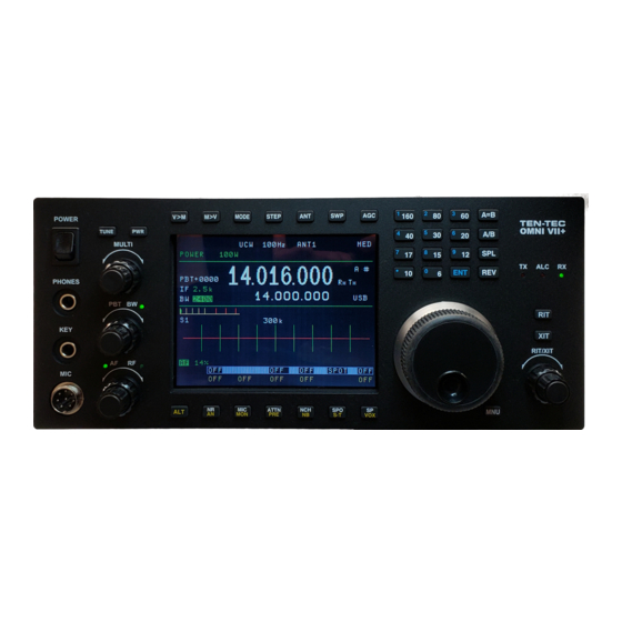
- Page 1 OMNI-VII Model 588 Programmers Reference Guide Revision 1.009 Rev 1.009 OMNI-VII Programmer’s Reference Guide 1 of 63 OMNI-VII Firmware Updates at www.rfsquared.com...
-
Page 2: Table Of Contents
Introduction........................4 Conventions Used in This Manual ................6 Interface Settings ...................... 7 Serial Connection ....................7 Ethernet Connection ....................8 The OMNI-VII Command Set ..................9 OMNI-VII Command Set Quick List ..............10 RADIO MODE Command Set ................15 Frequency Tuning.................... - Page 3 Sidetone Volume ....................38 SPOT Volume ..................... 39 FSK Mark High/Low................... 39 I-F Filter Selection....................40 I-F Filter Enable ....................40 Antenna ....................... 41 Monitor........................ 41 Transmit Power ....................42 SPOT Tone On/Off ..................... 42 PREAmp On/Off ....................43 Remote Tune ....................... 43 Split State –...
-
Page 4: Introduction
PC based OMNI-VII (Model 588) Interface program. The Ten-Tec OMNI-VII DSP HF transceiver is a product that is defined more by firmware than hardware. As such, it is subject to change based on customer needs. It is advisable to check for a more recent update at the Ten-Tec firmware update site, www.rfsquared.com. - Page 5 Since the OMNI-VII provides future growth for up to a total of 6 completely independent modes. It is possible that even further additions will be made to support the added capabilities of the other modes. Holdings down a digit on the band stack keyboard of the front panel accesses each mode.
-
Page 6: Conventions Used In This Manual
Conventions Used in This Manual Information contained in this document applies to firmware version 0.114 and later. Numeric Types: 0x0A Hexadecimal Numbers. <dn> 8 bit numbers Decimal Number. ‘A’ ASCII character code. Example: ASCII ‘A’ is 0x41. <CR> a byte containing the value of <0x0d> for a carriage return Rev 1.009 OMNI-VII Programmer’s Reference Guide 6 of 63... -
Page 7: Interface Settings
Interface Settings Serial Connection The RS-232 serial interface on the OMNI-VII is handled via a 16C550 UART located on the DSP/Logic board. The interface parameters are fixed at 57,600 baud, No Parity, 8 Data bits, 1 Stop bit. The UART uses hardware handshaking to control the data flow between the PC and the radio. -
Page 8: Ethernet Connection
the other device is a DTE, then you will need to use a standard straight RS232 interface cable. In order to use the OMNI-VII in remote mode, but you intend on controlling the rig only by the serial port, then it is suggested that you disable the Ethernet activities of the OMNI-VII. -
Page 9: The Omni-Vii Command Set
The OMNI-VII Command Set The command set is extensive and every effort has been made to keep the individual commands as simple as possible. Although the OMNI-VII Serial interface operates at 57,600 baud and the Ethernet interface operates at 10Mbps short commands are used to keep the processing overhead to a minimum. -
Page 10: Omni-Vii Command Set Quick List
OMNI-VII Command Set Quick List Command Set Format Set Note Radio Remote Query Format Query return val Mode Mode Set/Get *A<d3 d2 d1 d0> <CR> d3..d0 4-byte binary Main Freq ?A <CR> A<d3 d2 d1 d0> <CR> or @Afnnnnnnnn <CR> ASCII *A12345678<CR>... - Page 11 Command Set Format Set Note Radio Remote Query Format Query return val Mode Mode Set/Get DSP *W <d0> <CR> Range = 0..0x24 RX Filter ?W <CR> W<d0><CR> Where At (Query only, without ?) <0x0d><0x0d> XX <CR> “ RADIO START – xxxxxx”...
- Page 12 Command Set Format Set Note Radio Remote Query Format Query return val Mode Mode Transmit ?C1J <CR> 70Hz.300Hz Roll Off C1J <d0> <CR> Set/Get *C1K <d0> <CR> Range = 0.0x7f – 15ms..1s External ?C1K <CR> C1K <d0> <CR> T/R Delay Set/Get *C1L <d0>...
- Page 13 Command Set Format Set Note Radio Remote Query Format Query return val Mode Mode Set/Get *C1Y <d0> <CR> Range = 0.0x01 Off, On SPOT ?C1Y <CR> C1Y <d0> <CR> Set/Get *C1Z <d0> <CR> Range = 0.0x01 Off, On PreAmp ?C1Z <CR> C1Z <d0>...
- Page 14 Command Set Format Set Note Radio Remote Query Format Query return val Mode Mode Speaker ?C2O<CR> UnMute / Mute MUTE C2O <d0> <CR> TRIP Gain *C2P <d0> <CR> Range=”1”,”9” for shiftlvl ?C2P<CR> C2P <d0> <CR> Rev 1.009 OMNI-VII Programmer’s Reference Guide 14 of 63 OMNI-VII Firmware Updates at www.rfsquared.com...
-
Page 15: Radio Mode Command Set
RADIO MODE Command Set In this section, we will explore the command set available on the Serial Interface when the radio is in RADIO MODE. Unless otherwise specified, queries use the same command letter, except that instead of an Asterisk, use a “?”. E.g. *A sets main frequency, ?A requests Main Frequency. -
Page 16: Agc Mode Control
AGC Mode Control The Automatic Gain Control (AGC) Mode selections available in the OMNI-VII are SLOW, MEDIUM, FAST, or OFF. The AGC mode can be changed at any time to take advantage of changing band conditions. AGC can be turned OFF so that the receiver gain is then controlled manually by the RF Gain control. -
Page 17: Rf Gain
RF Gain The relative RF gain can be controlled over a range of 0-127. A setting of 0 represents full RF Gain whereas a setting of 127 (0x7f) represents the minimum RF Gain level. Because this control directly affects the RF Hardware, this will directly affect S- Units responses and Squelch settings. -
Page 18: Noise Blanker, Noise Reduction, And Automatic Notch
Noise Blanker, Noise Reduction, and Automatic Notch The Noise Blanker, Noise Reduction, and Automatic Notch are available for use in all modes. They can be used individually or together. Format: ‘*’ ‘K’ <d2> <d1> <d0> <CR> Where: ‘*’ = the ASCII ‘*’ symbol (0x2a) K = the ASCII ‘K’... -
Page 19: Passband Tuning (Pbt)
Passband Tuning (PBT) The passband tuning range of the OMNI-VII is +/-8192Hz. Setting the PBT to zero will turn the passband tuning control off. The data format is a 2 byte binary number which represents the PBT value in Hz. Format: ‘*’... -
Page 20: Version - Query Only
Version – Query Only The version of the software in the OMNI-VII can be retrieved with this command. Format: ‘?’ ‘V’ <CR> Where: ‘?’ = the ASCII ‘?’ symbol (0x3F) V = the ASCII ‘V’ character (0x56) Returns: “VER “ ABCD “-588 “ [“REMOTEx” or “RADIO x”] <CR> Where: ABCD = ASCII A.BCD version number Where:... -
Page 21: Where - At
Where – AT This command simply performs a notify. Format: XX <CR> Where: X = the ASCII ‘X’ character (0x58) Example: XX<CR> Returns: “ RADIO START – RADIO ” <CR> Returns: “ RADIO START – REMOTE” <CR> Note: The Boot Loader returns: “ DSP START” <CR> Execution Control The OMNI-VII has different execution events that are used in programming the radio or in restoring original defaults. -
Page 22: Sunit - Query Only
SUNIT – Query Only The OMNI-VII can report the signal strength of the receive hardware. This is not affected by the Attenuator setting, nor the Pre-Amp. It returns the S-Units in receive mode, and the forward / reflected power readings in transmit modes. Format: ‘?’... -
Page 23: Transmit
Transmit The OMNI-VII can be put into transmit mode by sending the Transmit Command. This command is available in the both RADIO mode and REMOTE Mode. It can be received via either the serial or Ethernet port. In RADIO mode, it only turns on and off transmits. -
Page 24: Split State - Radio Mode
Frequency Tuning Query (already defined in the Frequency Tuning section of this manual), and the other is the response to the ?RMM Main Mode Query. The ?RMM response format follows the values as identified for the Ten-Tec Orion. Format: ‘?’... -
Page 25: Remote Mode Command Set
REMOTE MODE Command Set In this section, we will explore the command set available on the Serial Interface when the radio is in REMOTE MODE. Note: ALL of the commands that were available in RADIO MODE are also available in REMOTE MODE. Where these commands have differences, they will be shown in this section. -
Page 26: Ethernet Settings - Query Only
Ethernet Settings – Query Only In Remote Mode, the Ethernet settings can be queried. This includes the MAC Address of the radio, the current state of RIPping, and the IP Address of the Computer that the Radio is RIPping with. The RIP items are provided so that they can be checked before trying to RIP, and if the radio is already RIPping, then the new program should not attempt it. -
Page 27: Frequency Tuning
Frequency Tuning Frequency Tuning Selection in REMOTE MODE permits entry of the frequency in the same format as is available in RADIO MODE, and also two more modes of ASCII entry. The 4-byte binary format requires the <CR> to be present at the 6 byte location (assuming the * is at location 1). -
Page 28: Receive / Transmit Offset
Receive / Transmit Offset The OMNI-VII can adjust the current receive and or transmit frequency by a given offset amount from the base receive or transmit frequency. This single offset value has a range of 8192 to –8192Hz. Format: ‘*’ ‘L’ <d2> <d1> <d0> <CR> Where: ‘*’... -
Page 29: Audio Source
Audio Source The audio source for the OMNI-VII can be selected as either the MIC, the back panel LINE input, or a summation of BOTH. Format: ‘*’ ‘C1A’ <d0> <CR> Where: ‘*’ = the ASCII ‘*’ symbol (0x2a) C1A = the ASCII ‘C1A’ characters (<0x43><0x31><0x41>) <d0>... -
Page 30: Keying Loop On/Off
Keying Loop On/Off The keying loop on the back panel of the OMNI-VII can be turned on or ignored. Format: ‘*’ ‘C1B’ <d0> <CR> Where: ‘*’ = the ASCII ‘*’ symbol (0x2a) C1B = the ASCII ‘C1B’ characters (<0x43><0x31><0x42>) <d0> = binary 0 for Keying Loop Off (ignore it, key anyway). = binary 1 for Keying Loop On (wait for tx enable). -
Page 31: Mic Gain
Mic Gain The relative Mic Gain can be controlled over a range of 0-127. A setting of 0 represents Mic Gain Off, whereas a setting of 127 (0x7f) represents the maximum Mic Gain setting of 100%. Format: ‘*’ ‘C1D’ <d0> <CR> Where: ‘*’... -
Page 32: Speech Processor
Speech Processor The relative amount of Speech Processing can be controlled over a range of 0-127. A setting of 0 represents the least amount of Speech processing, whereas a setting of 127 (0x7f) represents the maximum Speech Processing setting of 100%. Format: ‘*’... -
Page 33: Rx Equalizer
RX Equalizer The RX Equalizer is selectable in 1-dB steps from high pitched at –20 to essentially flat response at 0dB to very bassy at +20dB. These 41 steps are controlled over a range of 0-127. A setting of 0 represents the –20dB selection, a setting of 63 (0x3f) represents the flat response of 0dB, and a setting of 127 represents the +20dB selection. -
Page 34: Transmit Roll Off
Transmit Roll Off The Transmit Roll Off can be set to 70-300Hz. This determine shwere the low end frequency responses of an SSB transmit signal begins to attenuate. Format: ‘*’ ‘C1J’ <d0> <CR> Where: ‘*’ = the ASCII ‘*’ symbol (0x2a) C1J = the ASCII ‘C1J’... -
Page 35: Sidetone Frequency
Sidetone Frequency The Sidetone Frequency can be set to 0-1270Hz in 10 Hz steps. Format: ‘*’ ‘C1L’ <d0> <CR> Where: ‘*’ = the ASCII ‘*’ symbol (0x2a) C1L = the ASCII ‘C1L’ characters (<0x43><0x31><0x4C>) <d0> = 7 bit Sidetone Frequency Selection (0x00 to 0x7f) Example1: *C1L<0x64><CR>... -
Page 36: Transmit Enable
Transmit Enable This controls whether attempts to transmit will produce RF or not. It is possible to practice CW, listen to the sidetone, and not transmit. The range is from 0 for transmitter disabled, to 1 for transmitter enabled. Format: ‘*’... -
Page 37: Sideband Transmit Bandwidth
Sideband Transmit Bandwidth The Sideband Transmit Bandwidth can be set to 1000 – 4000Hz. Format: ‘*’ ‘C1O’ <d0> <CR> Where: ‘*’ = the ASCII ‘*’ symbol (0x2a) C1O = the ASCII ‘C1O’ characters (<0x43><0x31><0x4F>) <d0> = 7 bit transmit bandwidth select (0x00 to 0x10) Example: *C1O<0x05><CR>... -
Page 38: Auto Tuner
Auto Tuner This controls whether the OMNI-VII will control the optional Auto Tuner or not. It is possible to have an Auto Tuner installed, yet you may want to force it to not use the Auto Tuner under certain conditions. The range is from 0 for Auto Tuner Not Installed, to 1 for Auto Tuner Installed. -
Page 39: Spot Volume
SPOT Volume The relative SPOT Volume can be controlled over a range of 0-127. A setting of 0 represents SPOT Off, whereas a setting of 127 (0x7f) represents the maximum SPOT Volume setting of 100%. Format: ‘*’ ‘C1R’ <d0> <CR> Where: ‘*’... -
Page 40: I-F Filter Selection
I-F Filter Selection The I-F Filter can be selected from 20kHz to 300Hz or even Automatic Selection based on the Receive Bandwidth selection. Format: ‘*’ ‘C1T’ <d0> <CR> Where: ‘*’ = the ASCII ‘*’ symbol (0x2a) C1T = the ASCII ‘C1T’ characters (<0x43><0x31><0x54>) <d0>... -
Page 41: Antenna
Antenna The OMNI-VII has connections for two HF Transceiver Antennas, and one HF Receiver Antenna. These are referred to as ANT1, ANT2, and RXAUX on the radio selection menus. Format: ‘*’ ‘C1V <d0> <CR> Where: ‘*’ = the ASCII ‘*’ symbol (0x2a) C1V= the ASCII ‘C1V characters (<0x43><0x31><0x56>) <d0>... -
Page 42: Transmit Power
Transmit Power The relative Transmit Power can be controlled over a range of 0-127. A setting of 0 represents lowest power setting, and 127 (0x7f) represents maximum transmit power level. The OMNI-VII allows you to select 0…127, which represents 0..100 Watts. However, the lower value will be limited to no lower than 5Watts. -
Page 43: Preamp On/Off
PREAmp On/Off This controls whether the OMNI-VII will engage the Pre-Amplifier or not. The range is from 0 for Pre-Amplifier OFF, to 1 for Pre-Amplifier ON. Format: ‘*’ ‘C1Z’ <d0> <CR> Where: ‘*’ = the ASCII ‘*’ symbol (0x2a) C1Z = the ASCII ‘C1Z’ characters (<0x43><0x31><0x5A>) <d0>... -
Page 44: Split State - Extended Format
Split State – Extended Format Split State Selection in REMOTE MODE is available in the same command format as in RADIO MODE using the *N ?N command query. Split State is also adjustable in the extended command set as follows: (This extended command gives no additional functionality over the N command. -
Page 45: Anti Vox Level
ANTI VOX Level The relative ANTI VOX Level can be controlled over a range of 0-127. A setting of 0 represents lowest Anti-VOX setting, and 127 (0x7f) represents maximum Anti-VOX. Format: ‘*’ ‘C2D’ <d0> <CR> Where: ‘*’ = the ASCII ‘*’ symbol (0x2a) C2D = the ASCII ‘C2D’... -
Page 46: Cw Keyer Mode
CW Keyer Mode This controls whether the OMNI-VII internal keyer mode operates in Mode A or Mode B mode, or OFF Format: ‘*’ ‘C2F’ <d0> <CR> Where: ‘*’ = the ASCII ‘*’ symbol (0x2a) C2F = the ASCII ‘C2F’ characters (<0x43><0x32><0x56>) <d0>... -
Page 47: Manual Notch On/Off
Manual NOTCH On/Off This controls whether the OMNI-VII Manual Notch is engaged or not. Format: ‘*’ ‘C2H’ <d0> <CR> Where: ‘*’ = the ASCII ‘*’ symbol (0x2a) C2H = the ASCII ‘C2H’ characters (<0x43><0x32><0x48>) <d0> = binary 0 = Manual Notch OFF = binary 1 = Manual Notch ON Example: *C2H<0x01><CR>... -
Page 48: Manual Notch Width
Manual NOTCH Width The relative Manual NOTCH Width can be controlled over a range of 0-127. A setting of 0 represents lowest Manual NOTCH Width of 10 Hz, and 127 (0x7f) represents maximum Manual NOTCH Width of 300Hz The formula is ((315 – 10) / (127 – 1)) * MANNCHWIDTH_Selected Hz Format: ‘*’... -
Page 49: Vox On/Off
VOX On/Off VOX can be turned on and off. Format: ‘*’ ‘C2M’ <d0> <CR> Where: ‘*’ = the ASCII ‘*’ symbol (0x2a) C2M = the ASCII ‘C2M’ characters (<0x43><0x32><0x4D>) <d0> = binary 0 = VOX OFF = binary 1 = VOX ON Example1: *C2M<0x00><CR>... -
Page 50: Radio Speaker On/Off
RADIO SPEAKER ON/OFF The Speaker on the Radio can be muted remotely. This also affects the external speaker connected to the SPKR jack on the back of the radio. Format: ‘*’ ‘C2O’ <d0> <CR> Where: ‘*’ = the ASCII ‘*’ symbol (0x2a) C2O = the ASCII ‘C2O’... -
Page 51: Operation With Optional 302 Remote Encoder
Operation with Optional 302 Remote Encoder The optional 302 Remote Control provides the OMNI-VII with a remote tuning encoder direct frequency keypad and auxiliary function keys. The 302 connects to the REMOTE jack on the back of the OMNI-VII. The additional features provided by the 302 are actually contained within the OMNI-VII. -
Page 52: Pod Passthru Notification
POD PASSTHRU Notification The format of the POD PASSTHRU Notification from the OMNI-VII to the computer via the serial port that a POD key has been pressed/released is as follows: Format: ‘Q’ <d0> <CR> Where: Q = the ASCII ‘Q’ character (0x51) <d0>... -
Page 53: Pod Encoder Notification
POD ENCODER Notification The format of the POD ENCODER Notification from the OMNI-VII to the computer via the serial port that the POD Encoder has been turned is as follows: Format: ‘!’ <d0> <CR> Where: ! = the ASCII ‘!’ character (0x21) <d0>... -
Page 54: Serial Device Control Via Ethernet
Serial Device Control via Ethernet The OMNI-VII provides a way to control devices that are connected to the OMNI- VII’s serial interface, by using the “Serial Pass Thru” command protocol on the Ethernet interface. It also allows the OMNI-VII to echo back out on the Ethernet Interface, data bytes it receives in on the serial interface port, “Serial Echo Mode”. -
Page 55: Serial Echo Mode
Serial Echo Mode Serial Echo Mode will enable the OMNI-VII to take bytes received on the serial interface port and echo them to the Ethernet interface port. To get into this mode, the Host PC can send a SERIAL_ECHO command to the OMNI-VII. - Page 56 From OMNI-VII to PC via Ethernet Interface From Barney to OMNI-VII Serial Interface Port From OMNI-VII to PC via Ethernet Interface From Barney to OMNI-VII Serial Interface Port From OMNI-VII to PC via Ethernet Interface Rev 1.009 OMNI-VII Programmer’s Reference Guide 56 of 63 OMNI-VII Firmware Updates at www.rfsquared.com...
-
Page 57: Cwtype
CWType The OMNI-VII provides a way to help out with CW transmits in REMOTE mode. The OMNI-VII provides an interface command to send a CW Character. In order for this to work, the OMNI-VII’s Internal Keyer needs to be turned on, either in Mode A or Mode B, and when this command is received, the CW Character will be clocked out given the selected CW speed, Rise/Fall, etc. - Page 58 Note2: The OMNI-VII handles ascii for upper and lower case characters, and converts them to the standard dit/dah pattern for that character (e.g. A and a both equal dit dah) So it is not necessary to convert key codes into either upper or lower case making keyboard entry possible.
-
Page 59: Ethernet Audio
Ethernet Audio The OMNI-VII in REMOTE MODE provides audio over the Ethernet. This is not available over the serial interface. This data is packed in a UDP packet. RIP (Radio over IP) Introduction RIP is the audio that goes from the OMNI-VII to the computer. This is the actual over the air received audio that the OMNI-VII is tuned to receive. -
Page 60: Rip Audio Packet Format
RIP Audio Packet Format We do not cover Internet Protocols, please refer to other documents for that. We will cover the data as it pertains to the RIP Audio. The RIP audio is encapsulated in a UDP packet with the source and destination port numbers set to the UDP Command Port+2. The UDP Packet contains an RTP (Real Time Protocol) format packet that contains the audio. -
Page 61: Trip Audio Packet Format
TRIP Audio Packet Format The TRIP audio is encapsulated in a UDP packet with the source and destination port numbers set to the UDP Command Port+4. The UDP Packet only contains a 16 bit counter and the actual audio to transmit data. The format of the data packet used for the OMNI-VII are as follows for non-compressed TRIP: Octet 0 Packet Counter... -
Page 62: Document Revision History
Document Revision History Date: Revision: Modifications March 7, 2007 1.001 • Modified the Transmit Power to indicate that it not only returns selected power, but also forward and reflected power. • Added “ – REMOTE” or “ – RADIO “ text to the Where At query. - Page 63 October 16, 2007 1.006 • Added example showing that the OMNI-VII will limit the requested frequency if it is out of the supported range. • Added notation of change of meaning of CW Weighting from version 1.022 onwards is now 0.0x7f = 0 to 50%.
Need help?
Do you have a question about the OMNI-VII 588 and is the answer not in the manual?
Questions and answers