
Related Manuals for Technosoft IDM240-5EI

Summary of Contents for Technosoft IDM240-5EI
- Page 1 IDM240-5EI IDM640-8EI Intelligent Servo Drive Intelligent Drives Technical Reference © Technosoft 2011...
- Page 3 TECHNOSOFT IDM240-5EI IDM640-8EI Technical Reference P091.048.051.IDM.UM.0711 Technosoft S.A. Avenue des Alpes 20 CH-2000 NEUCHATEL Switzerland Tel.: +41 (0) 32 732 5500 Fax: +41 (0) 32 732 5504 contact@technosoftmotion.com www.technosoftmotion.com...
-
Page 5: Read This First
Whilst Technosoft believes that the information and guidance given in this manual is correct, all parties must rely upon their own skill and judgment when making use of it. Technosoft does not assume any liability to anyone for any loss or damage caused by any error or omission in the work, whether such error or omission is the result of negligence or any other cause. - Page 6 Help of the EasySetUp software – describes how to use EasySetUp to quickly setup any Technosoft drive for your application using only 2 dialogues. The output of EasySetUp is a set of setup data that can be downloaded into the drive EEPROM or saved on a PC file.
- Page 7 TML_LIB_LabVIEW v2.0 (part no. P091.040.LABVIEW.v20.UM.xxxx) – explains how to program in LabVIEW a motion application for the Technosoft intelligent drives using TML_LIB_Labview v2.0 motion control library for PCs. The TML_Lib_LabVIEW includes over 40 ready-to-run examples. TML_LIB_S7 (part no. P091.040.S7.UM.xxxx) – explains how to program in a PLC Siemens series S7-300 or S7-400 a motion application for the Technosoft intelligent drives using TML_LIB_S7 motion control library.
-
Page 8: Table Of Contents
CAN Communication – J10 Connector ............50 3.2.8. Connectors Type and Mating Connectors............ 53 3.3. DIP-Switch Settings................53 3.4. LED Indicators..................56 3.5. First Power-Up ..................56 Step 2. Drive Setup................... 57 4.1. Installing EasySetUp ................57 © Technosoft 2011 IDMx40 Technical Reference... - Page 9 DSP-402 and Manufacturer Specific Device Profile Overview..... 65 5.1.4. Checking Setup Data Consistency .............. 66 5.2. Using the built-in Motion Controller and TML ........66 5.2.1. Technosoft Motion Language Overview ............66 5.2.2. Installing EasyMotion Studio................ 67 5.2.3. Getting Started with EasyMotion Studio ............67 5.2.4.
- Page 10 DC brushed motor with quadrature encoder on load and tacho on motor 88 6.12.3. Stepper motor open-loop control. No feedback device......89 6.12.4. Stepper motor open-loop control. Incremental encoder on load....89 6.12.5. Stepper motor closed-loop control. Incremental encoder on motor..89 © Technosoft 2011 IDMx40 Technical Reference...
- Page 11 DC brushed motor with tacho on motor ............ 90 6.13.4. Stepper motor open-loop control. No feedback device or incremental encoder on load ......................90 6.13.5. Stepper motor closed-loop control. Incremental encoder on motor..91 Memory Map ..................... 92 © Technosoft 2011 IDMx40 Technical Reference...
-
Page 12: Safety Information
ELECTRICAL SHOCKS. DO NOT TOUCH LIVE PARTS WHILE THE POWER SUPPLIES ARE ON TO AVOID ELECTRIC ARCING AND HAZARDS, NEVER WARNING! CONNECT / DISCONNECT WIRES FROM THE DRIVE WHILE THE POWER SUPPLIES ARE ON © Technosoft 2011 IDMx40 Technical Reference... -
Page 13: Cautions
THE POWER SUPPLIES CONNECTED TO THE DRIVE CAUTION! MUST COMPLY WITH THE PARAMETERS SPECIFIED IN THIS DOCUMENT TROUBLESHOOTING AND SERVICING ARE PERMITTED CAUTION! ONLY FOR PERSONNEL AUTHORISED BY TECHNOSOFT THE DRIVE CONTAINS ELECTROSTATICALLY SENSITIVE COMPONENTS WHICH DAMAGED CAUTION! INCORRECT HANDLING. THEREFORE THE DRIVE SHALL... -
Page 14: Product Overview
PLC functionality in a single compact unit and are capable to execute complex motions without requiring intervention of an external motion controller. Using the high- level Technosoft Motion Language (TML) the following operations can be executed directly at drive level:... -
Page 15: Key Features
CANopen – compatible with CiA standards: DS301 and DSP402 TMLCAN – compatible with all Technosoft drives with CANbus interface • Motor temperature sensor interface • 4K×16 SRAM for data acquisitions and 8K×16 E ROM for setup data and TML programs... -
Page 16: Supported Motor-Sensor Configurations
(rotary or linear). Therefore, the Nominal values cover all cases. Higher values are possible in specific configurations. For details contact Technosoft 1-2kHz cover all cases. Higher values equal with torque loop update frequency are possible with quadrature encoders... - Page 17 SI units (or derivatives) refer to the load, while the same commands, expressed in IU units, refer to the motor. Motion commands can be referred to the motor by setting in EasySetUp a rotary to rotary transmission with ratio 1:1 Available only for the IDMx40 CAN executions © Technosoft 2011 IDMx40 Technical Reference...
- Page 18 Therefore, the motion commands (for speed and acceleration) expressed in SI units (or derivatives) refer to the load , while the same commands, expressed in IU units, refer to the motor IDMx40 Figure 2.6. DC brushed rotary motor. Speed/torque control. Tachometer on motor © Technosoft 2011 IDMx40 Technical Reference...
- Page 19 The motion commands in both SI and IU units refer to the load. IDMx40 Figure 2.9. Encoder on load. Closed-loop control: load position, open-loop control: motor speed 3-phase step motor configuration is available only for the IDMx40 CAN versions © Technosoft 2011 IDMx40 Technical Reference...
-
Page 20: Idmx40 Dimensions
Figure 2.10. Encoder on motor shaft. Closed-loop control: motor position, speed or torque 2.4. IDMx40 Dimensions The next figure presents the IDMx40 drives dimensions. 26 mm 136 mm (5.354”) (1.024”) 4 mm (0.157”) Figure 2.11. IDMx40 drives dimensions © Technosoft 2011 IDMx40 Technical Reference... -
Page 21: Electrical Specifications
= 0…40°C, V = 24 V = 24 V , CAN_V+ = 24 V 24 VPLC = 48 V (IDM240-5EI) or 80 V (IDM640-8EI); Supplies start-up / shutdown sequence: -any- ; Load current 5 A (IDM240-5EI) or 8 A (IDM640-8EI) Operating Conditions Min. - Page 22 Nominal values, including ripple Absolute maximum values, continuous Supply voltage Absolute maximum values, surge -100 † (duration ≤ 10ms) = 12V Supply current = 24 V = 48 V ESD Protection Human Body Model ±25 ±30 © Technosoft 2011 IDMx40 Technical Reference...
- Page 23 Measured between +V and GND. Min. Typ. Max. Units Nominal values, including ripple & braking- induced over-voltage up to ±25% Absolute maximum values, continuous Supply voltage IDM240-5EI Absolute maximum values, surge -0.5 † (duration ≤ 10ms) Nominal values, including ripple & braking- induced over-voltage up to ±25%...
- Page 24 CAN-Bus operating at 1Mbit/s Isolation voltage rating Between CAN_GND and drive GND Motor Outputs All voltages referenced to GND. Min. Typ. Max. Units Motor output current IDM240-5EI Continuous operation Motor output current IDM640-8EI Continuous operation Motor output current, peak -16.5 +16.5 ±20 ±22 ±24...
- Page 25 Input hysteresis Differential mode Referenced to GND Input common mode range † Absolute maximum, surge (duration ≤ 1s) Single-ended mode kΩ Input impedance Ω Differential mode (see Input Frequency ±2 ESD Protection Human Body Model © Technosoft 2011 IDMx40 Technical Reference...
- Page 26 Standards compliance TIA/EIA-485-C Recommended transmission line Ω Measured at 1MHz impedance 11520 Bit rate Depending on software settings 9600 Baud Number of network nodes Depending on software settings ±15 ESD Protection Human Body Model © Technosoft 2011 IDMx40 Technical Reference...
- Page 27 “FS” stands for “Full Scale” † Stresses beyond those listed under “absolute maximum ratings” may cause permanent damage to the device. Exposure to absolute maximum-rated conditions for extended periods may affect device reliability. © Technosoft 2011 IDMx40 Technical Reference...
- Page 28 PWM frequency with the motor parameters in order to avoid possible motor damage. – the nominal current Stand-alone operation, vertical mounting Fixed on metallic surface, vertical mounting. Temperature is measured at the contact area between the IDMx40 and the heat sink. © Technosoft 2011 IDMx40 Technical Reference...
- Page 29 Figure 2.17. Power De-rating with PWM frequency frequency Figure 2.18. Over-current diagram for IDM240 Figure 2.19. Over-current diagram for IDM640 – the output voltage, V – the motor supply voltage – the nominal power © Technosoft 2011 IDMx40 Technical Reference...
-
Page 30: Step 1. Hardware Installation
The IDMx40 drive was designed to be cooled by natural convection. It can be mounted horizontally (with label upwards) inside a cabinet (see Figure 3.1), with motor wires going down. Figure 3.1. Recommended mounting of IDMx40 in a cabinet © Technosoft 2011 IDMx40 Technical Reference... - Page 31 D (see Figure 3.1) should permit to connect the cables to the drive (at least the screw driver height). Required wiring distance > 120mm (4.72 in) > 100mm (3.93 in) > 25mm (2.36 in) © Technosoft 2011 IDMx40 Technical Reference...
-
Page 32: Connectors And Connection Diagrams
3.2. Connectors and Connection Diagrams 3.2.1. Connectors Layout Figure 3.2. IDM240-5EI and IDM640-8EI connectors layout © Technosoft 2011 IDMx40 Technical Reference... -
Page 33: Identification Labels
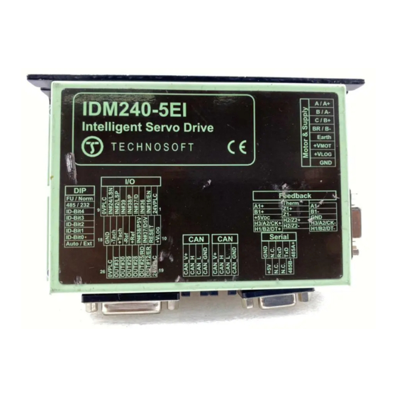
3.2.2. Identification Labels Figure 3.3. IDM240-5EI Identification Label Figure 3.4. IDM640-8EI (CAN execution) Identification Label Figure 3.5. IDM640-8EI (CANopen execution for Brushless and DC motors with incremental encoder ) Identification Label Figure 3.6. IDM640-8EI (CANopen execution for Step motors with incremental encoder ) Identification Label ©... -
Page 34: Motor & Supply - J2 Connector
• Earth Earth connection Positive terminal of the motor supply: 12 to 80 V Positive terminal of the logic supply: 12 to 48 V Negative terminal of the +V and +V external power supplies © Technosoft 2011 IDMx40 Technical Reference... - Page 35 It is completely insulated from all electric signals of IDMx40. This feature may facilitate avoiding ground loops. It is recommended that Earth be connected to GND at only one point, preferably close to the V supply output. © Technosoft 2011 IDMx40 Technical Reference...
- Page 36 IDMx40 Figure 3.8. J2 – Brushless motor connection © Technosoft 2011 IDMx40 Technical Reference...
- Page 37 IDMx40 Figure 3.9. J2 – DC brushed motor connection © Technosoft 2011 IDMx40 Technical Reference...
- Page 38 It is completely insulated from all electric signals of IDMx40-8EI this feature may facilitate avoiding ground loops. It is recommended that Earth be connected to GND at only one point, preferably close to the V supply output. © Technosoft 2011 IDMx40 Technical Reference...
- Page 39 Figure 3.12. J2 – Connection of a 2- phase motor with 2 coils per phase in phase motor with 2 coils per phase in parallel series Figure 3.13. J2 – Connection of a 3-phase motor Available only for IDMx40 CAN executions © Technosoft 2011 IDMx40 Technical Reference...
- Page 40 470µF between the switch and the drive, to reduce the slew-rate rising slope of the motor supply voltage. IDMx40 Figure 3.15. J2 – Motor supply connection – Alternative in-rush current limitation © Technosoft 2011 IDMx40 Technical Reference...
- Page 41 = 63V (IDM240) / 92V (IDM640) is the over-voltage protection limit = 100μF (IDM240) / 200μF (IDM640) is the drive internal capacitance Drive = 48V (IDM240) / 80V (IDM640) is nominal motor supply voltage © Technosoft 2011 IDMx40 Technical Reference...
- Page 42 The brake resistor value must be chosen to respect the following conditions: 1. to limit the maximum current below the drive peak current I = 16.5A PEAK > PEAK 2. to sustain the required braking power: © Technosoft 2011 IDMx40 Technical Reference...
- Page 43 (see Remark 1) × × CYCLE or t – the time interval between braking cycles must be increased CYCLE THE BRAKE RESISTOR MAY HAVE HOT SURFACES WARNING! DURING OPERATION. © Technosoft 2011 IDMx40 Technical Reference...
-
Page 44: Feedback - J13A Connector
*) In application configurations without any encoder feedback, this input may be used as a general-purpose input. *) In application configurations without any Hall or second encoder feedback, this input may be used as a general-purpose input. © Technosoft 2011 IDMx40 Technical Reference... - Page 45 HANDLED ONLY IN AN ESD PROTECTED ENVIRONMENT J13A - Feedback Connector IDM240-5EI IDMx40 - Single-ended / open-collector encoders - IDM640-8EI J13A 3 x 4K7 SHIELD Connected +3.3V to case Figure 3.16. J13A – Single-ended / open-collector encoder connection © Technosoft 2011 IDMx40 Technical Reference...
- Page 46 Figure 3.17. J13A – Differential (RS-422) encoder connection Remark: For noisy electromagnetic environments or long encoder lines add 120Ω termination resistors between the positive and negative line, close to the drive. (For details see RS-422 standard). © Technosoft 2011 IDMx40 Technical Reference...
- Page 47 Figure 3.18. J13A – Second encoder - differential (RS-422) connection Remarks: 1.For long encoder lines add 120Ω termination resistors close to the drive. (For details see RS-422 standard). 2. Connect the +5V just to one IDMx40 drive, on the master or slave. © Technosoft 2011 IDMx40 Technical Reference...
- Page 48 - Second Encoder - single (RS-422) - J13A 3 x 4K7 H1/B2/DT+ H2/Z2+ H3/A2/CK+ +3.3V 3 x 3K1 +1.6V SHIELD Connected to case encoder Master Master inputs Figure 3.19. J13A – Second encoder – single ended (RS-422) connection © Technosoft 2011 IDMx40 Technical Reference...
- Page 49 Motor phases IDM240-5EI IDMx40 IDM640-8EI Master Master J13A Encoder Motor phases IDM240-5EI IDMx40 IDM640-8EI J13A Slave Second Slave Encoder Encoder Figure 3.20. J13A – Master - Slave connection using second encoder input © Technosoft 2011 IDMx40 Technical Reference...
- Page 50 J13A - Feedback Connector IDM240-5EI IDMx40 - Single-ended / open-collector Hall - IDM640-8EI J13A 3 x 4K7 H1/B2/DT+ H2/Z2+ H3/A2/CK+ SHIELD Connected +3.3V to case Figure 3.21. J13A – Single-ended / open-collector Hall connection © Technosoft 2011 IDMx40 Technical Reference...
- Page 51 3 x 3K1 +1.6V SHIELD Connected to case Figure 3.22. J13A – Differential (RS-422) Hall connection Remark: For long Hall lines add 120Ω termination resistors close to the drive. (For details see RS-422 standard). © Technosoft 2011 IDMx40 Technical Reference...
- Page 52 If the IDMx40 5V supply output is used by another device (like for example an encoder) and the connection cable is longer than 5 meters, add a decoupling capacitor near the supplied device, between the +5V and GND lines. The capacitor value can be 1...10 μF, rated at 6.3V. © Technosoft 2011 IDMx40 Technical Reference...
-
Page 53: Analog & Digital I/O - J9 Connector
Can be used as PULSE input in Pulse & Direction motion mode +Ref +/-10 V differential analog input. May be used as analog position, speed or torque reference -Ref +Tach +/-10 V differential analog input. May be used as analog © Technosoft 2011 IDMx40 Technical Reference... - Page 54 24VPLC supply connection is not necessary. 6. The inputs IN#37/D and IN#38/P accept both TTL (5V) and 24V signals and are opto- isolated. These inputs are referenced to the drive logic ground GND © Technosoft 2011 IDMx40 Technical Reference...
- Page 55 IDMx40 Figure 3.24 J9 – Analogue & Digital I/O connections © Technosoft 2011 IDMx40 Technical Reference...
- Page 56 IDMx40 I/O connector. Choose the divider resistances as low as possible, close to the signal source output current limit, to minimize the noise IDMx40 Figure 3.25 J9 – 24 V Pulse & Direction connection © Technosoft 2011 IDMx40 Technical Reference...
- Page 57 (or feedback) is incremented / decremented. 3. When IN#37/D5V is used as DIRECTION input in Pulse & Direction motion mode, the reference (or feedback) is incremented if this pin is pulled low. © Technosoft 2011 IDMx40 Technical Reference...
-
Page 58: Serial Communication - J4 Connector
(internally generated) IDMx40 J4 - RS-232 / RS-485 Connector IDMx40-xxI - RS-232 Connection - 232Tx RS-232 485Tx Transceiver 232Rx 485Rx SHIELD +3.3V RS-485 Transceiver 485 / 232 Figure 3.27. J4 – Serial RS-232 connection © Technosoft 2011 IDMx40 Technical Reference... - Page 59 1. The RS485 serial communication is available only on the CAN executions 2. Use a 9-wire standard 1-to-1 (non-inverting) shielded cable, preferable with metallic or metallized shells (casings) 3. On IDMx40 drive the electrical ground (GND) and the earth/shield are isolated © Technosoft 2011 IDMx40 Technical Reference...
- Page 60 Axis ID for IDMs in the network. For example, if the Host Address is set to 255, then none of the IDMs in the network can have Axis ID set to 255. 2.The PC can be placed in any position in the network. © Technosoft 2011 IDMx40 Technical Reference...
-
Page 61: Can Communication - J10 Connector
All 4 CAN signals are fully insulated from all other IDMx40 circuits (system ground – GND, IO ground – 0VPLC and Earth). Therefore, the CAN network requires a separate supply © Technosoft 2011 IDMx40 Technical Reference... - Page 62 Connect the cable shield to earth/shield. d) Whenever possible, use daisy-chain links between the CAN nodes. Avoid using stubs. A stub is a "T" connection, where a derivation is taken from the main bus. When stubs can’t be © Technosoft 2011 IDMx40 Technical Reference...
- Page 63 AXISID = 2 IDMx40 AXISID = 3 IDMx40 AXISID = 127/255 Figure 3.31. Multiple-Axis CAN network The maximum value of the AXISID is 127 for the IDM640 CANopen execution and 255 for IDMx40 CAN executions © Technosoft 2011 IDMx40 Technical Reference...
-
Page 64: Dip-Switch Settings
OFF: Sets the drive in External (slave) mode. After power-on, the drive waits for commands from an external device. With CANopen protocol, the drive is always in external mode independently of the switch position Remark: All switches are sampled at power-up, and the drive is configured accordingly © Technosoft 2011 IDMx40 Technical Reference... - Page 65 ID – Bit1 ID – Bit0 Technosoft drives can be set with axis ID values from 1 to 255. In CANopen protocol the maximum axis number is 127. When CANopen protocol is used, the CAN communication sees the drives axis ID modulo 128. The correspondence is given in Table 3.2. In order to avoid having multiple devices with the same Axis ID, do not use in the same CANopen ©...
- Page 66 ID areas not covered by CANopen. TechnoCAN protocol offers the possibility to inspect the status of ALL Technosoft drives connected on a CANopen network. This operation is done using EasySetUp or EasyMotion Studio and a single RS-232 link with any of the drives from the CANopen network.
-
Page 67: Led Indicators
Power supply connections and their voltage levels Motor connections Serial cable connections DIP switch positions: all shall be OFF (not pressed) EasySetUp is installed on the PC which is serially connected with the drive (see chapter Step 2. Drive Setup © Technosoft 2011 IDMx40 Technical Reference... -
Page 68: Step 2. Drive Setup
4. Step 2. Drive Setup 4.1. Installing EasySetUp EasySetUp is a PC software platform for the setup of the Technosoft drives. It can be downloaded free of charge from Technosoft web page. EasySetUp comes with an Update via Internet tool through which you can check if your software version is up-to-date, and when necessary download and install the latest updates. -
Page 69: Establish Communication
• Implement on your master the TML commands you need to send to the drives/motors using one of the supported communication channels. The implementation must be done according with Technosoft communication protocols. • Combine TML programming at drive level with one of the other options (see Section 5.3) 4.2.1. -
Page 70: Setup Drive/Motor
If the drive has a different axis ID and you don’t know it, select in the Communication | Setup dialogue at “Axis ID of drive/motor connected to PC” the option Autodetected. 4.2.2. Setup drive/motor Press New button and select your drive type. © Technosoft 2011 IDMx40 Technical Reference... - Page 71 (for example: Incremental encoder). The selection opens 2 setup dialogues: for Motor Setup and for Drive setup through which you can configure and parameterize a Technosoft drive, plus several predefined control panels customized for the product selected.
-
Page 72: Download Setup Data To Drive/Motor
PC via an RS-232 link. If this drive is part of a CANbus network and the PC is serially connected with another drive, use the menu command Communication | Scan Network © Technosoft 2011 IDMx40 Technical Reference... -
Page 73: Setting Canbus Rate
(F/W default) value If there is no CAN rate value set by a valid setup table, with the firmware default value i.e. 500kHz © Technosoft 2011 IDMx40 Technical Reference... -
Page 74: Creating An Image File With The Setup Data
The .sw file can be programmed into a drive: from a CANopen master, using the communication objects for writing data into the drive EEPROM from a host PC or PLC, using the TML_LIB functions for writing data into the drive EEPROM © Technosoft 2011 IDMx40 Technical Reference... -
Page 75: Step 3. Motion Programming
EEPROM Programmer tool, which comes with EasySetUp but may also be installed separately. The EEPROM Programmer was specifically designed for repetitive fast and easy programming of .sw files into the Technosoft drives during production. 5. Step 3. Motion Programming 5.1. -
Page 76: Technocan Extension (For Idmx40 Can Executions)
5.1.2. TechnoCAN Extension (for IDMx40 CAN executions) In order to take full advantage of the powerful Technosoft Motion Language (TML) built into the IDMx40, Technosoft has developed an extension to CANopen, called TechnoCAN through which TML commands can be exchanged with the drives. -
Page 77: Using The Built-In Motion Controller And Tml
EEPROM using the communication objects for writing data into the drive EEPROM. 5.2. Using the built-in Motion Controller and TML One of the key advantages of the Technosoft drives is their capability to execute complex motions without requiring an external motion controller. This is possible because Technosoft drives offer in a single compact package both a state of art digital drive and a powerful motion controller. -
Page 78: Installing Easymotion Studio
EasyMotion Studio is an integrated development environment for the setup and motion programming of Technosoft intelligent drives. It comes with an Update via Internet tool through which you can check if your software version is up-to-date, and when necessary download and install the latest updates. - Page 79 The motion component contains the motion sequences to do. These are described via a TML (Technosoft Motion Language) program, which is executed by the drives/motors built-in motion controller. 5.2.3.1 Create a new project EasyMotion Studio starts with an empty window from where you can create a new project or open a previously created one.
- Page 80 Click on your selection. EasyMotion Studio opens the Project window where on the left side you can see the structure of a project. At beginning both the new project and its first application are named “Untitled”. The application has 2 components: S Setup and M Motion (program). © Technosoft 2011 IDMx40 Technical Reference...
- Page 81 ID=255 (default communication settings). If your drive is powered with all the DIP switches OFF and it is connected to your PC port COM1 via an RS-232 cable, the communication shall establish automatically. © Technosoft 2011 IDMx40 Technical Reference...
- Page 82 Drive Setup (same like on EasySetUp) through which you can configure and parameterize a Technosoft drive. In the Motor setup dialogue you can introduce the data of your motor and the associated sensors. Data introduction is accompanied by a series of tests having as goal to check the connections to the drive and/or to determine or validate a part of the motor and sensors parameters.
- Page 83 TML instructions. Therefore with Motion Wizard you can develop motion programs using almost all the TML instructions without needing to learn them. A TML program includes a main section, followed by the © Technosoft 2011 IDMx40 Technical Reference...
-
Page 84: Creating An Image File With The Setup Data And The Tml Program
For details regarding the .sw file format and how it can be programmed into a drive, see paragraph 4.5 The customization of the interrupt service routines and homing routines is available only for IDMx40 CAN executions Optional for IDM640 CANopen execution © Technosoft 2011 IDMx40 Technical Reference... -
Page 85: Combining Canopen /Or Other Host With Tml
EasySetUp. 5.3.1. Using TML Functions to Split Motion between Master and Drives With Technosoft intelligent drives you can really distribute the intelligence between a CANopen master and the drives in complex multi-axis applications. Instead of trying to command each step of an axis movement, you can program the drives using TML to execute complex tasks and inform the master when these are done. -
Page 86: Customizing The Homing Procedures (For Idmx40 Can Executions)
The procedure for modifying the TML interrupts is similar with that for the homing modes. © Technosoft 2011 IDMx40 Technical Reference... -
Page 87: Using Motion Libraries For Pc-Based Systems
A TML Library for PC is a collection of high-level functions allowing you to control from a PC a network of Technosoft intelligent drives. It is an ideal tool for quick implementation on PCs of motion control applications with Technosoft products. -
Page 88: Scaling Factors
6. Scaling Factors Technosoft drives work with parameters and variables represented in the drive internal units (IU). These correspond to various signal types: position, speed, current, voltage, etc. Each type of signal has its own internal representation in IU and a specific scaling factor. This chapter presents the drive internal units and their relation with the international standard units (SI). -
Page 89: Stepper Motor Open-Loop Control. No Feedback Device
No_encoder_lines – is the rotary encoder number of lines per revolution Tr – transmission ratio between the motor displacement in SI units and load displacement in SI units SI units for position are [rad] for a rotary movement , [m] for a linear movement © Technosoft 2011 IDMx40 Technical Reference... -
Page 90: Speed Units
The correspondence with the load speed in SI units SI units for speed are [rad/s] for a rotary movement, [m/s] for a linear movement SI units for speed are [rad/s] for a rotary movement, [m/s] for a linear movement © Technosoft 2011 IDMx40 Technical Reference... -
Page 91: Stepper Motor Open-Loop Control. No Feedback Device
Tr – transmission ratio between the motor displacement in [rad] and load displacement in [rad] or [m] T – is the slow loop sampling period expressed in [s]. You can read this value in the “Advanced” dialogue, which can be opened from the “Drive Setup”. © Technosoft 2011 IDMx40 Technical Reference... -
Page 92: Stepper Motor Closed-Loop Control. Incremental Encoder On Motor
Encoder_accuracy – is the linear encoder accuracy i.e. distance in [m] between 2 pulses SI units for speed are [rad/s] for a rotary movement , [m/s] for a linear movement SI units for acceleration are [rad/s ] for a rotary movement, [m/s ] for a linear movement © Technosoft 2011 IDMx40 Technical Reference... -
Page 93: Dc Brushed Motor With Quadrature Encoder On Load And Tacho On Motor
The internal acceleration units are motor µsteps / (slow loop sampling period) . The correspondence with the load acceleration in SI units SI units for acceleration are [rad/s ] for rotary movement, [m/s ] for linear movement © Technosoft 2011 IDMx40 Technical Reference... -
Page 94: Stepper Motor Open-Loop Control. Incremental Encoder On Load
The internal acceleration units are motor encoder counts / (slow loop sampling period) . The transmission is rotary-to-rotary. The correspondence with the load acceleration in SI units SI units for acceleration are [rad/s ] for rotary movement, [m/s ] for linear movement © Technosoft 2011 IDMx40 Technical Reference... -
Page 95: Jerk Units
. The motor is rotary and the transmission is rotary-to-rotary. The correspondence with the load jerk in SI units is: SI units for jerk are [rad/s ] for a rotary movement, [m/s ] for a linear movement © Technosoft 2011 IDMx40 Technical Reference... -
Page 96: Stepper Motor Open-Loop Control. No Feedback Device
T – is the slow loop sampling period expressed in [s]. You can read this value in the “Advanced” dialogue, which can be opened from the “Drive Setup”. SI units for jerk are [rad/s ] for a rotary movement, [m/s ] for a linear movement © Technosoft 2011 IDMx40 Technical Reference... -
Page 97: Stepper Motor Closed-Loop Control. Incremental Encoder On Motor
In case of brushless motors driven in trapezoidal mode, the voltage command is the voltage to apply between 2 of the motor phases, according with Hall signals values. In this case, the correspondence with the voltage applied in SI units i.e. [V] is: × Voltage command Voltage command 32767 © Technosoft 2011 IDMx40 Technical Reference... -
Page 98: Voltage Measurement Units
When the master position is sent via a communication channel or via pulse & direction signals, the master position units depend on the type of position sensor present on the master axis. When the master position is an encoder the correspondence with the international standard (SI) units is: © Technosoft 2011 IDMx40 Technical Reference... -
Page 99: Master Speed Units
6.12.2. DC brushed motor with quadrature encoder on load and tacho on motor The motor position is not computed. SI units for motor position are: [rad] for a rotary motor, [m] for a linear motor © Technosoft 2011 IDMx40 Technical Reference... -
Page 100: Stepper Motor Open-Loop Control. No Feedback Device
SI units for motor position are [rad] for a rotary motor, [m] for a linear motor SI units for motor speed are [rad/s] for a rotary motor, [m/s] for a linear motor © Technosoft 2011 IDMx40 Technical Reference... -
Page 101: Dc Brushed Motor With Quadrature Encoder On Load And Tacho On Motor
The internal motor speed units are motor µsteps / (slow loop sampling period). The correspondence with the motor speed in SI units SI units for motor speed are [rad/s] for a rotary motor, [m/s] for a linear motor © Technosoft 2011 IDMx40 Technical Reference... -
Page 102: Stepper Motor Closed-Loop Control. Incremental Encoder On Motor
No_encoder_lines – is the motor encoder number of lines per revolution T – is the slow loop sampling period expressed in [s]. You can read this value in the “Advanced” dialogue, which can be opened from the “Drive Setup”. © Technosoft 2011 IDMx40 Technical Reference... -
Page 103: Memory Map
The SRAM memory is mapped both in the program space and in the data space within the address range: 8000h to 0FFFFh. The data memory can be used for real-time data acquisition and to temporarily save variables during a TML program execution. The program space can be © Technosoft 2011 IDMx40 Technical Reference... - Page 104 It is used to keep in a non-volatile memory the TML programs, the cam tables and the drive setup information. Remark: EasyMotion Studio handles automatically the memory allocation for each motion application. The memory map can be accessed and modified from the main folder of each application © Technosoft 2011 IDMx40 Technical Reference...
Need help?
Do you have a question about the IDM240-5EI and is the answer not in the manual?
Questions and answers