Table of Contents
Advertisement
Quick Links
Advertisement
Table of Contents

Related Manuals for Supermicro X13DSF-A


Summary of Contents for Supermicro X13DSF-A
- Page 1 X13DSF-A USER'S MANUAL Revision 1.0...
- Page 2 State of California, USA. The State of California, County of Santa Clara shall be the exclusive venue for the resolution of any such disputes. Supermicro's total liability for all claims will not exceed the price paid for the hardware product.
- Page 3 (TDP) of up to 270W per socket (Non-HBM). Built with the Intel C741 chipset, the X13DSF-A contains 32 DIMM slots to support up to 8TB memory capacity with 32 DIMMs of 256Gb 3DS RDIMM/RDIMM DDR5 ECC memory. This motherboard features superior I/O expandability and flexibility, including two GenZ x16 slots (PCIe 5.0), 12 PCIe 5.0 x8 MCIO...
- Page 4 Super X13DSF-A User's Manual Conventions Used in the Manual Special attention should be given to the following symbols for proper installation and to prevent damage done to the components or injury to yourself: Important: Important information given to ensure proper system installation or to relay safety precautions.
- Page 5 San Jose, CA 95131 U.S.A. Tel: +1 (408) 503-8000 Fax: +1 (408) 503-8008 Email: marketing@supermicro.com (General Information) Sales-USA@supermicro.com (Sales Inquiries) Government_Sales-USA@supermicro.com (Gov. Sales Inquiries) support@supermicro.com (Technical Support) RMA@supermicro.com (RMA Support) Webmaster@supermicro.com (Webmaster) Website: www.supermicro.com Europe Address: Super Micro Computer B.V.
-
Page 6: Table Of Contents
Super X13DSF-A User's Manual Table of Contents Chapter 1 Introduction 1.1 Checklist ..........................8 1.2 AOM-DSF-IO Image and Layout ..................18 1.3 Processor and Chipset Support ..................20 1.4 Special Features ........................21 1.5 System Health Monitoring ....................21 1.6 ACPI Features ........................22 1.7 Power Supply ........................22 1.8 Serial Port ...........................22... - Page 7 Preface 4.6 Security ..........................155 4.7 Boot ..........................162 4.8 Save & Exit ........................165 Appendix A BIOS POST Codes A.1 BIOS POST Codes ......................167 Appendix B Software B.1 Microsoft Windows OS Installation ...................168 B.2 Driver Installation ......................170 B.3 SuperDoctor® 5 ........................171 B.4 BMC ..........................172 B.5 Logging into the BMC (Baseboard Management Controller) ...........172 Appendix C Standardized Warning Statements...
-
Page 8: Chapter 1 Introduction
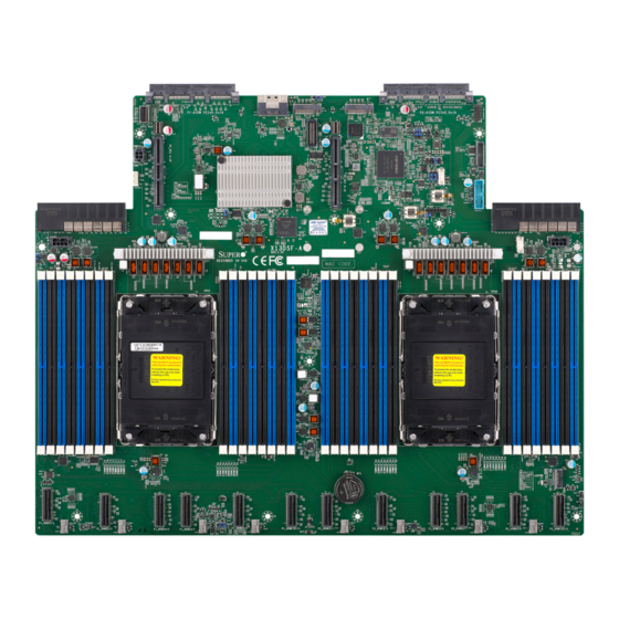
If anything listed is damaged or missing, please contact your retailer. 1.1 Checklist This motherboard is intended to be used in a Supermicro proprietary server as a part of an integrated solution. It will not be shipped as a standard, independent product. There will be no shipping package provided for this motherboard. - Page 9 Chapter 1: Introduction X13DSF-A Motherboard Image Note: All graphics shown in this manual were based upon the latest PCB revision available at the time of publication of the manual. The motherboard you received may or may not look exactly the same as the graphics shown in this manual.
- Page 10 Super X13DSF-A User's Manual X13DSF-A Motherboard Layout (not drawn to scale) P2-AIOM PCIe 5.0 x16 (J7) P1-AIOM PCIe 5.0x16 (J139) JTPM1 SATA 0~3 (JS1) M.2-H1 M.2-H2 JSB1 JPW3 JNCSI1 JIPMB1 JRK1 LEDBMC USB2/3 (3.0) MT1_1 MT1_2 JBT1 PSU1 PSU2 CPLD...
- Page 11 LEDBMC USB2/3 (3.0) MT1_1 MT1_2 PSU1 JBT1 PSU2 PSU1 PSU2 CPLD BIOS LICENSE JPW1 JPW2 JPW2 MT2_1 MT2_2 X13DSF-A MAC CODE JPW1 REV:1.01 BAR CODE DESIGNED IN USA MAC CODE CPU2 CPU1 JFP1 JFP1 P2_NVME0/1 LEDPWR P1_NVME0/1 LEDPWR P1_NVME10/11 P1_NVME2/3...
- Page 12 MT1_1, MT2_1: M.2-H1 Mounting Holes; MT1_2, MT2_2 MT1_2, MT2_2: M.2-H2 Mounting Holes P1-AIOM (J139), Supermicro Advanced Input/Output Module (AIOM) PCIe 5.0 x16 Connectors for rear I/O P2-AIOM (J7) support (OCP 3.0 SFF compliant) P1_NVME0/1 – Six PCIe 5.0 x8 MCIO Connectors supported by CPU1 P1_NVME10/11 P2_NVME0/1 –...
- Page 13 JPW3 JNCSI1 JIPMB1 JRK1 LEDBMC USB2/3 (3.0) MT1_1 MT1_2 JBT1 PSU1 PSU2 CPLD BIOS LICENSE JPW2 MT2_1 MT2_2 X13DSF-A JPW1 MAC CODE REV:1.01 BAR CODE DESIGNED IN USA MAC CODE CPU2 CPU1 JFP1 P2_NVME0/1 P1_NVME0/1 LEDPWR P1_NVME10/11 P1_NVME2/3 P2_NVME2/3 P2_NVME4/5 P2_NVME6/7...
- Page 14 One SlimSAS connector with SATA ports 0~3, located at JS1, supports RAID 0, RAID 1, RAID 5, and RAID 10 • One serial port header (COM1) and one VGA port (VGA) on the Supermicro AOM-DSF-IO rear I/O module Peripheral Devices •...
- Page 15 Chapter 1: Introduction BIOS • AMI SPI BIOS • EFI GUI, SPI dual/quad speed control, riser card auto detection support, Real Time Clock (RTC) wakeup, IPMIView, SMCIPMITOOL, IPMI CFG, SuperDoctor® 5, SD3 (for Windows OS), Redundant power supply unit detection, SPM, SUM-OOB/InBand Power Management •...
- Page 16 Note 1: The CPU maximum thermal design power (TDP) is subject to chassis and heatsink cooling restrictions. For proper thermal management, please check the chas- sis and heatsink specifications. Note 2: For BMC configuration instructions, please refer to the Embedded BMC Con- figuration User's Guide available at https://www.supermicro.com/support/manuals/.
- Page 17 Chapter 1: Introduction X13DSF-A REAR RJ45 JLAN1 Dedicated LAN Dedicated LAN RTL8211F U126 eMMC REAR USB CONN eMMC PE[13] JCOM1 COM CONN USB3.0/2.0 USB2.0 JUSB3 REAR USB3[0,1] [8,9] USB2[4,5] JVGA1 VGA CONN eSPI REAR AST2600A3 JTPM1 USB Header JUSB2 USB3[2,3]...
-
Page 18: Aom-Dsf-Io Image And Layout
Super X13DSF-A User's Manual 1.2 AOM-DSF-IO Image and Layout The Supermicro AOM-DSF-IO rear I/O module is used for rear I/O support for this motherboard. AOM-DSF-IO Image AOM-DSF-IO Layout (not drawn to scale) USB0/1 (3.0) DESIGNED IN USA BMC_LAN AOM-DSF-IO JSB2 REV:1.00... - Page 19 Chapter 1: Introduction AOM-DSF-IO Major Components Description Status LED1 Unit Identifier (UID) LED Solid Blue: Unit Identified Connector Description BMC_LAN Dedicated BMC LAN Port (RJ45) COM1 COM Header JSB2 I/O Module Connector used to connect to the motherboard JUIDB1 Unit Identifier (UID) Switch / BMC Reset Button USB0, USB1 (3.0) USB Ports (USB 3.0) VGA Port...
-
Page 20: Processor And Chipset Support
1.3 Processor and Chipset Support Built upon the functionality and capability of the 4th Gen. Intel Xeon Scalable Processors (Socket E LGA 4677) and the Intel C741 chipset, the X13DSF-A motherboard offers critical, pivotal technological breakthroughs that unleash unprecedented computing capabilities and... -
Page 21: Special Features
System Health sensors monitor temperatures and voltage settings of onboard processors and the system in real time via the BMC interface. Whenever the temperature of the CPU or the system exceeds Supermicro’s pre-defined threshold, the system and CPU cooling fan speed will increase to prevent the CPU or system from overheating. -
Page 22: Acpi Features
1.8 Serial Port The X13DSF-A motherboard supports one serial communication connection via the Supermicro AOM-DSF-IO rear I/O module. COM1 header on the AOM-DSF-IO can be used for input/output. The UART provides legacy speeds with a baud rate of up to 115.2 Kbps. -
Page 23: Chapter 2 Installation
Chapter 2: Installation Chapter 2 Installation 2.1 Static-Sensitive Devices Electrostatic Discharge (ESD) can damage electronic components. To avoid damaging your motherboard, it is important to handle it very carefully. The following measures are generally sufficient to protect your equipment from ESD. Precautions •... -
Page 24: Processor And Heatsink Installation
Thermal grease is pre-applied on a new heatsink. No additional thermal grease is needed. • Refer to the Supermicro website for updates on processor and memory support. • All graphics in this manual are for illustrations only. Your components may look different. - Page 25 Chapter 2: Installation 1. The 4th Gen. Intel Xeon Scalable Processor Processor Top View SP XCC SP MCC CPU Key CPU Key Pin 1 Pin 1 = Cutout = Pin 1 = CPU Key = Cutout = Pin 1 = CPU Key...
- Page 26 Super X13DSF-A User's Manual 2. The Processor Carrier Carrier E1B Carrier E1A Pin 1 Pin 1 Carrier Top View Carrier Bottom View = Cutout = Pin 1 = CPU Key = Cutout = Pin 1 = CPU Key...
- Page 27 Chapter 2: Installation 3. Heatsink 1U Heatsink 2U Heatsink Note: Exercise extreme care when handling the heatsink. Pay attention to the edges of heatsink fins, which can be sharp! To avoid damaging the heatsink, please do not apply excessive force on the fins.
- Page 28 Super X13DSF-A User's Manual Overview of the CPU Socket The CPU socket is protected by a plastic protective cover. Plastic Protective Cover CPU Socket...
- Page 29 Chapter 2: Installation Overview of the Processor Carrier Assembly The processor carrier assembly contains a 4th Gen. Intel Xeon Scalable processor and a processor carrier. Carefully follow the instructions given in the installation section to place a processor into the carrier to create a processor carrier assembly. The processor carrier assembly includes a processor and a carrier as shown below.
- Page 30 Super X13DSF-A User's Manual Overview of the Processor Heatsink Module (PHM) with SP XCC and Carrier E1A The Processor Heatsink Module (PHM) contains a heatsink, a processor carrier, and a 4th Gen. Intel Xeon Scalable processor. 1. Heatsink 1U Heatsink...
- Page 31 Chapter 2: Installation Overview of the Processor Heatsink Module (PHM) with SP MCC and Carrier E1B The Processor Heatsink Module (PHM) contains a heatsink, a processor carrier, and a 4th Gen. Intel Xeon Scalable processor. 1. Heatsink 1U Heatsink 2U Heatsink (Bottom View) (Bottom View) 2.
- Page 32 Super X13DSF-A User's Manual Creating the Processor Carrier Assembly The processor carrier assembly contains a 4th Gen. Intel Xeon Scalable processor and a processor carrier. To create the processor carrier assembly, please follow the steps below: Note: Before installation, be sure to follow the instructions given on pages 1 and 2 of this chapter to properly prepare for installation.
- Page 33 Chapter 2: Installation 2. First, turn over the processor carrier and locate Pin 1 on the CPU and Pin 1 on the carrier. Then, turn the processor over with component side (including the gold contacts) facing up and locate CPU keys on the processor. Finally, locate the CPU keys and four latches on the carrier as shown below.
- Page 34 Super X13DSF-A User's Manual 3. Locate the lever on the CPU socket and press it down as shown below. Lever Lever Carrier E1A Carrier E1B 4. Using Pin 1 as a guide, carefully align the CPU keys (marked A and B) on the processor against the CPU keys on the carrier (marked a and b) as shown below.
- Page 35 Chapter 2: Installation 6. After the processor is placed inside the carrier, examine the four sides of the processor, making sure that the processor is properly seated on the carrier. Processor Carrier Assembly Processor Carrier Assembly (Top View) (Component Side) SP XCC SP MCC...
- Page 36 Super X13DSF-A User's Manual Creating the PHM After creating the processor carrier assembly, please follow the instructions below to mount the processor carrier into the heatsink to form the PHM. Note: If this is a new heatsink, the thermal grease has been pre-applied on the un- derside.
- Page 37 Chapter 2: Installation Creating the PHM (1U Heatsink) Processor Carrier Assembly Processor Carrier Assembly (Component Side) (Component Side) (SP XCC, Carrier E1A) (SP MCC, Carrier E1B) Pin 1 Pin 1 Heatsink (Bottom Side) Heatsink (Bottom Side) PHM (Top View) PHM (1U Heatsink)
- Page 38 Super X13DSF-A User's Manual Creating the PHM (2U Heatsink) Processor Carrier Assembly Processor Carrier Assembly (Component Side) (Component Side) (SP XCC, Carrier E1A) (SP MCC, Carrier E1B) Pin 1 Pin 1 Heatsink (Bottom Side) Heatsink (Bottom Side) PHM (Top View)
- Page 39 Chapter 2: Installation Preparing the CPU Socket for Installation This motherboard comes with a plastic protective cover installed on the CPU socket. Remove it from the socket by following the instructions below. 1. Press the tabs inward. 2. Pull up the protective cover from the socket.
- Page 40 Super X13DSF-A User's Manual Preparing to Install the PHM into the CPU Socket After assembling the Processor Heatsink Module (PHM), you are ready to install it into the CPU socket. To ensure the proper installation, please follow the procedures below.
- Page 41 Chapter 2: Installation 2. Locate four peek nuts (marked A, B, C, D) and four rotating wires (marked 1, 2, 3, 4) on the heatsink as shown below. 1U Heatsink (Top Side) A, B, C, D: Peek Nut Rotating Wire 1, 2, 3, 4: Rotating Wire a, b, c, d: Threaded Fastener Rotating Wire...
- Page 42 Super X13DSF-A User's Manual 3. Check the rotating wires (marked 1, 2, 3, 4) to make sure that they are at unlatched positions as shown below before installing the PHM into the CPU socket. Unlatched State Top View Side View...
- Page 43 Chapter 2: Installation Installing the PHM into the CPU Socket 1. Align peek nut (marked A) on the heatsink against threaded fastener (marked a) on the CPU socket. Then align peek nuts (marked B, C, D) on the heatsink against threaded fasteners (marked b, c, d) on the CPU socket, making sure that all peek nuts on the heatsink are properly aligned with the correspondent threaded fasteners on the CPU socket.
- Page 44 Super X13DSF-A User's Manual 3. Press all four rotating wires outwards and make sure that the heatsink is securely latched onto the CPU socket. Latched State 1U Heatsink Latched State 2U Heatsink...
- Page 45 Chapter 2: Installation 4. With a T30 screwdriver, tighten all peek nuts in the sequence of A, B, C, and D with even pressure. To avoid damaging the processor or socket, do not use excessive force when tightening the peek nuts. (For best durability, 8in-lbf torque is recommended.) 5.
- Page 46 Super X13DSF-A User's Manual Removing the PHM from the CPU Socket Before removing the PHM from the motherboard, be sure to shut down the system and unplug the power cables from the power supply. Then follow the steps below. 1. Use a T30 screwdriver to loosen the four peek nuts on the heatsink in the sequence of A, B, C, and D.
- Page 47 Chapter 2: Installation 2. Once the peek nuts are loosened from the CPU socket, press the rotating wires inwards to unlatch the PHM from the socket as shown below. Unlatched State 1U Heatsink Unlatched State 2U Heatsink...
- Page 48 Super X13DSF-A User's Manual 3. Gently pull the PHM upwards to remove it from the CPU socket. 1U Heatsink 2U Heatsink...
- Page 49 Chapter 2: Installation Removing the Processor Carrier Assembly from the PHM To remove the processor carrier assembly from the PHM, please follow the steps below. 1. Detach the four plastic clips (marked a, b, c, d) on the processor carrier assembly from the four corners of the heatsink (marked A, B, C, D) as shown below.
- Page 50 Super X13DSF-A User's Manual 2. When all plastic clips are detached from the heatsink, remove the processor carrier assembly from the heatsink. SP XCC SP MCC 1U Heatsink (Bottom View) SP XCC SP MCC 2U Heatsink (Bottom View)
- Page 51 Chapter 2: Installation Removing the Processor from the Processor Carrier Assembly Once you have removed the processor carrier assembly from the PHM, you are ready to remove the processor from the processor carrier by following the steps below. 1. Unlock the lever from its locked position and push the lever upwards to disengage the processor from the processor carrier as shown in the drawings on the right below.
-
Page 52: Motherboard Installation
Super X13DSF-A User's Manual 2.3 Motherboard Installation All motherboards have standard mounting holes to fit different types of chassis. Make sure that the locations of all the mounting holes for both the motherboard and the chassis match. Although a chassis may have both plastic and metal mounting fasteners, metal ones are highly recommended because they ground the motherboard to the chassis. - Page 53 Chapter 2: Installation Installing the Motherboard 1. Install the I/O shield into the back of the chassis, if applicable. 2. Locate the mounting holes on the motherboard. See the previous page for the location. 3. Locate the matching mounting holes on the chassis. Align the mounting holes on the motherboard against the mounting holes on the chassis.
-
Page 54: Memory Support And Installation
Super X13DSF-A User's Manual 2.4 Memory Support and Installation Note: Check the Supermicro website for recommended memory modules. Important: Exercise extreme care when installing or removing memory modules to prevent any possible damage. Memory Support This motherboard supports up to 8TB memory capacity with 32 DIMMs of 256Gb 3DS RDIMM/ RDIMM DDR5 ECC memory. - Page 55 Chapter 2: Installation Memory Population for the X13DSF-A Motherboard (with 32 DIMM Slots) DDR5 Memory Population Table for the X13DSF-A Motherboard (with 32 DIMM Slots) 1 CPU: Memory Population Sequence 1 CPU & 1 DIMM P1-DIMMA1 or P1-DIMME1 or P1-DIMMB1 or P1-DIMMF1 P1-DIMMA1/P1-DIMMG1 1 CPU &...
- Page 56 Super X13DSF-A User's Manual DIMM Installation P2-AIOM PCIe 5.0 x16 (J7) P1-AIOM PCIe 5.0x16 (J139) SATA 0~3 (JS1) JTPM1 1. Insert the desired number of DIMMs into the memory M.2-H1 JSB1 M.2-H2 JPW3 JNCSI1 slots based on the recommended DIMM population tables...
-
Page 57: Rear I/O Connectors
Refer to the layout below for the locations of P1-AIOM (J139) and P2-AIOM (J7). Rear I/O Module Connector An Supermicro proprietary rear I/O module connector is located at JSB1 on the motherboard. This connector provides support for rear I/O module connection. Refer to the layout below for the location of JSB1. -
Page 58: Connectors/Ports On The Aom-Dsf-Io
Super X13DSF-A User's Manual 2.6 Connectors/Ports on the AOM-DSF-IO BMC LAN Port A dedicated BMC LAN port (BMC_LAN) is located on the AOM-DSF-IO. The dedicated BMC LAN port provides LAN support for the Baseboard Management Controller (BMC). Connect an RJ45 cable to this LAN port for BMC LAN support. Please refer to Section 2.10 (page 82) for LAN LED information. - Page 59 UID can also be triggered via BMC on the motherboard. For more details on the UID LEDs and BMC LEDs, refer to the tables below. Also, refer to the BMC User's Guide posted on our website at https://www.supermicro.com for more information on BMC. UID/BMC Reset Switch (JUIDB1) Features &...
- Page 60 Super X13DSF-A User's Manual USB0/1 (3.0) DESIGNED IN USA BMC_LAN AOM-DSF-IO JSB2 REV:1.00 COM1 JFP1 1. UID / BMC Reset Switch (JUIDB1) Power Button 2. Rear UID LED (LED1) Reset/UID Button UID LED_N 3. Front UID LED (Pin 3/Pin 4 of JFP1)
- Page 61 Chapter 2: Installation Universal Serial Bus (USB) Ports There are two USB 3.0 ports (USB0, USB1) on the AOM-DSF-IO. These USB ports can be used for USB support via USB cables (not included). VGA Connections There is one VGA connection in your system. The rear VGA connection is located at VGA on the AOM-DSF-IO.
-
Page 62: Front Control Panel
JFP1, contains header pins for various buttons and LED indications with I²C support for front access. This front control panel header is designed specifically for use with Supermicro chassis. Refer to the figure below for the pin-out descriptions for JFP1. P1-AIOM PCIe 5.0x16 (J139) P2-AIOM PCIe 5.0 x16 (J7) - Page 63 Chapter 2: Installation Front Control Panel LEDs Front Control Panel (JFP1) LED Indicators Event Power Information Power Fail Power On Solid On HDD Activity Blinking NIC Activity Blinking Overheat Solid On Fan Fail Blinking at 1Hz Power Fail Blinking at 1/4Hz Solid On Local UID On Solid On...
- Page 64 Super X13DSF-A User's Manual Power On and BMC/BIOS Status LED Button The Power On and BMC/BIOS Status LED button is located on Pin 1 of the front control panel header located at JFP1. Momentarily contacting Pin 1 of JFP1 will power on/off the system or display BMC/BIOS status.
- Page 65 Chapter 2: Installation UID LED The unit identifier LED connection is located on Pin 3 of JFP1. Refer to the figure below for more information on JFP1. Fail LED (Information LED for OH/FF/PF) The Fail LED (Information LED for OH/Fan Fail/PWR Fail) connection is located on Pin 4 of JFP1.
- Page 66 Super X13DSF-A User's Manual LAN1/LAN2 (NIC1/NIC2) The Network Interface Controller (NIC) LED connection for LAN Port 1 is located on Pin 6 of JFP1, and LAN Port 2 is on Pin 5. Refer to the table below. LAN1/LAN2 LED LED States...
- Page 67 Chapter 2: Installation Standby Power LED The LED indicator for standby power is located on Pin 8 of JFP1. If this LED is on, standby power is on. RoT (Root of Trust) Power LED The Power LED for Root of Trust (RoT) connection is located on Pin 9 of JFP1. If this LED is on, power for the RoT chip is on.
- Page 68 Super X13DSF-A User's Manual Standby Power A Standby Power (I C) connection is located on Pin 10 - Pin 14 of JFP1 to provide power to the system when it is in standby mode. Refer to the table below for pin definitions.
- Page 69 Chapter 2: Installation FP Power Front Panel power connections are located on Pin 16 - Pin 18 of JFP1 to provide power to your system. Refer to the table below for pin definitions. FP PWR Pin Definitions Pin# Definition +5V PWR JFP1 Power Button Reset/UID Button...
-
Page 70: Connectors And Headers
Super X13DSF-A User's Manual 2.8 Connectors and Headers Power Connections Power Supply Connectors Two power supply connectors, located at PSU1/PSU2, provide main power to your system. The two 8-pin power connectors (JPW1, JPW2) and one 4-pin power connector (JPW3) provide additional power for system use. All these power connectors meet the ATX SSI EPS 12V specification and must be connected to your power supply to provide adequate power to your system. - Page 71 LEDBMC 4. FAN4 USB2/3 (3.0) MT1_1 MT1_2 JBT1 PSU1 PSU2 CPLD BIOS LICENSE 5. FAN5 JPW2 MT2_1 MT2_2 X13DSF-A MAC CODE JPW1 REV:1.01 BAR CODE DESIGNED IN USA MAC CODE 6. FAN6 CPU2 CPU1 7. FAN7 8. FAN8 JFP1 P2_NVME0/1...
- Page 72 The JTPM1 header is used to connect a Trusted Platform Module (TPM)/Port 80, which is available from Supermicro (optional). A TPM/Port 80 connector is a security device that supports encryption and authentication in hard drives. It allows the motherboard to deny access if the TPM, which is associated with the hard drive, is not installed in the system.
- Page 73 JPW3 JNCSI1 JIPMB1 JRK1 LEDBMC USB2/3 (3.0) MT1_1 MT1_2 JBT1 PSU1 PSU2 CPLD BIOS LICENSE JPW2 MT2_1 MT2_2 X13DSF-A MAC CODE JPW1 REV:1.01 BAR CODE DESIGNED IN USA MAC CODE CPU2 CPU1 JFP1 P2_NVME0/1 P1_NVME0/1 LEDPWR P1_NVME10/11 P1_NVME2/3 P1_NVME8/9 P2_NVME2/3...
- Page 74 Super X13DSF-A User's Manual Chassis Intrusion A Chassis Intrusion header is located at JL1 on the motherboard. Attach the appropriate cable from the chassis to inform you when the chassis is opened. Refer to the table below for pin definitions.
- Page 75 3. SATA 0~3 (JS1) JIPMB1 JRK1 LEDBMC USB2/3 (3.0) MT1_1 MT1_2 JBT1 PSU1 PSU2 CPLD BIOS LICENSE JPW2 MT2_1 MT2_2 X13DSF-A MAC CODE JPW1 REV:1.01 BAR CODE DESIGNED IN USA MAC CODE CPU2 CPU1 JFP1 P2_NVME0/1 P1_NVME0/1 LEDPWR P1_NVME10/11 P1_NVME2/3...
- Page 76 Super X13DSF-A User's Manual MCIO NVMe Connectors Twelve MCIO NVMe connectors, located at P1_NVME0/1 - P1_NVME10/11 (supported by CPU1) and P2_NVME0/1 - P2_NVME10/11 (supported by CPU2), provide 24 NVMe PCIe 5.0 x4 connections on the motherboard. Use these MCIO connectors to support high-speed PCIe NVMe storage devices.
- Page 77 JPW3 JNCSI1 JIPMB1 JRK1 LEDBMC USB2/3 (3.0) MT1_1 MT1_2 JBT1 PSU1 PSU2 CPLD BIOS LICENSE JPW2 MT2_1 MT2_2 X13DSF-A MAC CODE JPW1 REV:1.01 BAR CODE DESIGNED IN USA MAC CODE CPU2 CPU1 JFP1 P2_NVME0/1 P1_NVME0/1 LEDPWR P1_NVME10/11 P1_NVME2/3 P1_NVME8/9 P2_NVME2/3...
- Page 78 Super X13DSF-A User's Manual VROC RAID Key Header An Intel VROC RAID Key header is located at JRK1 on the motherboard. Install a VROC RAID Key on JRK1 for NVMe RAID support as shown in the illustration below. Please refer to the layout below for the location of JRK1.
-
Page 79: Jumper Settings
Chapter 2: Installation 2.9 Jumper Settings How Jumpers Work To modify the operation of the motherboard, jumpers can be used to choose between optional settings. Jumpers create shorts between two pins to change the function of the connector. Pin 1 is identified with a square solder pad on the printed circuit board. See the diagram below for an example of jumping pins 1 and 2. - Page 80 Super X13DSF-A User's Manual CMOS Clear JBT1 is used to clear CMOS, which will also clear any passwords. Instead of pins, this jumper consists of contact pads to prevent accidentally clearing the contents of CMOS. To Clear CMOS 1. First power down the system and unplug the power cord(s).
- Page 81 JPW3 JNCSI1 JIPMB1 JRK1 LEDBMC USB2/3 (3.0) MT1_1 MT1_2 JBT1 PSU1 PSU2 CPLD BIOS LICENSE JPW2 MT2_1 MT2_2 X13DSF-A MAC CODE JPW1 REV:1.01 BAR CODE DESIGNED IN USA MAC CODE CPU2 CPU1 JFP1 P2_NVME0/1 P1_NVME0/1 LEDPWR P1_NVME10/11 P1_NVME2/3 P1_NVME8/9 P2_NVME2/3...
-
Page 82: Led Indicators
Super X13DSF-A User's Manual 2.10 LED Indicators BMC Heartbeat LED A BMC Heartbeat LED is located at LEDBMC on the motherboard. When LEDBMC is blinking green, the BMC is functioning normally. Refer to the layout below for the location of LEDBMC. - Page 83 Chapter 2: Installation BMC LAN LEDs The AOM-DSF-IO provides a dedicated BMC LAN connection. The LED on the right side of the BMC LAN port indicates activity, and the LED on the left indicates the speed of the connection. Refer to the table below for more information. LAN 1/LAN 2 BMC_LAN BMC LAN LEDs...
-
Page 84: Chapter 3 Troubleshooting
Super X13DSF-A User's Manual Chapter 3 Troubleshooting 3.1 Troubleshooting Procedures Use the following procedures to troubleshoot your system. If you have followed all of the procedures below and still need assistance, refer to the ‘Technical Support Procedures’ and/ or ‘Returning Merchandise for Service’ section(s) in this chapter. Always disconnect the AC power cord before adding, changing or installing any non hot-swap hardware components. - Page 85 Chapter 3: Troubleshooting No Video 1. If the power is on, but you do not have video, remove all add-on cards and cables. 2. Remove all memory modules and turn on the system (if the alarm is on, check the specs of memory modules, reset the memory, or try a different one).
- Page 86 Super X13DSF-A User's Manual When the System Becomes Unstable A. If the system becomes unstable during or after OS installation, check the following: 1. CPU/BIOS support: Make sure that your CPU is supported and that you have the latest BIOS installed in your system.
-
Page 87: Technical Support Procedures
Before contacting Technical Support, please take the following steps. Also, please note that as a motherboard manufacturer, Supermicro also sells motherboards through its channels, so it is best to first check with your distributor or reseller for troubleshooting services. They should know of any possible problems with the specific system configuration that was sold to you. -
Page 88: Frequently Asked Questions
BIOS revision to make sure that it is newer than your BIOS before downloading. Note 1: The SPI BIOS chip used on this motherboard cannot be removed. Send your motherboard back to our RMA Department at Supermicro for repair. Note 2: For BIOS Update and Recovery instructions, please refer to the Firmware Update and Recovery Instructions for Supermicro's X13 motherboard user's manuals posted at https://www.supermicro.com/support/manuals/. -
Page 89: Battery Removal And Installation
Chapter 3: Troubleshooting 3.4 Battery Removal and Installation Battery Removal To remove the onboard battery, follow the steps below: 1. Power off your system and unplug your power cable. 2. Locate the onboard battery as shown below. 3. Using a tool such as a pen or a small screwdriver, push the battery lock outwards to unlock it. -
Page 90: Returning Merchandise For Service
Super X13DSF-A User's Manual 3.5 Returning Merchandise for Service A receipt or copy of your invoice marked with the date of purchase is required before any warranty service will be rendered. You can obtain service by calling your vendor for a Returned Merchandise Authorization (RMA) number. -
Page 91: Chapter 4 Uefi Bios
Chapter 4: UEFI BIOS Chapter 4 UEFI BIOS 4.1 Introduction This chapter describes the AMIBIOS™ Setup utility for the motherboard. The BIOS is stored on a chip and can be easily upgraded using the BMC WebUI or the SUM utility. Note: Due to periodic changes to the BIOS, some settings may have been added or deleted and might not yet be recorded in this manual. -
Page 92: Main Setup
Super X13DSF-A User's Manual 4.2 Main Setup When you first enter the AMI BIOS Setup utility, you will see the Main setup screen. You can always return to the Main setup screen by selecting the Main tab on the top of the screen. - Page 93 Chapter 4: UEFI BIOS Memory Information Total Memory This feature displays the total size of memory available in the system.
-
Page 94: Advanced Setup Configurations
Super X13DSF-A User's Manual 4.3 Advanced Setup Configurations Use the arrow keys to select the Advanced submenu and press <Enter> to access the submenu items: Warning: Take Caution when changing the Advanced settings. An incorrect value, an improper DRAM frequency, or a wrong BIOS timing setting may cause the system to malfunction. When this occurs, restore the setting to the manufacturer default setting. - Page 95 DCMS-SINGLE) is Supermicro’s Data Center Management Suite license that enables server node to take full advantage of Supermicro Management Software and Utilities features. Contact us for more information. Note 2: Refer to the submenu of Security -> Supermicro Security Erase Configuration to set "Lockdown Mode".
- Page 96 Super X13DSF-A User's Manual Rear USB Port(s) (Available when "Lockdown Mode" is set to Enabled with the DCMS key) Select Enabled to allow the specific type of USB devices to be used in the rear USB ports. Select Enabled (Dynamic) to allow or disallow this particular type of USB devices to be used in the rear USB ports without rebooting the system.
- Page 97 Chapter 4: UEFI BIOS Processor Configuration The following CPU information is displayed: • Processor BSP Revision • Processor Socket • Processor ID • Processor Frequency • Processor Max Ratio • Processor Min Ratio • Microcode Revision • L1 Cache RAM (Per Core) •...
- Page 98 Super X13DSF-A User's Manual potential; however, this may consume maximal amount of power as energy is needed to fuel processor operation. Select Performance to enhance system performance; however, this may consume more power as energy is needed to fuel the processors for operation.
- Page 99 Chapter 4: UEFI BIOS The following information is displayed when "SpeedStep (P-States)" is set to Enable: • SST-PP Level • Capable • Core Count • P1 Ration • Package TDP (W) • DTS_Max Activate SST-BF (Available when your CPU supports the Intel Speed Select function) Select Enable for Intel Speed Select Technology-Base Frequency support.
- Page 100 Super X13DSF-A User's Manual CPU Flex Ratio Override (Available when "SpeedStep (P-States)" is set to Enable and when your CPU supports this feature) Select Enable to override the CPU Flex-Ratio setting, which is the minimum multiplier that allows the computer to clock. The options are Disable and Enable.
- Page 101 Chapter 4: UEFI BIOS CPU C6 Report Select Enable to allow the BIOS to report the CPU C6 State (ACPI C3) to the operating system. During the CPU C6 State, the power to all cache is turned off. The options are Disable, Enable, and Auto.
- Page 102 Super X13DSF-A User's Manual DCU Streamer Prefetcher If this feature is set to Enable, the Data Cache Unit (DCU) streamer prefetcher will prefetch data streams from the cache memory to the DCU to speed up data accessing and processing to enhance CPU performance. The options are Enable and Disable.
- Page 103 Chapter 4: UEFI BIOS Limit CPU PA to 46 Bits Select Enable to limit CPU physical address to 46 bits to support the older Hyper-V platform. The options are Disable and Enable. ---------------------------------------------------------------- TME, TME-MT, TDX ---------------------------------------------------------------- Memory Encryption (TME) (Available when your CPU supports Intel TME) Select Enabled for Intel Total Memory Encryption (TME) support to enhance memory data security.
- Page 104 Super X13DSF-A User's Manual ---------------------------------------------------------------- Software Guard Extension (SGX) ---------------------------------------------------------------- *The following SGX features are available when "Memory Encryption (TME)" is set to Enabled and when your CPU supports Intel SGX. Note: Each memory channel must have at least one DIMM populated on the mother- board to support the Intel SGX features.
- Page 105 Chapter 4: UEFI BIOS Software Guard Extensions Epoch 0 (Available when "SW Guard Extensions (SGX)" is set to Enabled and "Select Owner EPOCH input type" is set to Manual User Defined Owner EPOCHs) Use this feature to enter the EPOCH value. The default is 0. Software Guard Extensions Epoch 1 (Available when "SW Guard Extensions (SGX)"...
- Page 106 Super X13DSF-A User's Manual Chipset Configuration Warning: Setting the wrong values in the following features may cause the system to malfunc- tion. North Bridge This feature allows you to configure the following North Bridge settings. Uncore Configuration The following information is displayed.
- Page 107 Chapter 4: UEFI BIOS Link L1 Enable Select Enable for the BIOS to activate Link L1 support which will power down the UPI links to save power when the system is idle. This feature is available for the system that uses Intel processors with UPI technology support.
- Page 108 Super X13DSF-A User's Manual only snoop misses. That way, subsequent reads to the line will encounter it in the S state and will not have to snoop, saving the latency and snoop bandwidth. Stale "AtoS" may be beneficial in a workload where there are many cross-socket reads. The options are Disable, Enable, and Auto.
- Page 109 Chapter 4: UEFI BIOS DDR 2X Refresh Enable Select Enable for memory 2X refresh support to enhance memory performance. The options are Auto, Disable, and Enable. CXL Type 3 Legacy Select Enable to use the CXL Type 3 memory device, which can be supported by the CXL Type 2 flows, for memory bandwidth and capacity expansion.
- Page 110 Super X13DSF-A User's Manual Correctable Error Threshold Use this feature to specify the threshold value for correctable memory-error logging, which sets a limit on the maximum number of events that can be logged in the memory error log at a given time. The default setting is 512.
- Page 111 Chapter 4: UEFI BIOS Enhanced PPR Use this feature to set advanced memory test. Select Enabled to always execute for every boot. Select Once to execute only one time. The options are Disabled, Enabled, and Once. Memory PFA Support (Available when the DCMS key is activated) Select Enabled to enable memory Predictive Failure Analysis (PFA) support.
- Page 112 Super X13DSF-A User's Manual Onboard NVMe0 / Onboard NVMe1 / Onboard NVMe2 / Onboard NVMe3 / Onboard NVMe4 / Onboard NVMe5 / Onboard NVMe6 / Onboard NVMe7 / Onboard NVMe8 / Onboard NVMe9 / Onboard NVMe10 / Onboard NVMe11 / P1-AIOM PCIe 5.0x16 / P1_PE1 0-15 / P2- AIOM PCIe 5.0x16 / P2_PE1 0-15...
- Page 113 Chapter 4: UEFI BIOS Intel VT for Directed I/O (VT-d) Intel VT for Directed I/O (VT-d) Select Enable to use Intel Virtualization Technology for Direct I/O VT-d support by reporting the I/O device assignments to the Virtual Machine Monitor (VMM) through the DMAR ACPI tables.
- Page 114 Super X13DSF-A User's Manual Intel VMD for Volume Management Device on Socket 0 (Available when "NVMe Mode Switch" is set to Manual) VMD Config for PCH ports Enable/Disable VMD Select Enable to enable the Intel Volume Management Device (VMD) technology support for the root port specified.
- Page 115 Chapter 4: UEFI BIOS Intel VMD for Volume Management Device on Socket 1 (Available when "NVMe Mode Switch" is set to Manual) VMD Config for IOU 0 / VMD Config for IOU 1 / VMD Config for IOU 2 / VMD Config for IOU 3 / VMD Config for IOU 4 Enable/Disable VMD Select Enable to enable the Intel VMD technology support for the root port specified.
- Page 116 Super X13DSF-A User's Manual IIO eDPC Support (Available when your system supports this feature) Use this feature to configure the setting for IIO Enhanced Downstream Port Containment (eDPC) support for your system in an effort to improve the error containment capacity within the PCIe subsystem when an uncorrected error is detected either at the root port or at the switch downstream port.
- Page 117 Chapter 4: UEFI BIOS South Bridge The following information is displayed: • USB Devices: Legacy USB Support Select Enabled to support onboard legacy USB devices. Select Auto to disable legacy support if there are no legacy USB devices present. Select Disabled to have all USB devices available for EFI applications only.
- Page 118 Super X13DSF-A User's Manual PCH SATA0 Configuration / PCH SATA1 Configuration / SATA2 Configuration When this submenu is selected, the AMI BIOS automatically detects the presence of the SATA devices that are supported by the Intel PCH chip and displays the following features.
- Page 119 Chapter 4: UEFI BIOS SATA Device Type Use this feature to specify if the device installed on the SATA port specified by the user should be connected to a solid state drive or a hard disk drive. The options are Hard Disk Drive and Solid State Drive.
- Page 120 Disabled and Enabled. Supermicro BIOS-Based TPM Provision Support If this feature is set to Enabled, Supermicro BIOS-based TPM provision will be supported. The options are Disabled and Enabled. Note: Enabling this feature will lock your TPM on the production platform, and you will...
- Page 121 Note 1: If this feature is set to Enabled, be sure to disable Device Function On-Hide (EV DFX) support when it is present in the BIOS for the system to work properly. Note 2: For more information on TPM, please refer to the TPM manual at https://www. supermicro.com/manuals/other/AOM-TPM-9670V_9670H.pdf. ACPI Settings NUMA Use this feature to enable Non-Uniform Memory Access (NUMA) to enhance system performance.
- Page 122 Super X13DSF-A User's Manual Serial Port 1 Configuration Serial Port 1 Select Enabled to enable serial port 1. The options are Disabled and Enabled. Device Settings (Available when "Serial Port 1" is set to Enabled) This feature displays the base I/O port address and the Interrupt Request address of serial port 1.
- Page 123 Chapter 4: UEFI BIOS Serial Port Console Redirection COM1 (Available when your system supports serial port of COM1) Console Redirection Select Enabled to enable COM port 1 for Console Redirection, which allows a client machine to be connected to a host machine at a remote site for networking. The options are Disabled and Enabled.
- Page 124 Super X13DSF-A User's Manual Flow Control Use this feature to set the flow control for Console Redirection to prevent data loss caused by buffer overflow. Send a "Stop" signal to stop sending data when the receiving buffer is full. Send a "Start" signal to start sending data when the receiving buffer is empty. The options are None and Hardware RTS/CTS.
- Page 125 Chapter 4: UEFI BIOS Bits Per Second Use this feature to set the transmission speed for a serial port used in Console Redirection. Make sure that the same speed is used in the host computer and the client computer. A lower transmission speed may be required for long and busy lines.
- Page 126 Super X13DSF-A User's Manual Putty KeyPad This feature selects Function Keys and KeyPad settings for Putty, which is a terminal emulator designed for the Windows OS. The options are VT100, LINUX, XTERMR6, SCO, ESCN, and VT400. Legacy Console Redirection Legacy Console Redirection Settings...
- Page 127 Chapter 4: UEFI BIOS Terminal Type EMS Use this feature to select the target terminal emulation type for Console Redirection. Select VT100 to use the ASCII character set. Select VT100+ to add color and function key support. Select ANSI to use the extended ASCII character set. Select VT-UTF8 to use UTF8 encoding to map Unicode characters into one or more bytes.
- Page 128 Super X13DSF-A User's Manual PXE Boot Wait Time (Available when "Network Stack" is set to Enabled) Use this feature to set the wait time (in seconds) upon which the system BIOS will wait for you to press the <ESC> key to abort PXE boot instead of proceeding with PXE boot by connecting to a network server immediately.
- Page 129 Chapter 4: UEFI BIOS New DNS address Use this feature to set the DNS server address for the local machine. Commit Changes and Exit Press <Enter> to save changes and exit. The options are Yes and No. Discard Changes and Exit Press <Enter>...
- Page 130 Super X13DSF-A User's Manual PCIe/PCI/PnP Configuration The following information is displayed: • PCI Bus Driver Version PCI Devices Common Settings: Above 4G Decoding (Available when the system supports 64-bit PCI decoding) Select Enabled to decode a PCI device that supports 64-bit in the space above 4G Address.
- Page 131 Chapter 4: UEFI BIOS NVMe Firmware Source Use this feature to select the NVMe firmware to support system boot. The options are Vendor Defined Firmware and AMI Native Support. The default option, Vendor Defined Firmware, is pre-installed on the drive and may resolve errata or enable innovative functions for the drive.
- Page 132 Super X13DSF-A User's Manual HTTPS Boot Checks Hostname Enable this feature for HTTPS boot to check the hostname of the TLS certificates to see if it matches the host name provided by the remote server. The options are Enabled and Disabled (WARNING: Security Risk!!).
- Page 133 Supermicro KMS TCP Port number Use this feature to set the TCP port number used in Supermicro KMS Server. The valid range is 100–9999. The default setting is 5696. Do not change the default setting unless a different TCP port number has been specified and used in the Supermicro KMS Server.
- Page 134 Super X13DSF-A User's Manual CA Certificate/ Client Certificate/ Client Private Key Use the three features to enroll factory defaults or load the KMS Transport Layer Security (TLS) certificates, which are generated by the KMS Server, from the file stored in the USB flash drive as shown below.
- Page 135 Chapter 4: UEFI BIOS Super-Guardians Configuration Press <Del> during system boot to enter the BIOS Setup utility. Navigate to the Advanced tab. Use the arrow keys to select Super-Guardians Configuration and press <Enter>.
- Page 136 Super X13DSF-A User's Manual Super-Guardians Protection Policy Use this feature to enable the Super-Guardians Protection Policy. The options are Storage, System, and System and Storage. The default setting is Storage. Set this feature to Storage to protect and have secure access to your storage devices (TCG NVMe devices) with the Authentication-Key (AK).
- Page 137 Note 1: Be sure that the KMS Server is ready before configuring this feature. Note 2: Use the professional KMS Server solutions (e.g., Thales Server) or the Supermicro PyKMIP Software Package to establish the KMS Server. KMS Server Retry Count (Available when "TPM Security Policy" and "USB Security Policy"...
- Page 138 Super X13DSF-A User's Manual TPM Security Policy (Available when "KMS Security Policy" and "USB Security Policy" are set to Disabled) The options are Disabled and Enabled. The default setting is Disabled. Set this feature to Enabled to enable the TPM Security Policy. Save settings (you can press <F4>) and reboot the system for changes to take effect.
- Page 139 Chapter 4: UEFI BIOS Load Authentication-Key (Available when "KMS Security Policy" and "TPM Security Policy" are set to Disabled) The options are Disabled and Enabled. The default setting is Disabled. Set this feature to Enabled; save settings (you can press <F4>) and reboot the system for changes to take effect. While booting, the BIOS will automatically load the Authentication-Key (filename: TPMAuth.
- Page 140 Super X13DSF-A User's Manual Save Authentication-Key (Available when "TPM Security Policy" is set to Enabled and "USB Security Policy" is set to Disabled) The options are Disabled and Enabled. The default setting is Disabled. Set this feature to Enabled; save settings (you can press <F4>) and reboot the system for changes to take effect.
- Page 141 Chapter 4: UEFI BIOS USB Security Policy (Available when "KMS Security Policy" and "TPM Security Policy" are set to Disabled) Use this feature to enable the USB Security Policy. The options are Disabled and Enabled. The default setting is Disabled. Set this feature to Enabled; save settings (you can press <F4>) and reboot the system for changes to take effect.
- Page 142 Super X13DSF-A User's Manual Intel(R) I350 Gigabit Network Connection - (MAC address) Note: The Ethernet controller and MAC addresses shown above are based on you system features. Firmware Image Properties The following information is displayed: • Option ROM version •...
- Page 143 Chapter 4: UEFI BIOS • MAC Address • Virtual MAC Address TLS Authenticate Configuration This submenu allows you to configure Transport Layer Security (TLS) settings. Server CA Configuration This feature allows you to configure the client certificate that is to be used by the server. Enroll Certification ...
- Page 144 Super X13DSF-A User's Manual Enroll Certification Using File This feature allows you to enroll the security certificate in the system by using a file. Certification GUID Press <Enter> and input the certification GUID. Commit Changes and Exit Use this feature to save all changes and exit TLS settings.
- Page 145 Chapter 4: UEFI BIOS Strip Size: Use this feature to select the RAID strip size. The options are 4KB, 8KB, 16KB, 32KB, 64KB, and 128KB. The available options are based on the setting of "RAID Level:" above. Capacity (GB): This feature allows you to enter the desired RAID capacity (in GB). Create RAID Volume Use this feature to create a RAID volume with the settings above.
- Page 146 Super X13DSF-A User's Manual Strip Size: Use this feature to select the RAID strip size. The options are 4KB, 8KB, 16KB, 32KB, 64KB, and 128KB. The available options are based on the setting of "RAID Level:" above. Capacity (GB): This feature allows you to enter the desired RAID capacity (in GB).
- Page 147 Chapter 4: UEFI BIOS Strip Size: Use this feature to select the RAID strip size. The options are 4KB, 8KB, 16KB, 32KB, 64KB, and 128KB. The available options are based on the setting of "RAID Level:" above. Capacity (GB): This feature allows you to enter the desired RAID capacity (in GB). Create RAID Volume Use this feature to create a RAID volume with the settings above.
- Page 148 Super X13DSF-A User's Manual Driver Health This feature displays the health information of the drivers installed in your system, including LAN controllers, as detected by the BIOS. Select one and press <Enter> to see the details. Note: This section is provided for reference only, for the driver health status will dif- fer depending on the drivers installed in your system.
-
Page 149: Event Logs
Chapter 4: UEFI BIOS 4.4 Event Logs Use this feature to configure Event Logs settings. Note: After you've made any changes in this section, please be sure to reboot the system for the changes to take effect. Change SMBIOS Event Log Settings Enabling/Disabling Options SMBIOS Event Log Select Enabled to enable System Management BIOS (SMBIOS) Event Logging during system... - Page 150 Super X13DSF-A User's Manual SMBIOS Event Log Standard Settings Log System Boot Event (Available when "SMBIOS Event Log" is set to Enabled) Select Enabled to log system boot events. The options are Enabled and Disabled. MECI (Available when "SMBIOS Event Log" is set to Enabled) Enter the increment value for the multiple event counter.
-
Page 151: Bmc
Chapter 4: UEFI BIOS 4.5 BMC Use this feature to configure BMC settings. BMC Firmware Revision This feature indicates the BMC firmware revision used in your system. BMC STATUS This feature indicates the status of the BMC firmware installed in your system. System Event Log Enabling/Disabling Options SEL Components... - Page 152 Super X13DSF-A User's Manual When SEL is Full (Available when "SEL Components" is set to Enabled) This feature allows you to determine what the BIOS should do when the system event log is full. Select Erase Immediately to erase all events in the log when the system event log is full.
- Page 153 Chapter 4: UEFI BIOS Station MAC Address (Available when "Configuration Address Source" is set to Static) This feature displays the Station MAC address for this computer. Mac addresses are six two-digit hexadecimal numbers. Gateway IP Address (Available when "Configuration Address Source" is set to Static) This feature displays the Gateway IP address for this computer.
- Page 154 Super X13DSF-A User's Manual Gateway IP (Available when "Configuration Address Source" is set to Static Configuration) Use this feature to enter the IPv6 gateway IP address. Press <Enter> to change the setting. Advanced Settings (Available when "Configuration Address Source" is set to DHCPv6 Stateless) Use this feature to set the DNS server IP.
-
Page 155: Security
BIOS Setup utility. The length of the password should be from three characters to 20 characters long. Note: For detailed instructions on how to configure Security Boot settings, please refer to the Security Boot Configuration User's Guide posted on the web page under the link: https://www.supermicro.com/support/manuals/. - Page 156 This section allows you to configure the Supermicro-proprietary Security Erase settings. When this section is selected, the following information is displayed. Please note that the order of the following information may differ based on the storage devices being detected.
- Page 157 New Password (Available when "Password" above has been set) Use this feature to set the new user password for the storage device which allows you to configure the Supermicro Security Erase settings by using this new user password. Lockdown Mode (Available when the DCMS key is activated)
- Page 158 Super X13DSF-A User's Manual Set User Password (Available when "Security Frozen:" above is No) Press <Enter> to set the HDD user password. Secure Boot Note: For detailed instructions on how to configure Security Boot settings, please refer to the Security Boot Configuration User's Guide posted on the web page under the link: https://www.supermicro.com/support/manuals/.
- Page 159 Chapter 4: UEFI BIOS Enter Deployed Mode / Exit Deployed Mode (Available when "Secure Boot Mode" is set to Custom) Select Ok to reset system to the User Mode or to the Deployed Mode. Key Management (Available when "Secure Boot Mode" is set to Custom) The following information is displayed.
- Page 160 Super X13DSF-A User's Manual Secure Boot variable / Size / Keys / Key Source Platform Key (PK) Use this feature to enter and configure a set of values to be used as platform firmware keys for the system. These values also indicate the sizes, keys numbers, and the sources of the authorized signatures.
- Page 161 Chapter 4: UEFI BIOS TCG Storage Security Configuration: (Storage Device Name) (Available when the storage device is compliant with TCG specifications) Select this device. Press <Enter> and the following information is displayed: • TCG Storage Security Password Description: • PASSWORD CONFIGURATION: •...
-
Page 162: Boot
Super X13DSF-A User's Manual 4.7 Boot Use this feature to configure Boot settings: Boot Mode Select Use this feature to select the type of devices from which the system will boot. The options are Legacy, UEFI, and Dual. Note: When "Boot Mode Select" is set to Dual, all OPROM-related features will be set to Legacy. - Page 163 Chapter 4: UEFI BIOS When "Boot Mode Select" is set to UEFI, the following features will be displayed for configuration: • Boot Option #1 ~ Boot Option #9 Add New Boot Option (Available when any storage device is detected by the BIOS) This feature allows you to add a new boot option to the boot priority features for system boot.
- Page 164 Super X13DSF-A User's Manual Hard Disk Drive BBS Priorities This feature allows you to set the system boot order of detected devices. USB Key Drive BBS Priorities This feature allows you to set the system boot order of detected devices.
-
Page 165: Save & Exit
Chapter 4: UEFI BIOS 4.8 Save & Exit Select Save & Exit from the BIOS Setup screen to configure the settings below. Save Options Discard Changes and Exit Use this feature to exit from the BIOS Setup utility without making any permanent changes to the system configuration and reboot the computer. - Page 166 Super X13DSF-A User's Manual Default Options Restore Optimized Defaults Select this feature and press <Enter> to load manufacturer optimized default settings which are intended for maximum system performance but not for maximum stability. Note: Please reboot the system for the changes to take effect to ensure that your system has the optimized default settings.
-
Page 167: Appendix A Bios Post Codes
When BIOS performs the Power On Self Test, it writes checkpoint codes to I/O port 0080h. If the computer cannot complete the boot process, a diagnostic card can be attached to the computer to read I/O port 0080h (Supermicro P/N AOM-SPI80-V). For information on AMI updates, please refer to https://www.ami.com/products/. -
Page 168: Appendix B Software
1. Create a method to access the Microsoft Windows installation ISO file. That can be a USB flash or media drive. 2. Retrieve the proper RST/RSTe driver. Go to the Supermicro web page for your motherboard and click on "Download the Latest Drivers and Utilities", select the proper driver, and copy it to a USB flash drive. - Page 169 Appendix B: Software 4. During Windows Setup, continue to the dialog where you select the drives on which to install Windows. If the disk you want to use is not listed, click on “Load driver” link at the bottom left corner. To load the driver, browse the USB flash drive for the proper driver files.
-
Page 170: Driver Installation
Super X13DSF-A User's Manual B.2 Driver Installation The Supermicro website contains drivers and utilities for your system is at https://www. supermicro.com/wdl/driver. Some of these must be installed, such as the chipset driver. After accessing the website, go into the CDR_Images (in the parent directory of the above link) and locate the ISO file for your motherboard. -
Page 171: Superdoctor® 5
Appendix B: Software B.3 SuperDoctor® 5 The Supermicro SuperDoctor 5 is a program that functions in a command-line or web-based interface for Windows and Linux operating systems. The program monitors such system health information as CPU temperature, system voltages, system power consumption, fan speed, and provides alerts via email or Simple Network Management Protocol (SNMP). -
Page 172: Bmc
When logging in to the BMC for the first time, please use the unique password provided by Supermicro to log in. You can change the unique password to a user name and password of your choice for subsequent logins. -
Page 173: Appendix C Standardized Warning Statements
The following statements are industry standard warnings, provided to warn the user of situations where a potential bodily injury may occur. Should you have questions or experience difficulty, contact Supermicro's Technical Support department for assistance. Only certified technicians should attempt to install or configure components. - Page 174 Super X13DSF-A User's Manual Attention Danger d'explosion si la pile n'est pas remplacée correctement. Ne la remplacer que par une pile de type semblable ou équivalent, recommandée par le fabricant. Jeter les piles usagées conformément aux instructions du fabricant. ¡Advertencia! Existe peligro de explosión si la batería se reemplaza de manera incorrecta.
- Page 175 Appendix C: Standardized Warning Statements Product Disposal Warning! Ultimate disposal of this product should be handled according to all national laws and regulations. 製品の廃棄 この製品を廃棄処分する場合、 国の関係する全ての法律 ・ 条例に従い処理する必要があります。 警告 本产品的废弃处理应根据所有国家的法律和规章进行。 警告 本產品的廢棄處理應根據所有國家的法律和規章進行。 Warnung Die Entsorgung dieses Produkts sollte gemäß allen Bestimmungen und Gesetzen des Landes erfolgen.
Need help?
Do you have a question about the X13DSF-A and is the answer not in the manual?
Questions and answers