Table of Contents
Advertisement
Quick Links
Advertisement
Table of Contents

Subscribe to Our Youtube Channel
Related Manuals for Supermicro X13DEH


Summary of Contents for Supermicro X13DEH
- Page 1 X13DEH USER'S MANUAL Revision 1.0...
- Page 2 State of California, USA. The State of California, County of Santa Clara shall be the exclusive venue for the resolution of any such disputes. Supermicro's total liability for all claims will not exceed the price paid for the hardware product.
- Page 3 Processors (in Socket E LGA 4677) with four UPIs (16GT/s max.) and a TDP (Thermal Design Power) up to 350W. Built with the Intel C741 chipset, the X13DEH supports up to 8TB 3DS RDIMM/RDIMM DDR5 ECC memory with speeds up to 4800 MT/s in 16 DIMM slots (or up to 4400 MT/s in 32 DIMM slots).
- Page 4 Super X13DEH User's Manual Contacting Supermicro Headquarters Address: Super Micro Computer, Inc. 980 Rock Ave. San Jose, CA 95131 U.S.A. Tel: +1 (408) 503-8000 Fax: +1 (408) 503-8008 Email: Marketing@supermicro.com (General Information) Sales-USA@supermicro.com (Sales Inquiry: Non-Government) Government_Sales-USA@supermicro.com (Sales Inquiry: Government) Support@supermicro.com (Technical Support)
-
Page 5: Table Of Contents
Preface Table of Contents Chapter 1 Introduction 1.1 System Board Overview .......................7 1.2 Processor and Chipset Support ..................18 1.3 Special Features ........................19 1.4 System Health Monitoring ....................19 1.5 ACPI Features ........................19 1.6 Power Supply ........................20 Chapter 2 Installation 2.1 Static-Sensitive Devices .....................21 2.2 Processor and Heatsink Installation ...................22 The 4th Gen Intel Xeon Scalable Processor ..............22 Overview of the CPU Socket ....................26... - Page 6 Super X13DEH User's Manual 3.4 Battery Removal and Installation ..................88 3.5 Returning Merchandise for Service ..................89 Chapter 4 UEFI BIOS 4.1 Introduction .........................90 4.2 Main Setup .........................91 4.3 Advanced Setup Configurations ..................93 4.4 Event Logs ........................145 4.5 BMC ..........................147 4.6 Security ..........................151 4.7 Boot ..........................157...
-
Page 7: Chapter 1 Introduction
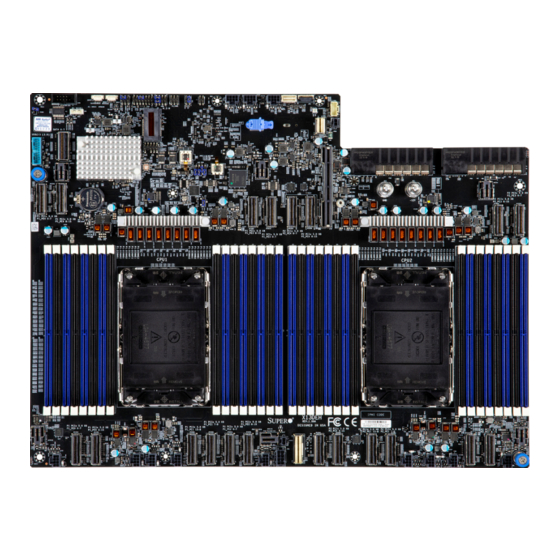
1.1 System Board Overview This chapter provides detailed information on the components installed on the X13DEH system board and specifications/features supported by your computer system. Important Links For your motherboard to work properly, please follow the links below to download all necessary drivers/utilities and the user’s manual for your computer. - Page 8 Super X13DEH User's Manual X13DEH Motherboard Image Note: All graphics shown in this manual were based upon the latest PCB revision available at the time of publication of this manual. The motherboard you received may or may not look exactly the same as the graphics shown in the manual.
- Page 9 Chapter 1: Introduction X13DEH Motherboard Layout (not drawn to scale) JFP1 JPDB1 JFP2 JCOM1 FAN10 FAN11 FAN12 LED2 LED1 JRK1 RAID KEY-1 BIOS M. 2 MH-A M. 2 MH-B LICENSE JPWR3 JUSB3 BIOS Power Supply Unit 1 Power Supply Unit 2...
- Page 10 FAN4 FAN5 Rear Side of the Motherboard Note: Please note that this motherboard has a different orientation from a regular Supermicro motherboard. The front side of this motherboard is facing North, while the rear side of the motherboard, facing South.
- Page 11 Power Supply Unit 1 JTPM1 CPLD Flash JPFR2 PSU2 PSU1 P1_PE4 0-7 CPLD2 Battery PWR_OUT PWR_In JPCIE2B1 JPCIE2A1 JPCIE3A1 JPCIE3B1 P1_PE4 8-15 +12V X13DEH Clear CMOS JBT1 JPCIE1A1 JPCIE1B1 REV:1.01 P1_PE3 8-15 P1_PE3 0-7 JPCIE4A1 JPCIE4B1 CPU1 CPU2 BAR CODE JPCIE5A1 JPCIE5B1...
- Page 12 GND (CST Pin) sideband distributor board located on JPDB1) for use in Nvidia proprietary systems Battery (BT1) Onboard battery Supermicro & Nvidia proprietary I/O board sideband connector CPLD2 Complex Programmable Logic Device (CPLD) header FAN1 - FAN12 8-pin fan headers for system cooling...
- Page 13 VROC RAID Key (JRK1) Intel VROC RAID key header for NVMe RAID support (See Note 2 below.) Note 1: For TPM support, an optional part is needed. Contact Supermicro Technical Support for more information. Note 2: For detailed instructions on how to configure VROC RAID settings, please...
- Page 14 Super X13DEH User's Manual Memory Slots This motherboard supports 3DS RDIMM/RDIMM DDR5 ECC memory with speeds up to 8TB 4800 MT/s in 16 DIMM slots (or up to 4400 MT/s in 32 DIMM slots). Please refer to the layout drawing below for the locations of the DIMM slots:...
- Page 15 Note: Memory speed and capacity support is dependent on the processors used in the system. DIMM Size • Up to 512GB Note: For the latest CPU/memory updates, please refer to our website at http://www.supermicro.com/products/ motherboard. Chipset • Intel PCH C741 Expansion Slots •...
- Page 16 Power Management • Power Supply Unit1/Power Supply Unit2 (PSU1/PSU2) are used to provide main system power to Supermicro (1U) systems • Power Distributor Board (PDB) installed on the power sideband header (JPDB1) is used to supply main power to Nvidia proprietary systems •...
- Page 17 Chapter 1: Introduction X13DEH M2_B CONN M2_A CONN JPCIe2A1, JPCIe2B1 JPCIe3A1, JPCIe3B1 FOR NVMe x8 PORT FOR NVMe x8 PORT JPCIe4A1, JPCIe4B1 JPCIe1A1 JUSB3 PCIe/S-SATA Gen3 PCIe Gen 5 x16 PCIe Gen 5 x16 JPCIe1B1 USB2.0 [12] USB3.1 USB3.0 [2]...
-
Page 18: Processor And Chipset Support
1.2 Processor and Chipset Support Built upon the functionality and capability of the 4th Gen Intel Xeon Scalable Processors (Socket E) and the Intel C741 PCH, the X13DEH motherboard offers critical, pivotal technological breakthroughs that unleash unprecedented computing capabilities and provides a scalable platform optimized for applications used in Artificial Intelligence (AI) Acceleration, Deep Learning Boost, Network Interconnectivity, and Platform Manageability technologies. -
Page 19: Special Features
System Health sensors monitor temperatures and voltage settings of onboard processors and the system in real time via the BMC interface. Whenever the temperature of the CPU or the system exceeds Supermicro’s pre-defined threshold, the system and CPU cooling fan speed will increase to prevent the CPU or system from overheating. -
Page 20: Power Supply
Warning! To avoid damaging the power supply or the motherboard, be sure to connect Power Supply Unit1/Unit2 to your power outlet for use in Supermicro systems, and connect the power sideband distributor board to the +12V CST pin and the GND (Ground) CST pin to provide system power to Nvidia proprietary systems. -
Page 21: Chapter 2 Installation
Chapter 2: Installation Chapter 2 Installation 2.1 Static-Sensitive Devices Electrostatic Discharge (ESD) can damage electronic com ponents. To avoid damaging your motherboard, it is important to handle it very carefully. The following measures are generally sufficient to protect your equipment from ESD. Precautions •... -
Page 22: Processor And Heatsink Installation
Thermal grease is pre-applied on a new heatsink. No additional thermal grease is needed. • Refer to the Supermicro website for updates on processor and memory support. • All graphics in this manual are for illustrations only. Your components may look different. - Page 23 Chapter 2: Installation 1. The 4th Gen Intel Xeon Scalable Processor Processor Top View SP XCC Series Max Series (HBM) SP MCC Series Pin 1 Pin 1 Pin 1 = Cutout = Pin 1 = CPU Key = Cutout = Pin 1 = CPU Key Processor Bottom View...
- Page 24 Super X13DEH User's Manual 2. The Processor Carrier Pin 1 Pin 1 Pin 1 Max Series (HBM) SP MCC Series SP XCC Series Carrier Top View Carrier E1C Carrier E1A Carrier E1B = Cutout = Pin 1 = CPU Key...
- Page 25 Chapter 2: Installation 3. Heatsink 1U Heatsink 2U Heatsink Note: Exercise extreme care when handling the heatsink. Pay attention to the edges of heatsink fins, which can be sharp! To avoid damaging the heatsink, please do not apply excessive force on the fins. Note 2: This installation section provides instructions on how to install 1U heatsink/2U heatsink, which are supported by your system.
-
Page 26: Overview Of The Cpu Socket
Super X13DEH User's Manual Overview of the CPU Socket The CPU socket is protected by a plastic protective cover. Plastic Protective Cover CPU Socket... -
Page 27: Overview Of The Processor Carrier Assembly
Chapter 2: Installation Overview of the Processor Carrier Assembly The processor carrier assembly contains a 4th Gen Intel Xeon Scalable processor and a processor carrier. Carefully follow the instructions given in the installation section to place a processor into the carrier to create a processor carrier. The processor carrier assembly includes a processor and a carrier as shown below: 1. -
Page 28: Overview Of The Processor Heatsink Module (Phm)
Super X13DEH User's Manual Overview of the Processor Heatsink Module (PHM) The Processor Heatsink Module (PHM) contains a heatsink, a processor carrier, and a 4th Gen Intel Xeon Scalable processor. 1. Heatsink: For SP XCC CPU Illustration (Bottom View Shown Below) - Page 29 Chapter 2: Installation 1. Heatsink: For Max Series (HBM) CPU Illustration (Bottom View Shown Below) 2U Heatsink 1U Heatsink 2. Processor Carrier E1C 3. The 4th Gen Intel Xeon Scalable Processor (Max Series ((HBM)) Component Side) 4. Processor Heatsink Module (PHM) (Bottom View Shown Below) 2U Heatsink 1U Heatsink...
- Page 30 Super X13DEH User's Manual 1. Heatsink: For SP MCC CPU Illustration (Bottom View Shown Below) 1U Heatsink 2U Heatsink 2. CPU Carrier E1B 3. The 4th Gen Intel Xeon Scalable Processor (SP MCC) (Component Side) 4. Processor Heatsink Module (PHM) (Bottom View Shown Below)
-
Page 31: Creating The Processor Carrier Assembly
Chapter 2: Installation Creating the Processor Carrier Assembly The processor carrier assembly contains a 4th Gen Intel Xeon Scalable processor and a processor carrier. To create the processor carrier assembly, please follow the steps below: Note: Before installation, be sure to follow the instructions given on pages 1 and 2 of this chapter to properly prepare for installation. - Page 32 Super X13DEH User's Manual 2. First, turn over the processor carrier and locate Pin 1 on the CPU and Pin 1 on the carrier. Then, turn the processor over with component side (including the gold contacts) facing up and locate CPU keys on the processor. Finally, locate the CPU keys and four latches on the carrier as shown below.
- Page 33 Chapter 2: Installation 3. Locate the lever on the CPU socket and press it down as shown below. Lever Lever Carrier E1A Carrier E1B 4. Using Pin 1 as a guide, carefully align the CPU keys (A and B) on the processor against the CPU keys on the carrier (a and b) as shown in the drawing below.
- Page 34 Super X13DEH User's Manual 6. After the processor is placed inside the carrier, examine the four sides of the processor, making sure that the processor is properly seated on the carrier. CPU Carrier Assembly (Top View) (Component View) SP XCC...
-
Page 35: Creating The Phm
Chapter 2: Installation Creating the PHM After creating the processor carrier assembly, please follow the instructions below to mount the processor carrier into the heatsink to form the PHM. Note: If this is a new heatsink, the thermal grease has been pre-applied on the un- derside. - Page 36 Super X13DEH User's Manual CPU Carrier Assembly (CPU Component Side & Heatsink Bottom Side) Max Series (HBM) SP XCC Pin 1 Pin 1 SP MCC Pin 1 Processor Heatsink Module (PHM) 1U Heatsink...
- Page 37 Chapter 2: Installation SP XCC Max Series (HBM) Pin 1 Pin 1 SP MCC Pin 1 Processor Heatsink Module (PHM) 2U Heatsink...
-
Page 38: Preparing The Cpu Socket For Installation
Super X13DEH User's Manual Preparing the CPU Socket for Installation This motherboard comes with a plastic protective cover installed on the CPU socket. Remove it from the socket by following the instructions below: 1. Press the tabs inward. 2. Pull up the protective cover from the socket. -
Page 39: Preparing To Install The Phm Into The Cpu Socket
Chapter 2: Installation Preparing to Install the PHM into the CPU Socket After assembling the Processor Heatsink Module, you are ready to install it into the CPU socket. To ensure the proper installation, please follow the procedures below: 1. Locate four threaded fasteners (a, b, c, d) on the CPU socket. CPU Socket (a, b, c, d: Threaded Fasteners) CPU Socket Pin1... - Page 40 Super X13DEH User's Manual 2. Locate four PEEK nuts (A, B, C, D) and four rotating wires (1, 2, 3, 4) on the heatsink as shown in the graphics below. A, B, C, D: PEEK Nut Heatsink (Reverse Side) Rotating Wire...
- Page 41 Chapter 2: Installation 3. Check the rotating wires (1, 2, 3, 4) to make sure that they are at the unlatched positions as shown in the drawing below before installing the PHM into the CPU socket. Unlatched State Top View Side View Rotating Wire 1 PEEK Nut...
-
Page 42: Installing The Phm Into The Cpu Socket
Super X13DEH User's Manual Installing the PHM into the CPU Socket 1. Align PEEK nut A, which is next to the triangle (Pin 1) on the heatsink, against threaded fastener a on the CPU socket. Then align PEEK nuts B, C, and D on the heatsink... - Page 43 Chapter 2: Installation 3. Press all four rotating wires outwards and make sure that the heatsink is securely latched onto the CPU socket. Latched State 1U Heatsink Latched State 2U Heatsink...
- Page 44 Super X13DEH User's Manual 4. With a T30 screwdriver, tighten all PEEK nuts in the sequence of A, B, C, and D with even pressure. To avoid damaging the processor or socket, do not use excessive force when tightening the PEEK nuts. (For best durability, 8in-lbf torque is recommended.) 5.
-
Page 45: Removing The Phm From The Cpu Socket
Chapter 2: Installation Removing the PHM from the CPU Socket Before removing the PHM from the motherboard, be sure to shut down the system and unplug the power cables from the power supply. Then follow the steps below: 1. Use a T30 screwdriver to loosen the four PEEK nuts on the heatsink in the sequence of A, B, C, and D. - Page 46 Super X13DEH User's Manual 2. Once the PEEK nuts are loosened from the CPU socket, press the rotating wires inwards to unlatch the PHM from the socket as shown in the drawings below. Unlatched State 1U Heatsink Unlatched State 2U Heatsink...
- Page 47 Chapter 2: Installation 3. Gently pull the PHM upwards to remove it from the CPU socket. 1U Heatsink 2U Heatsink...
-
Page 48: Removing The Processor Carrier Assembly From The Phm
Super X13DEH User's Manual Removing the Processor Carrier Assembly from the PHM To remove the processor carrier assembly from the PHM, please follow the steps below: 1. Detach the four plastic clips (marked a, b, c, d) on the processor carrier assembly from the four corners of the heatsink (marked A, B, C, D) as shown in the drawings below. - Page 49 Chapter 2: Installation 2. When all plastic clips are detached from the heatsink, remove the processor carrier assembly from the heatsink. 1U Heatsink (View of Component Side & Heatsink Bottom Side) SP XCC Max Series (HBM) SP MCC 2U Heatsink (View of Component Side & Heatsink Bottom Side) SP MCC Max Series (HBM) SP XCC...
-
Page 50: Removing The Processor From The Processor Carrier Assembly
Super X13DEH User's Manual Removing the Processor from the Processor Carrier Assembly Once you have removed the processor carrier assembly from the PHM, you are ready to remove the processor from the processor carrier by following the steps below. 1. Unlock the lever from its locked position and push the lever upwards to disengage the processor from the processor carrier as shown in the drawing on the right below. -
Page 51: Motherboard Installation
Power Supply Unit 1 Power Supply Unit 2 JTPM1 CPLD Flash JPFR2 PSU2 PSU1 CPLD2 Battery PWR_OUT PWR_In JPCIE2B1 JPCIE2A1 JPCIE3A1 JPCIE3B1 +12V X13DEH JBT1 REV:1.01 JPCIE1A1 JPCIE1B1 JPCIE4A1 JPCIE4B1 CPU1 CPU2 BAR CODE JNCSI1 JPCIE5A1 JPCIE5B1 JPCIE6B1 JPCIE6A1 JPCIE7A1... - Page 52 Super X13DEH User's Manual Installing the Motherboard 1. Install the I/O shield into the back of the chassis, if applicable. 2. Locate the mounting holes on the motherboard. See the previous page for the location. 3. Locate the matching mounting holes on the chassis. Align the mounting holes on the motherboard against the mounting holes on the chassis.
-
Page 53: Memory Support And Installation
Chapter 2: Installation 2.4 Memory Support and Installation Note: Check the Supermicro website for recommended memory modules. Important: Exercise extreme care when installing or removing memory modules to prevent any possible damage. Memory Support This motherboard supports up to 8TB RDIMM DDR5 (288-pin) ECC memory with speeds up to 4800MT/s in 16 DIMM slots and 4400MT/s in 32 DIMM slots. - Page 54 2 CPUs & 24 DIMMs DIMME1/P1-DIMME2/P1-DIMMF1/P1-DIMMF2/P1-DIMMG1/P1-DIMMG2/P1-DIMMH1/P1-DIMMH2 CPU2: P2-DIMMA1/P2-DIMMB1/P2-DIMMC1/P2-DIMMD1/P2-DIMME1/P2-DIMMF1/P2-DIMMG1/P2-DIMMH1 CPU1: P1-DIMMA1/P1-DIMMA2/P1-DIMMB1/P1-DIMMB2/P1-DIMMC1/P1-DIMMC2/P1-DIMMD1/P1-DIMMD2/P1- DIMME1/P1-DIMME2/P1-DIMMF1/P1-DIMMF2/P1-DIMMG1/P1-DIMMG2/P1-DIMMH1/P1-DIMMH2 2 CPUs & 32 DIMMs CPU2: P2-DIMMA1/P2-DIMMA2/P2-DIMMB1/P2-DIMMB2/P2-DIMMC1/P2-DIMMC2/P2-DIMMD1/P2-DIMMD2/P2- DIMME1/P2-DIMME2/P2-DIMMF1/P2-DIMMF2/P2-DIMMG1/P2-DIMMG2/P2-DIMMH1/P2-DIMMH2 Note: This memory configuration is recommended by Supermicro for optimal memory performance. Please use this configuration to maximize your memory performance.
- Page 55 Chapter 2: Installation DDR5 Memory Population Table (with Max Series ((HBM)) CPUs and 32 DIMMs Installed) 1 CPU: Memory Population Sequence P1-DIMMA1 1 CPU & 1 DIMM P1-DIMME1 P1-DIMMA1/P1-DIMMG1 1 CPU & 2 DIMMs P1-DIMMC1/P1-DIMME1 1 CPU & 4 DIMMs P1-DIMMA1/P1-DIMMC1/P1-DIMME1/P1-DIMMG1 1 CPU &...
- Page 56 Super X13DEH User's Manual DIMM Installation JFP1 JPDB1 JFP2 JCOM1 FAN10 FAN11 FAN12 LED2 LED1 JRK1 RAID KEY-1 BIOS LICENSE M. 2 MH-A M. 2 MH-B JPWR3 JUSB3 BIOS 1. Insert the desired number of DIMMs into the memory Power Supply Unit 2...
-
Page 57: Front Control Panel Headers
Two front control panel headers (JFP1/JFP2) are located on front side of the motherboard. Front Control Panel Header 1 (JFP1) is a Supermicro proprietary control panel header that contains header pins for various buttons and LED indications with I²C support for front access. - Page 58 Super X13DEH User's Manual Power On The Power On and BMC/BIOS Status LED button is located on Pin 1 of the front control panel header (JFP1). Momentarily contacting Pin 1 of JFP1 will power on/off the system. Refer to the table below for more information.
- Page 59 Power Supply Unit 1 JTPM1 CPLD Flash 3. Pin 4: Fail LED JPFR2 PSU2 PSU1 CPLD2 Battery PWR_OUT PWR_In JPCIE2B1 JPCIE2A1 JPCIE3A1 JPCIE3B1 +12V X13DEH JBT1 JPCIE1A1 JPCIE1B1 REV:1.01 JPCIE4A1 JPCIE4B1 CPU1 CPU2 BAR CODE JNCSI1 JPCIE5A1 JPCIE5B1 JPCIE6B1 JPCIE6A1 JPCIE7A1...
- Page 60 Super X13DEH User's Manual LAN1 LED/LAN2 LED The Network Interface LED connection for LAN Port 1 is located on Pin 6 of JFP1, and LAN Port 2 is on Pin 5. Refer to the tables below. LAN1/LAN2 LED LED States...
- Page 61 Power Supply Unit 1 JTPM1 CPLD Flash 3. Pin 9: RoT PWR On (Negative) JPFR2 PSU2 PSU1 CPLD2 Battery PWR_OUT PWR_In JPCIE2B1 JPCIE2A1 JPCIE3A1 JPCIE3B1 +12V X13DEH JBT1 JPCIE1A1 JPCIE1B1 REV:1.01 JPCIE4B1 JPCIE4A1 CPU1 CPU2 BAR CODE JPCIE5A1 JPCIE5B1 JPCIE6B1 JPCIE6A1 JPCIE7A1 JPCIE7B1...
- Page 62 Super X13DEH User's Manual Standby Power SMB (I²C) A Standby Power (I C) connection, located on Pin 10 ~ Pin 14 of JFP1, provides power to the system when it is in standby mode. Refer to the table below for Pin definitions.
- Page 63 Power Supply Unit 2 Power Supply Unit 1 JTPM1 CPLD Flash JPFR2 PSU2 PSU1 CPLD2 Battery PWR_OUT PWR_In JPCIE2B1 JPCIE2A1 JPCIE3A1 JPCIE3B1 +12V X13DEH JBT1 JPCIE1A1 JPCIE1B1 REV:1.01 JPCIE4B1 JPCIE4A1 CPU1 CPU2 BAR CODE JPCIE5A1 JPCIE5B1 JPCIE6B1 JPCIE6A1 JPCIE7A1 JPCIE7B1...
- Page 64 I/O support for user interaction and application. It is an Nvidia proprietary connector, and the information pertaining to this header is used under a partnership agreement between Supermicro and Nvidia. See the layout below for the location of JFP2. 1. JFP2: Nvidia Proprietary control panel...
-
Page 65: Connectors And Headers
Important: To provide adequate power to your system, be sure to connect Power Supply Unit1/Unit2 to your power outlet to provide adequate power to Supermicro (1U) systems. Connect the power sideband distributor board to the +12V CST pin and the GND (Ground) CST pin to provide power to Nvidia proprietary systems. - Page 66 The JTPM1 header is used to support the Trusted Platform Module (TPM)/Port 80, which is available from Supermicro (optional). The TPM/Port 80 module is a security device that supports encryption and authentication in hard drives. It allows the motherboard to deny access to the system if the TPM key associated with the hard drive is not installed in the system.
- Page 67 Power Supply Unit 2 JTPM1 CPLD Flash 2. FAN2 JPFR2 PSU2 PSU1 3. FAN3 CPLD2 Battery PWR_OUT PWR_In JPCIE2B1 JPCIE2A1 JPCIE3A1 JPCIE3B1 +12V X13DEH 4. FAN4 JBT1 JPCIE1A1 JPCIE1B1 REV:1.01 JPCIE4A1 JPCIE4B1 5. FAN5 6. FAN6 7. FAN7 CPU1 8. FAN8 CPU2 9.
- Page 68 Super X13DEH User's Manual Chassis Intrusion A Chassis Intrusion header is located at JL1 on the front side of the motherboard. Attach the appropriate cable from the chassis to this header to inform you of possible chassis intrusion when the chassis is opened. Refer to the table below for pin definitions.
- Page 69 Power Supply Unit 1 JTPM1 CPLD Flash Bus Connector JPFR2 PSU2 PSU1 CPLD2 Battery PWR_OUT PWR_In JPCIE2B1 JPCIE2A1 JPCIE3A1 JPCIE3B1 +12V X13DEH JBT1 REV:1.01 JPCIE1A1 JPCIE1B1 JPCIE4B1 JPCIE4A1 CPU1 CPU2 BAR CODE JNCSI1 JPCIE8A1 JPCIE8B1 JPCIE5A1 JPCIE5B1 JPCIE6B1 JPCIE6A1 JPCIE7A1...
- Page 70 Super X13DEH User's Manual VROC RAID Key Header A VROC RAID Key header is located at JRK1 on the motherboard. Install a VROC RAID key on JRK1 for VROC (Virtual RAID on CPU) RAID support as shown in the illustration below.
- Page 71 JTPM1 CPLD Flash "A" for M-Key 2280 JPFR2 PSU2 PSU1 support CPLD2 Battery PWR_OUT PWR_In JPCIE2B1 JPCIE2A1 JPCIE3A1 JPCIE3B1 +12V X13DEH JBT1 3. M.2 Mounting Hole REV:1.01 JPCIE1A1 JPCIE1B1 JPCIE4B1 JPCIE4A1 "B" for M-Key 22110 support CPU1 CPU2 BAR CODE...
- Page 72 Super X13DEH User's Manual COM Port Pin Table Header for Debugging A COM (communication) port pin table header used for debugging is located at JCOM1 on the front side of the motherboard. Refer to the board layout below for the location of JCOM1.
- Page 73 Power Supply Unit 1 Power Supply Unit 2 JTPM1 CPLD Flash JPFR2 PSU2 PSU1 CPLD2 Battery PWR_OUT PWR_In JPCIE2B1 JPCIE2A1 JPCIE3A1 JPCIE3B1 +12V X13DEH JBT1 JPCIE1A1 JPCIE1B1 REV:1.01 JPCIE4A1 JPCIE4B1 CPU1 CPU2 BAR CODE JPCIE5A1 JPCIE5B1 JPCIE6B1 JPCIE6A1 JPCIE7A1 JPCIE7B1...
- Page 74 Super X13DEH User's Manual PCIe 5.0 x8 via MCIO Vertical Connectors This motherboard supports 20 PCIe 5.0 x8 via MCIO Vertical connectors that can be used for PCIe high-speed storage devices. These connectors are supported by CPU 1 or CPU2.
- Page 75 Power Supply Unit 2 Power Supply Unit 1 JTPM1 CPLD Flash JPFR2 PSU2 PSU1 CPLD2 Battery PWR_OUT PWR_In JPCIE2B1 JPCIE2A1 JPCIE3A1 JPCIE3B1 +12V X13DEH JBT1 REV:1.01 JPCIE1A1 JPCIE1B1 JPCIE4B1 JPCIE4A1 CPU1 CPU2 BAR CODE JNCSI1 JPCIE8A1 JPCIE8B1 JPCIE5A1 JPCIE5B1 JPCIE6B1 JPCIE6A1 JPCIE7A1...
- Page 76 Super X13DEH User's Manual I/O Board Sideband Connector (CN4) A Supermicro & Nvidia proprietary I/O board sideband connector, located at CN4 on the rear side of the motherboard, provides AIOM sideband support. See the layout below for the location of CN4.
-
Page 77: Jumper Settings
Chapter 2: Installation 2.7 Jumper Settings Connector Pins How Jumpers Work Jumper To modify the operation of the motherboard, jumpers can be used to choose between optional settings. Jumpers Setting create shorts between two pins to change the function of the connector. - Page 78 Super X13DEH User's Manual CMOS Clear JBT1 is used to clear CMOS, which will also clear any passwords. Instead of pins, this jumper consists of contact pads to prevent accidentally clearing the contents of CMOS. To Clear CMOS 1. First power down the system and unplug the power cord(s).
- Page 79 Power Supply Unit 1 Power Supply Unit 2 JTPM1 CPLD Flash JPFR2 PSU2 PSU1 CPLD2 Battery PWR_OUT PWR_In JPCIE2B1 JPCIE2A1 JPCIE3A1 JPCIE3B1 +12V X13DEH JBT1 JPCIE1A1 JPCIE1B1 REV:1.01 JPCIE4A1 JPCIE4B1 CPU1 CPU2 BAR CODE JPCIE5A1 JPCIE5B1 JPCIE6B1 JPCIE6A1 JPCIE7A1 JNCSI1...
- Page 80 Super X13DEH User's Manual Platform Firmware Resilience Jumper (JPFR2) Jumper JPFR2 is used to enhance and synchronize system firmware features for overall platform performance optimization. The JPFR2 connector contains the Firmware Optimization chip that will allow the user to customize platform firmware settings by configuring the pins contained in the JPFR2 chip.
-
Page 81: Led Indicators
Power Supply Unit 1 Power Supply Unit 2 JTPM1 CPLD Flash JPFR2 PSU2 PSU1 CPLD2 PWR_OUT PWR_In Battery JPCIE2B1 JPCIE2A1 JPCIE3A1 JPCIE3B1 +12V X13DEH JBT1 JPCIE1A1 JPCIE1B1 REV:1.01 JPCIE4A1 JPCIE4B1 CPU1 CPU2 BAR CODE JNCSI1 JPCIE8A1 JPCIE8B1 JPCIE5A1 JPCIE5B1 JPCIE6B1 JPCIE6A1 JPCIE7A1... - Page 82 Super X13DEH User's Manual Unit ID LED The front UID LED indicator is located at LED1. This UID indicator provides easy identification of a system that may need be in need of attention or service. UID LED (LED1) LED Indicator...
-
Page 83: Chapter 3 Troubleshooting
Chapter 3: Troubleshooting Chapter 3 Troubleshooting 3.1 Troubleshooting Procedures Use the following procedures to troubleshoot your system. If you have followed all of the procedures below and still need assistance, refer to the ‘Technical Support Procedures’ and/ or ‘Returning Merchandise for Service’ section(s) in this chapter. Always disconnect the AC power cord before adding, changing, or installing any non hot-swap hardware components. - Page 84 Super X13DEH User's Manual System Boot Failure If the system does not display POST (Power-On-Self-Test) or does not respond after the power is turned on, check the following: 1. Remove all components from the motherboard, especially the DIMM modules. Power on the system and check if the Power Status LED (LED2) is on, and system fans are spinning.
- Page 85 Chapter 3: Troubleshooting 2. Memory support: Make sure that the memory modules are supported by testing the modules using memtest86 or a similar utility. Note: Click on the "Tested Memory List" link on the motherboard's product page to see a list of supported memory. 3.
-
Page 86: Technical Support Procedures
Before contacting Technical Support, please take the following steps. Also, please note that as a motherboard manufacturer, Supermicro also sells motherboards through its channels, so it is best to first check with your distributor or reseller for troubleshooting services. They should know of any possible problems with the specific system configuration that was sold to you. -
Page 87: Frequently Asked Questions
BIOS revision to make sure that it is newer than your BIOS before downloading. Note 1: The SPI BIOS chip used on this motherboard cannot be removed. Send your motherboard back to our RMA Department at Supermicro for repair. Note 2: For BIOS Update and Recovery instructions, please refer to the Firmware Update and Recovery Instructions for Supermicro's X13 Motherboards User's Guide posted at http://www.supermicro.com/support/manuals/. -
Page 88: Battery Removal And Installation
Super X13DEH User's Manual 3.4 Battery Removal and Installation Battery Removal To remove the onboard battery, follow the steps below: 1. Power off your system and unplug your power cable. 2. Locate the onboard battery as shown below. 3. Using a tool such as a pen or a small screwdriver, push the battery lock outwards to unlock it. -
Page 89: Returning Merchandise For Service
For faster service, you can also request a RMA authorization online (http://www.supermicro. com/RmaForm/). The manufacturer warranty only covers normal consumer use and does not cover damages incurred in shipping or from failure caused by alternation, misuse, abuse or improper maintenance of products. -
Page 90: Chapter 4 Uefi Bios
Super X13DEH User's Manual Chapter 4 UEFI BIOS 4.1 Introduction This chapter describes the AMIBIOS™ Setup utility for the motherboard. The BIOS is stored on a chip and can be easily upgraded using the BMC WebUI or the SUM utility. -
Page 91: Main Setup
Note: The time is in the 24-hour format. For example, 5:30 P.M. appears as 17:30:00. The date's default value is the BIOS build date after the RTC (Real Time Clock) reset. Supermicro X13DEH BIOS Version This feature displays the version of the BIOS ROM used in the system. - Page 92 Super X13DEH User's Manual Memory Information Total Memory This feature displays the total size of memory available in the system.
-
Page 93: Advanced Setup Configurations
Chapter 4: UEFI BIOS 4.3 Advanced Setup Configurations Use the arrow keys to select the Advanced submenu and press <Enter> to access the submenu items: Warning: Take caution when changing the Advanced settings. An incorrect value, an improper DRAM frequency, or a wrong BIOS timing setting may cause the system to malfunction. When this occurs, restore the setting to the manufacturer default setting. - Page 94 MS-SINGLE) is Supermicro’s Data Center Management Suite license that enables server node to take full advantage of Supermicro Management Software and Utilities features. Contact us for more information. Note 2: Refer to the submenu of Security > Supermicro Security Erase Configuration to set "Lockdown Mode".
- Page 95 Chapter 4: UEFI BIOS Rear USB Port(s) (Available when "Lockdown Mode" is set to Enabled with the DCMS key) Select Enabled to allow the specific type of USB devices to be used in the rear USB ports. Select Enabled (Dynamic) to allow or disallow this particular type of USB devices to be used in the rear USB ports without rebooting the system.
- Page 96 Super X13DEH User's Manual • Processor 0 Version • Processor 1 Version Advanced Power Management Configuration Power Technology Select Energy Efficient to support power-saving mode. Select Custom to customize system power settings. Select Disabled to disable power-saving settings. The options are Disable, Energy Efficient, and Custom.
- Page 97 Chapter 4: UEFI BIOS CPU P State Control This feature allows you to configure the following CPU power settings: AVX P1 (Available when "SpeedStep (P-States)" is set to Enable) Use this feature to set the appropriate TDP level for the system. The Intel Advanced Vector Extensions (Intel AVX) P1 feature allows you to set the base P1 ratio for Streaming SIMD Extensions (SSE) and AVX workloads.
- Page 98 Super X13DEH User's Manual EIST PSD Function (Available when "SpeedStep (P-States)" is set to Enable) This feature reduces the latency that occurs when one P-state changes to another, thus allowing the transitions to oc- cur more frequently. This will allow for more demand-based P-state switching to occur based on the real-time energy needs of applications so that the power-to-performance balance can be optimized for energy efficiency.
- Page 99 Chapter 4: UEFI BIOS CPU C6 Report Select Enable to allow the BIOS to report the CPU C6 State (ACPI C3) to the operating system. During the CPU C6 State, the power to all cache is turned off. The options are Disable, Enable, and Auto. (ACPI is the abbreviation for Advanced Configuration and Power Interface.) Enhanced Halt State (C1E) Select Enable to enable "Enhanced Halt State"...
- Page 100 Super X13DEH User's Manual DCU IP Prefetcher This feature allows the system to use the sequential load history, which is based on the instruction pointer of previous loads, to determine whether the system will prefetch additional lines. The options are Enable and Disable.
- Page 101 Chapter 4: UEFI BIOS ---------------------------------------------------------------- TME, TME-MT, TDX ---------------------------------------------------------------- Memory Encryption (TME) (Available when your CPU supports Intel TME) Select Enabled for Intel Total Memory Encryption (TME) support to enhance memory data security. The options are Disabled and Enabled. Total Memory Encryption (TME) Bypass (Available when "Memory Encryption (TME)" is set to Enabled) Use this feature to disable/enable the TME function for physical memory protection.
- Page 102 Super X13DEH User's Manual ---------------------------------------------------------------- Software Guard Extension (SGX) ---------------------------------------------------------------- *The following SGX features are available when "Memory Encryption (TME)" is set to Enabled and when your CPU supports Intel SGX. Note: Each memory channel must have at least one DIMM populated on the mother- board to support the Intel SGX features.
- Page 103 Chapter 4: UEFI BIOS Software Guard Extensions Epoch 0 (Available when "SW Guard Extensions (SGX)" is set to Enabled and "Select Owner EPOCH input type" is set to Manual User Defined Owner EPOCHs) Use this feature to enter the EPOCH value. The default is 0. Software Guard Extensions Epoch 1 (Available when "SW Guard Extensions (SGX)"...
- Page 104 Super X13DEH User's Manual Chipset Configuration Warning: Setting the wrong values in the following features may cause the system to malfunc- tion. North Bridge This feature allows you to configure the following North Bridge settings. Uncore Configuration The following information is displayed.
- Page 105 Chapter 4: UEFI BIOS KTI Prefetch Keizer Technology Interconnect (KTI) is also known as the Intel Ultra Path Interconnect (UPI) technology. Select Enable for the KTI prefetcher to preload the L1 cache with data deemed relevant, which will allow the memory read to start earlier on a DDR bus in an effort to reduce latency.
- Page 106 Super X13DEH User's Manual Data Scrambling for PMem (Available when any PMem device is detected by the BIOS) Select Enable to enable data scrambling for PMem modules to enhance memory data security. Select Auto to use the Memory Reference Code (MRC) defaulting setting for PMem data scrambling. The options are Disable, Enable, and Auto.
- Page 107 Chapter 4: UEFI BIOS Flush Timeout Value (Available when "Flush Timeout" is set to Manual) Use this feature to enter the flush timeout value. The default value is FFF. DDR 2X Refresh Enable Select Enable for memory 2X refresh support to enhance memory performance. The options are Auto, Disable, and Enable. CXL Type 3 Legacy Select Enable to use the CXL Type 3 memory device, which can be supported by the CXL Type 2 flows, for memory bandwidth and capacity expansion.
- Page 108 Super X13DEH User's Manual Leaky Bucket Low Bit Use this feature to set the Low Bit value for the Leaky Bucket algorithm which is used to check the data transmissions between CPU sockets and the memory controller. The default setting is 11.
- Page 109 Chapter 4: UEFI BIOS IIO Configuration CPU1 Configuration / CPU2 Configuration IOU0 (IIO PCIe Port 1) This feature is CPU-dependent. Use this feature to configure the PCIe Bifurcation setting for a PCIe port specified by the user. The options are Auto, x4x4x4x4, x4x4x8, x8x4x4, x8x8, and x16. IOU1 (IIO PCIe Port 2) This feature is CPU-dependent.
- Page 110 Super X13DEH User's Manual Data Link Feature Exchange Use this feature to enable/disable the PCIe port to enter PCIe 4.0 DL_Feature ne- gotiation state. The options are Disable and Enable. PCIe Port Max Payload Size Use this feature to set the maximum payload size supported in Direct Media Inter- face (DMI) device capabilities register for the device installed in the PCIe port.
- Page 111 Chapter 4: UEFI BIOS Intel VMD Technology This section describes the configuration settings for the Intel VMD technology. Note 1: After you’ve enabled VMD in the BIOS on a PCIe slot, this PCIe slot will be dedicated for VMD use only, and it will no longer support any PCIe device. To re-activate this slot for PCIe use, please disable VMD in the BIOS.
- Page 112 Super X13DEH User's Manual VMD Config for IOU 4 / VMD Config for IOU 5 / VMD Config for IOU 6 (Available when the device is detected by the BIOS) Enable/Disable VMD Select Enable to enable the Intel VMD technology support for the root port specified.
- Page 113 Chapter 4: UEFI BIOS PCIe Leaky Bucket Configuration Gen2 Link Degradation Use this feature to enable PCIe Gen. 2 link degradation. The options are Disable and Enable. Gen3 Link Degradation Use this feature to enable PCIe Gen. 3 link degradation. The options are Disable and Enable. Gen4 Link Degradation Use this feature to enable PCIe Gen.
- Page 114 Super X13DEH User's Manual CXL Security Level By defining security protocols, CXL standards provide protection against the data security threats. Use this feature to set the CXL security level for data transiting the CXL link. The options are Fully Trusted, Partially Trusted, Untrusted, and Auto.
- Page 115 Chapter 4: UEFI BIOS Server ME Information The following information is displayed: • General ME Configuration • Oper. Firmware Version • Current State • Error Code PCH SATA0 Configuration / PCH SATA1 Configuration / SATA2 Configuration When this submenu is selected, the AMI BIOS automatically detects the presence of a SATA device supported by the Intel PCH chip and displays the following features.
- Page 116 Super X13DEH User's Manual Hot Plug Select Enabled to support Hot-plugging for the device installed on a selected SATA port to allow you to replace the device installed in the slot without shutting down the system. The options are Disabled and Enabled.
- Page 117 Chapter 4: UEFI BIOS SHA256 PCR Bank (Available when "Security Device Support" is set to Enable) Select Enabled to enable SHA256 PCR Bank support to enhance system integrity and data security. The options are Disabled and Enabled. Pending Operation (Available when "Security Device Support" is set to Enable) Use this feature to schedule a TPM-related operation to be performed by a security (TPM) device at the next system boot to enhance system data integrity.
- Page 118 Disabled and Enabled. Supermicro BIOS-Based TPM Provision Support If this feature is set to Enabled, Supermicro BIOS-based TPM provision will be supported. The options are Disabled and Enabled. Note: Enabling this feature will lock your TPM on the production platform, and you will not be able to delete the NV indexes.
- Page 119 Chapter 4: UEFI BIOS Super IO Configuration (Available when your system supports this feature) The following information is displayed. • Super IO Chip Serial Port 1 Configuration Serial Port 1 Select Enabled to enable serial port 1. The options are Disabled and Enabled. Device Settings (Available when "Serial Port 1"...
- Page 120 Super X13DEH User's Manual Serial Port Console Redirection COM1 (Available when your system supports the serial port of COM1) Console Redirection Select Enabled to enable COM port 1 for Console Redirection, which allows a client machine to be connected to a host machine at a remote site for networking. The options are Disabled and Enabled.
- Page 121 Chapter 4: UEFI BIOS Flow Control Use this feature to set the flow control for Console Redirection to prevent data loss caused by buffer overflow. Send a "Stop" signal to stop sending data when the receiving buffer is full. Send a "Start" signal to start sending data when the receiving buffer is empty. The options are None and Hardware RTS/CTS.
- Page 122 Super X13DEH User's Manual Bits Per Second Use this feature to set the transmission speed for a serial port used in Console Redirection. Make sure that the same speed is used in the host computer and the client computer. A lower transmission speed may be required for long and busy lines.
- Page 123 Chapter 4: UEFI BIOS Legacy Console Redirection Legacy Console Redirection Settings Legacy Serial Redirection Port Use this feature to select a COM port to display redirection of Legacy OS and Legacy OPROM messages. The options are COM1 and SOL/COM2. Please note that the available options are based on your motherboard features.
- Page 124 Super X13DEH User's Manual Bits Per Second EMS This feature sets the transmission speed for a serial port used in Console Redirection. Make sure that the same speed is used in the host computer and the client computer. A lower transmission speed may be required for long and busy lines. The options are 9600, 19200, 57600, and 115200 (bits per second).
- Page 125 Chapter 4: UEFI BIOS Media Detect Count Use this feature to select the wait time (in seconds) for the BIOS ROM to detect the presence of a LAN media either via the Internet connection or via a LAN port. Press "+" or "-" on your keyboard to change the value.
- Page 126 Super X13DEH User's Manual Save Changes and Exit Press <Enter> to save changes and exit. The options are Yes and No. MAC:(MAC address)-IPv4 Network Configuration Configured Select Enabled to show whether the network address has been successfully configured. The options are Enabled and Disabled.
- Page 127 Chapter 4: UEFI BIOS PCIe/PCI/PnP Configuration The following information is displayed: • PCI Bus Driver Version PCI Devices Common Settings: Above 4G Decoding (Available when the system supports 64-bit PCI decoding) Select Enabled to decode a PCI device that supports 64-bit in the space above 4G Address. The options are Disabled and Enabled.
- Page 128 Super X13DEH User's Manual Bus Master Enable If it is set to Enabled, the PCI Bus Driver will enable the Bus Master Attribute for DMA transactions. If it is set to Disabled, the PCI Bus Driver will disable the Bus Master Attribute for Pre-Boot DMA protection.
- Page 129 Chapter 4: UEFI BIOS Onboard LAN1 Option ROM (Available when "Onboard LAN Device" is set to Enabled) Use this feature to select the type of device installed in LAN Port 1 used for system boot. The options are Disabled, PXE, iSCSI, Legacy, FCoE, and EFI. Please note that available options are based on your LAN OPROM ROM.
- Page 130 Supermicro KMS TCP Port number Use this feature to set the TCP port number used in Supermicro KMS Server. The valid range is 100–9999. The default setting is 5696. Do not change the default setting unless a different TCP port number has been specified and used in the Supermicro KMS Server.
- Page 131 Note 1: Be sure that the KMS Server is ready before configuring this feature. Note 2: Use the professional KMS Server solutions (e.g., Thales Server) or the Supermicro PyKMIP Software Package to establish the KMS Server. KMS Server Retry Count (Available when "TPM Security Policy" and "USB Security Policy"...
- Page 132 Super X13DEH User's Manual TPM Security Policy (Available when "KMS Security Policy" and "USB Security Policy" are set to Disabled) Select Enabled to support the TPM Security Policy. The options are Disabled and Enabled. Save settings (you can press <F4>) and reboot the system for changes to take effect.
- Page 133 Chapter 4: UEFI BIOS Firmware Image Properties (Available when related devices are detected by the BIOS) The following information is displayed: • Family Firmware Version • EFI Version NIC Configuration Banner Message Time Out Use this feature to specify how long the OptionROM banner message should be displayed during POST (Power On Self-Testing).
- Page 134 Super X13DEH User's Manual Boot Legacy Interrupt Disable Select Enabled to disable the feature support for "Boot Legacy Interrupt Disable". The options are Enabled and Disabled. DHCP HW Type IB When this feature is set to Enabled, DHCP networking signals will be sent with GUID in IB mode.
- Page 135 Chapter 4: UEFI BIOS • Default Gateway • Primary DNS (Domain Network System) iSCSI Name • CHAP ID • CHAP Secret • IPv6 Address • IPv6 Default Gateway • IPv6 Primary DNS (Domain Network System) • IPv6 Prefix Length iSCSI First Target Parameters This feature displays the following information on the iSCSI First Target Parameters.
- Page 136 Super X13DEH User's Manual Virtualization Mode This feature allows the user to specify the type of Virtualization to be used by the Networking controller to communicate with all related ports for networking. The options are None and SR-IOV. PCI Virtual Functions Advertised Use this feature to specify the number of virtual functions supported by the device selected by the user.
- Page 137 Chapter 4: UEFI BIOS • MAC Address • Virtual MAC Address Socket Direct Operation This feature indicates whether Socket Direct Functionality is enabled. The default setting is Disabled. TLS Authenticate Configuration This submenu allows you to configure Transport Layer Security (TLS) settings. Server CA Configuration This feature allows you to configure the client certificate that is to be used by the server.
- Page 138 Super X13DEH User's Manual Enroll Certification Using File This feature allows you to enroll the security certificate in the system by using a file. Certification GUID Press <Enter> and input the certification GUID. Commit Changes and Exit Use this feature to save all changes and exit TLS settings.
- Page 139 Chapter 4: UEFI BIOS • PCI Device ID: • PCI Vendor Subsystem ID: • Model Number: • Serial Number: • Firmware Revision: • IEEE Organization Unique ID: • Number of Namespaces: • Device Size: • Device Health: • Option ROM Version: Intel(R) VROC SATA Controller (Available when your system supports this feature and required components are installed) Note 1: This section is based on your system features and related device(s) installed.
- Page 140 Super X13DEH User's Manual Strip Size: Use this feature to select the RAID strip size. The options are 4KB, 8KB, 16KB, 32KB, 64KB, and 128KB. The available options are based on the setting of "RAID Level:" above. Capacity (GB): This feature allows you to enter the desired RAID capacity (in GB).
- Page 141 Chapter 4: UEFI BIOS Strip Size: Use this feature to select the RAID strip size. The options are 4KB, 8KB, 16KB, 32KB, 64KB, and 128KB. The available options are based on the setting of "RAID Level:" above. Capacity (GB): This feature allows you to enter the desired RAID capacity (in GB). Create RAID Volume Use this feature to create a RAID volume with the settings above.
- Page 142 Super X13DEH User's Manual Strip Size: Use this feature to select the RAID strip size. The options are 4KB, 8KB, 16KB, 32KB, 64KB, and 128KB. The available options are based on the setting of "RAID Level:" above. Capacity (GB): This feature allows you to enter the desired RAID capacity (in GB).
- Page 143 Chapter 4: UEFI BIOS Blink LEDs Use this feature to identify the physical network port by blinking the associated LED. The default setting is 0 (up to 15 seconds). The following information is displayed: • UEFI Driver • Adapter PBA •...
- Page 144 Super X13DEH User's Manual Driver Health This feature displays the health information of the drivers installed in your system, including LAN controllers, as detected by the BIOS. Select one and press <Enter> to see the details. Note: This section is provided for reference only, for the driver health status will dif- fer depending on the drivers installed in your system.
-
Page 145: Event Logs
Chapter 4: UEFI BIOS 4.4 Event Logs Use this feature to configure Event Logs settings. Note: After you've made any changes in this section, please be sure to reboot the system for the changes to take effect. Change SMBIOS Event Log Settings Enabling/Disabling Options SMBIOS Event Log Select Enabled to enable System Management BIOS (SMBIOS) Event Logging during system... - Page 146 Super X13DEH User's Manual SMBIOS Event Log Standard Settings Log System Boot Event (Available when "SMBIOS Event Log" is set to Enabled) Select Enabled to log system boot events. The options are Enabled and Disabled. MECI (Available when "SMBIOS Event Log" is set to Enabled) Enter the increment value for the multiple event counter.
-
Page 147: Bmc
Chapter 4: UEFI BIOS 4.5 BMC Use this feature to configure BMC settings. BMC Firmware Revision This feature indicates the BMC firmware revision used in your system. BMC STATUS This feature indicates the status of the BMC firmware installed in your system. System Event Log Enabling/Disabling Options SEL Components... - Page 148 Super X13DEH User's Manual When SEL is Full (Available when "SEL Components" is set to Enabled) This feature allows you to determine what the BIOS should do when the system event log is full. Select Erase Immediately to erase all events in the log when the system event log is full.
- Page 149 Chapter 4: UEFI BIOS Station MAC Address (Available when "Configuration Address Source" is set to Static) This feature displays the Station MAC address for this computer. Mac addresses are six two-digit hexadecimal numbers. Gateway IP Address (Available when "Configuration Address Source" is set to Static) This feature displays the Gateway IP address for this computer.
- Page 150 Super X13DEH User's Manual Gateway IP (Available when "Configuration Address Source" is set to Static Configuration) Use this feature to enter the IPv6 gateway IP address. Press <Enter> to change the setting. Advanced Settings (Available when "Configuration Address Source" is set to DHCPv6 Stateless) Use this feature to set the IP address of the DNS (Domain Name System) server.
-
Page 151: Security
BIOS Setup utility. The length of the password should be from three characters to 20 characters long. Note: For detailed instructions on how to configure Security Boot settings, please refer to the Security Boot Configuration User's Guide posted on the web page under the link: http://www.supermicro.com/support/manuals/. - Page 152 This section allows you to configure the Supermicro-proprietary Security Erase settings. When this section is selected, the following information is displayed. Please note that the order of the following information may differ based on the storage devices being detected.
- Page 153 New Password (Available when "Password" above has been set) Use this feature to set the new user password for the storage device which allows you to configure the Supermicro Security Erase settings by using this new user password. Lockdown Mode (Available when the DCMS key is activated)
- Page 154 Super X13DEH User's Manual Set User Password (Available when "Security Frozen:" above is No) Press <Enter> to set the HDD user password. Secure Boot Note: For detailed instructions on how to configure Security Boot settings, please refer to the Security Boot Configuration User's Guide posted on the web page under the link: http://www.supermicro.com/support/manuals/.
- Page 155 Chapter 4: UEFI BIOS Provision Factory Defaults Select Enabled to install provision factory default settings after a platform reset while the system is in the Setup Mode. The options are Disabled and Enabled. Restore Factory Keys (Available when any secure keys have been installed) Select Yes to restore manufacturer default keys to ensure system security.
- Page 156 Super X13DEH User's Manual Authorized TimeStamps (dbt) This feature allows you to set and save the timestamps for the authorized signatures which will indicate the time when these signatures are entered into the system. These values also indicate sizes, keys, and key sources of the authorized time- stamps.
-
Page 157: Boot
Chapter 4: UEFI BIOS 4.7 Boot Use this feature to configure Boot settings: Boot Mode Select Use this feature to select the type of devices from which the system will boot. The options are Legacy, UEFI, and Dual. Note: When "Boot Mode Select" is set to Dual, all OPROM-related features will be set to Legacy. - Page 158 Super X13DEH User's Manual When "Boot Mode Select" is set to UEFI, the following features will be displayed for configuration: • Boot Option #1 ~ Boot Option #9 Add New Boot Option (Available when any storage device is detected by the BIOS) This feature allows you to add a new boot option to the boot priority features for system boot.
- Page 159 Chapter 4: UEFI BIOS Hard Disk Drive BBS Priorities This feature allows you to set the system boot order for detected HDD devices. USB Key Drive BBS Priorities This feature allows you to set the system boot order for detected USB key devices. NETWORK Drive BBS Priorities This feature allows you to set the system boot order for detected network devices.
-
Page 160: Save & Exit
Super X13DEH User's Manual 4.8 Save & Exit Select Save & Exit from the BIOS Setup screen to configure the settings below. Save Options Discard Changes and Exit Use this feature to exit from the BIOS Setup utility without making any permanent changes to the system configuration and reboot the computer. - Page 161 Chapter 4: UEFI BIOS Default Options Restore Optimized Defaults Select this feature and press <Enter> to load manufacturer optimized default settings which are intended for maximum system performance but not for maximum stability. Note: Please reboot the system for the changes to take effect to ensure that your system has the optimized default settings.
-
Page 162: Appendix A Bios Post Codes
Super X13DEH User's Manual Appendix A BIOS POST Codes A.1 BIOS POST Codes The AMI BIOS supplies additional checkpoint codes, which are documented online at http:// www.supermicro.com/support/manuals/ ("AMI BIOS POST Codes User's Guide"). For information on AMI updates, please refer to http://www.ami.com/products/. -
Page 163: Appendix B Software
USB/SATA drive, a USB flash drive, or the BMC KVM console. 2. Retrieve the proper RST/RSTe driver. Go to the Supermicro webpage for your motherboard and click on "Download the Latest Drivers and Utilities", select the proper driver, and copy it to a USB flash drive. - Page 164 Super X13DEH User's Manual 4. During Windows Setup, continue to the dialogue box where you select the drives on which to install Windows. If the disk you want to use is not listed, click on “Load driver” link at the bottom left corner.
-
Page 165: Driver Installation
The Supermicro website contains drivers and utilities for your system at https://www. supermicro.com/wdl/driver. Some of these must be installed, such as the chipset driver. After accessing the website, go into the CDR_Images (in the parent directory of the above link) and locate the ISO file for your motherboard. Download this file to a USB flash drive or a media drive. -
Page 166: Bmc
When logging in to the BMC for the first time, please use the unique password provided by Supermicro to log in. You can change the unique password to a user name and password of your choice for subsequent logins. -
Page 167: Appendix C Standardized Warning Statements
The following statements are industry standard warnings, provided to alert the user of situations where potential product damage or bodily injury may occur. Should you have any questions or experience any difficulty, contact Supermicro's Technical Support department for assistance. Only certified technicians should attempt to install/remove components or configure system settings. - Page 168 Super X13DEH User's Manual Attention Danger d'explosion si la pile n'est pas remplacée correctement. Ne la remplacer que par une pile de type semblable ou équivalent, recommandée par le fabricant. Jeter les piles usagées conformément aux instructions du fabricant. ¡Advertencia! Existe peligro de explosión si la batería se reemplaza de manera incorrecta.
- Page 169 Appendix C: Standardized Warning Statements Product Disposal Warning! Ultimate disposal of this product should be handled according to all national laws and regulations. 製品の廃棄 この製品を廃棄処分する場合、 国の関係する全ての法律 ・ 条例に従い処理する必要があります。 警告 本产品的废弃处理应根据所有国家的法律和规章进行。 警告 本產品的廢棄處理應根據所有國家的法律和規章進行。 Warnung Die Entsorgung dieses Produkts sollte gemäß allen Bestimmungen und Gesetzen des Landes erfolgen.
Need help?
Do you have a question about the X13DEH and is the answer not in the manual?
Questions and answers