Tunstall Lifeline Digital Installation Manual
Hide thumbs
Also See for Lifeline Digital:
- User manual (67 pages) ,
- Quick install manual (16 pages) ,
- Quick start manual (15 pages)

Subscribe to Our Youtube Channel
Related Manuals for Tunstall Lifeline Digital


Summary of Contents for Tunstall Lifeline Digital
- Page 1 Lifeline Digital Art. 022-25-9xx Installation guide For use with DMP English 346 80 21-75. Version 1.2 Revision 03.2023 - SW...
- Page 2 Please Note: This an international guide and may contain features and functions not currently available in your region. Please contact your Tunstall Healthcare representative for more information.
-
Page 3: Table Of Contents
3.8. Tx4 alarm button/pendant ........................22 3.9. MyAmie pendant ..........................22 4. Installation ..............................23 4.1. Connect and install Lifeline Digital ....................... 24 4.1.1. Determine a location for the device ....................24 4.1.2. Remove and replace the back cover ....................24 4.1.3. - Page 4 5.3.4. Configuring additional connectivity features .................. 59 5.3.4.1. Connect Lifeline Digital to Wi-Fi ..................... 59 5.3.4.2. Setting up an access point (Lifeline Digital as access point) ............60 5.4. Configuring time settings ........................62 5.4.1. Set the time zone ......................... 62 5.4.2.
- Page 5 5.6. Configuring speaker volume and LED intensity ..................64 5.6.1. Set speaker volume ........................64 5.6.2. Configure LEDs ..........................64 5.6.3. Configure LED dimmer ......................... 65 5.7. Configuring settings for incoming and outgoing calls ................66 5.7.1. Configure settings for outgoing call ....................66 5.7.2.
- Page 6 6.2. Replace the backup batteries ....................... 97 6.3. Replacing the battery in the Tx4 alarm button/pendant ................. 98 6.4. Insert or replace the SIM card ......................99 6.5. Cleaning and disinfecting Lifeline Digital .................... 100 6.6. Maintenance ............................. 100 6.7. Re-use .............................. 100 7.
-
Page 7: Safety Instructions
Therefore, test the radio range in your living environment. • Allow at least 10 cm of space above and on all sides (guideline only) of Lifeline Digital to ensure a free flow of air. Do not cover or obstruct any ventilation slots. -
Page 8: Introduction
Lifeline Digital is also suitable if the person in need of care lives in the same household as a person who due to their physical/mental limitations, is unable to independently trigger an alarm call in the event of an emergency. -
Page 9: Communication Paths
Lifeline Digital typically communicates over the 4G network with fallback to 3G and 2G if 4G is not available. Lifeline Digital supports VoLTE voice calls over the 4G network. -
Page 10: Peripherals And Radio Sensors
• Configure Lifeline Digital to act as an access point (AP) for Tunstall verified sensors and peripherals. This configura- tion can be used to stream video from a surveillance camera (1) via the device (2) to an alarm receiver (3) 2.2.4. -
Page 11: Device Monitoring
Alarm Receiving Centre (ARC). For example, when a radio sensor that has a low battery status is triggered, Lifeline Digital generates two separate alarms: one user alarm and one additional low battery alarm. The user alarm is routed to staff at a monitoring centre while the low battery alarm can be routed to technical support staff instead. -
Page 12: Telecare Features
Digital distributes alarms and events according to pre-configured sequences to the receiver or ARC. The type of alarm or event determines which sequence to use for distribution. When an alarm call is initiated, the care recipient can use Lifeline Digital as a speakerphone to communicate with the alarm receiver or ARC operator. -
Page 13: Emergency
Lifeline Digital currently supports Nexa Smart plugs. Unlike other types of peripherals, the Smart plug does not transmit to Lifeline Digital. Instead, Lifeline Digital sends an "On" or "Off" transmission to switch on or off the Smart plug. - Page 14 Within DMP it is possible to access the internal log of each connected device to examine what events have occurred. DMP also provides a continuous overview of the status (heartbeats) of each device. However, DMP is not part of the alarm distribution and holds no information of care recipients.
-
Page 15: Overview
3. Overview 3.1. What's in the box 3 4 a 3 4 b 1. Lifeline Digital 4a. Tx4 alarm button/pendant (region specific) 2. Mains power adapter 4b. MyAmie pendant (region specific) 3. External cellular antenna (option) Also included in the box: •... -
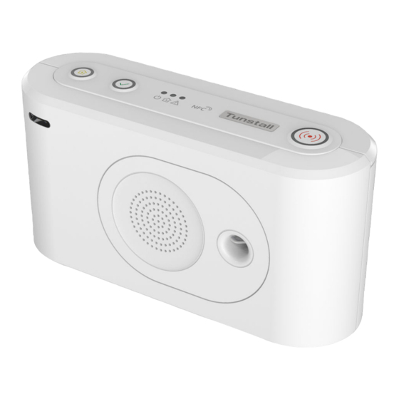
Page 16: Front/Top View
3.2. Front/top view 1. Yellow Extra button 5. Yellow LED indicator 9. Microphone 2. Green Cancel button 6. Red LED indicator 10. IR receiver 3. Red Alarm button 7. NFC 11. Speaker 4. Green LED indicator 8. Back cover... -
Page 17: Rear-View
3.3. Rear-view 1. On/Off (I/0) switch 5. Stub antenna 9. SIM card holder inside battery slot 2. Antenna connector 6. Cable slot 10. 2x USB 2.0 ports 3. Ethernet/network connector 7. Security screw (T10) for battery (RJ45 port) slot 4. Power connector 12V (RJ11 port) 8. -
Page 18: Button Functions
3.4. Button functions 1. Red Alarm button 2. Green Cancel button 3. Yellow Extra button Mode Button Function Press the red Alarm button Activate alarm/make alarm call Press the green Cancel button Cancel alarm Cancel call back Cancel At Source Cancel system warning announcement Press and hold the green Cancel button for 3 seconds Toggle Home/Away mode... -
Page 19: Button Leds
3.5. Button LEDs 1. Red Alarm button 2. Green Cancel button 3. Yellow Extra button Indication Status Red Alarm button LED on Standby mode Red Alarm button LED flashing (0.5s on/4.5s off) Standby mode on backup battery Red Alarm button LED flashing (0.5s on/0.5s off) Connection attempt Red Alarm button LED flashing (1s on/1s off) Pausing between connection attempts... -
Page 20: Led Indicators
3.6. LED indicators 1. Red LED indicator 2. Yellow LED indicator 3. Green LED indicator Indication Status Green LED on Standby mode Green LED flashing, (0.5 s on/ 4.5 s off) Standby mode on backup battery Green LED flashing (0.5 s on/ 0.5 s off) Connection attempt Green LED flashing (1 s on/1 s off) Pausing between connection attempts... - Page 21 Announcement Description "Warning" Warning announcement that is followed by a warning message "There is no mains power" AC power to the device is lost "Mains power is restored" AC power to the device is restored "Battery low" The backup battery is low "Reduction in radio range detected"...
-
Page 22: Tx4 Alarm Button/Pendant
• the red LED (2) lights up to indicate that the Tx4 is sending a radio signal to the Lifeline Digital. • the red LED (2) flashes to indicate that the battery is low and that Tx4 is sending a radio signal to the Lifeline Digital. -
Page 23: Installation
Before installation, the device must be prepared for active use: • If the device is prepared and configured within Tunstall's Device Management Platform (DMP), either download the settings prior to on-site installation or make sure that the settings are ready for download from DMP during the installation process. -
Page 24: Connect And Install Lifeline Digital
(3). 4.1.3. Install SIM card Lifeline Digital is typically delivered with a pre-installed mini-SIM card. However, if you need to insert or replace the SIM card, see Insert or replace the SIM card, page 99. 4.1.4. Connect the Ethernet cable NOTE The Ethernet cable is not supplied by Tunstall. -
Page 25: Connect A Usb
4.1.6. Connect to mains power CAUTION Only use a power adapter that is intended for use with this product and that has been supplied by Tunstall. Make sure that the power adapter has the following output specification: • +12.0V 1.0A, (12.0W) PIN 2“+”... -
Page 26: Manually Connect To Dmp
The device is ready when the LED indicators stop flash- ing. 4.1.8. Manually connect to DMP If the device is registered to Tunstall's Device Management Platform (DMP), you can manually connect to DMP to download configuration or firmware updates. To manually connect to DMP: Press and hold the yellow Extra button (1) for approxi- mately 3 seconds. - Page 27 When installation, configuration and testing is comple- ted, remove the adhesive cover from the back of the antenna (2) and fix the antenna in the selected location (3). The location must be: • A non-metallic surface • Indoors, the antenna is not water-resistant...
-
Page 28: Configuring Lifeline Digital In Programming Mode
4.2. Configuring Lifeline Digital in programming mode 4.2.1. Enable programming mode To enable programming mode: Press and hold the green Cancel button (1), then press and hold the red Alarm button (2) and the yellow Extra button (3). Release all buttons when the device emits a rising sound signal and announces "Programming mode”. - Page 29 want to select according to the Local configuration menu, page 29. Press the green Cancel button to exit programming mode. Menu position Announce- Description Section ment Yellow Extra button "One" Adjust speaker volume Adjust speaker volume, page 41 "Two" Adjust LED intensity Adjust LED intensity, page 42 "Three"...
-
Page 30: Checking Cellular Signal Strength
4.3. Checking cellular signal strength This section describes how to check cellular signal strength. The cellular signal strength test is required for all devices that communicate across cellular communication paths. 4.3.1. Check cellular signal strength To check cellular signal strength: Enable programming mode, see Enable programming mode, page 28. -
Page 31: Checking Cellular Network Status
4.4. Checking cellular network status This section describes how to check cellular network information. This information can be used to troubleshoot cellular connectivity issues. 4.4.1. Check cellular network error code To check the cellular network error code: Enable programming mode, see Enable programming mode, page 28. -
Page 32: Check Network Status
When the device announces “Two”, release the button. The device announces: • “SIM card status Zero” if no SIM card status is present. • “SIM card status One” if no PIN is required and the SIM card is OK. • “SIM card status Two” if PIN and SIM card are OK. •... -
Page 33: Check Cellular Radio Technology (Rat)
Press the green Cancel button (2) to exit. 4.4.4. Check cellular radio technology (RAT) To check cellular radio technology (RAT): Enable programming mode, see Enable programming mode, page 28. Press and hold the yellow Extra button (1). When the device announces “Five”, release the button. Press and hold the yellow Extra button (1). -
Page 34: Connecting And Disconnecting Peripherals
4.5. Connecting and disconnecting peripherals This section describes how to connect and disconnect peripherals. Lifeline Digital supports up to 64 peripherals. NOTE The personal alarm trigger is typically connected to the device on delivery. Connecting There are two basic methods of connecting peripherals in programming mode: 1. -
Page 35: Disconnect A Peripheral In Auto Pairing Mode
• “Error code Two” if the peripheral is already connec- ted to the device. Repeat from step b to connect additional peripherals. Press the green Cancel button (3) to save current set- tings and exit. Activate/trigger the peripheral to make a test alarm to the device, press the green Cancel button to cancel the alarm before the alarm is distributed to the receiver. -
Page 36: Connect A Peripheral In Manual Pairing Mode
Press the green Cancel button (4) to save current set- tings and exit. 4.5.3. Connect a peripheral in manual pairing mode To connect a peripheral in manual pairing mode: Enable programming mode, see Enable programming mode, page 28. Press and hold the red Alarm button (1). The device announces “Auto pairing mode”... -
Page 37: Disconnect A Peripheral In Manual Pairing Mode
Press the green Cancel button (3) to save current set- tings and exit. Activate/trigger the peripheral to make a test alarm to the device, press the green Cancel button to cancel the alarm before the alarm is distributed to the receiver. 4.5.4. - Page 38 Press the green Cancel button (3) to save current set- tings and exit.
-
Page 39: Testing The Radio Range Of Peripherals
4.6. Testing the radio range of peripherals This section describes how to use the Radio test mode to test the radio range of peripherals. Each connected peripheral must be tested in its intended location. Wearable peripherals such as alarm buttons/pend- ants must be tested throughout the premises to ensure complete range coverage. - Page 40 Press the green Cancel button (3) to exit the radio test or the radio test automatically ends after approx. 60 seconds.
-
Page 41: Adjusting Speaker Volume
4.7. Adjusting speaker volume Adjust the speaker volume if it is too low or too loud for the care recipient. The volume setting applies to all audio, including call volume, audio signals and announcements. 4.7.1. Adjust speaker volume To adjust speaker volume: Enable programming mode, see Enable programming mode, page 28. -
Page 42: Adjusting Led Intensity
4.8. Adjusting LED intensity Adjust the LED brightness if it is too bright or too dark for the care recipient. 4.8.1. Adjust LED intensity To adjust LED intensity: Enable programming mode, see Enable programming mode, page 28. Press and hold the yellow Extra button (1). When the device announces "Two", release the button. -
Page 43: Connecting And Disconnecting Nexa Smart Plugs
Smart plug, and an "OFF" code to disconnect the Smart plug. The Smart plug does not transmit to Lifeline Digital. Lifeline Digital supports up to 16 actuator output channels. More than one Nexa Smart plug can be associated with one channel. -
Page 44: Disconnect A Nexa Smart Plug In Actuator Pairing Mode
Press the green Cancel button (4) to exit. 4.9.2. Disconnect a Nexa smart plug in actuator pairing mode NOTE To simplify this procedure, connect a light to the Smart plug. When the Smart plug is unpaired from the device, the light will remain switched off. To disconnect a Smart plug: Unplug the Smart plug from the wall socket. - Page 45 Press the green Cancel button (5) to exit.
-
Page 46: Testing The Installation
• If applicable, fix the external antenna to a location with excellent coverage, see Connect the external cellular antenna (option), page 26 • Replace the back cover, see Remove and replace the back cover, page 24 • Make sure that the care recipient and caregivers understands how to use Lifeline Digital and any associated equipment... - Page 47 Lifeline Digital is now ready to use.
-
Page 48: Configuring Lifeline Digital Using Dmp
5. Configuring Lifeline Digital using DMP This chapter describes how to configure Lifeline Digital using Tunstall's Device Management Platform (DMP). Make sure that you have read the document and are familiar with the installation and configuration process. Typically, not all sections in this document will be relevant to your case. Omit sections and settings that are already pre-config- ured or does not apply to your case. - Page 49 • Search the list by entering a text in the search field • Sort the list by clicking a column header. Click again to toggle between ascending and descending order • Filter the list by selecting an option in the drop-down list below a column heading •...
-
Page 50: Common Settings
5.2. Common settings Common settings contains basic device and connectivity settings. To configure or change these settings you require a list of which settings to amend, together with their required values. This information is typically provided to you by your organization. 5.2.1. -
Page 51: Configuring Communication Settings
5.3. Configuring communication settings This section describes how to set up and configure communication between Lifeline Digital and the designated alarm receivers or Alarm Receiving Centres (ARCs): 1. Configure connectivity settings, including connectivity method (Ethernet or cellular), APN for cellular data and a telephone number for cellular callback: •... -
Page 52: Select Device Connectivity Methods
• WiFi 5.3.1.2. Configure cellular network settings and Access Point Name (APN) CAUTION Do not change settings or values unless advised by your supplier or Tunstall. Unauthorized changes may disrupt communication and cause connectivity failure. To configure cellular network settings: Go to IP Alarms >... -
Page 53: Register A Telephone Number For Callback
5.3.1.3. Register a telephone number for callback To register a telephone number for callback: Go to Common settings. Enter the telephone number to use for cellular callback in the Callback phone number field. NOTE Use international telephone number format, for example: "+46[...]" or "0046[...]". 5.3.2. -
Page 54: Configure Ip Alarm Connections
5.3.2.2. Configure IP Alarm connections CAUTION Do not change settings or values unless advised by your supplier or Tunstall. Unauthorized changes may disrupt communication and cause connectivity failure. To configure connection details for IP Alarms: Go to IP Alarms > Connections and select an appropriate Address. Address n is typically reserved for night redirection. -
Page 55: Configure Sip Accounts
5.3.2.3. Configure SIP accounts CAUTION Do not change settings or values unless advised by your supplier or Tunstall. Unauthorized changes may disrupt communication and cause connectivity failure. If required by the alarm receiver or Alarm Receiving Centre (ARC), to configure SIP accounts: Go to IP Alarms >... -
Page 56: Configure Analog Alarm Connections
5.3.2.4. Configure Analog alarm connections CAUTION Do not change settings or values unless advised by your supplier or Tunstall. Unauthorized changes may disrupt communication and cause connectivity failure. To configure connection details for analog alarms: Go to Analog Alarms. Select an appropriate Address analog alarm tab to expand the view. The Address analog alarm N tab is typically reserved for night redirection. -
Page 57: Configuring Call Sequences
If you need to amend these settings, you require a list of the parameter settings and values to be configured. 5.3.3.1. Configure call sequences CAUTION Do not change settings or values unless advised by your supplier or Tunstall. Unauthorized changes may disrupt communication and cause connectivity failure. To configure sequences: Go to Call Sequence. - Page 58 Select an appropriate Sequence to expand the view. Select a sequence type in the drop-down list of each step to be included in the current sequence: • Lowercase letters (“a, b, c”) correspond to the addresses in the IP Alarms tab •...
-
Page 59: Configure Sequences Per Event Group
5.3.3.2. Configure sequences per event group CAUTION Do not change settings or values unless advised by your supplier or Tunstall. Unauthorized changes may disrupt communication and cause connectivity failure. To select sequences for event groups: Go to Call Sequence. Click Sequence per event group to expand the view. -
Page 60: Setting Up An Access Point (Lifeline Digital As Access Point)
Enter the name of the network you want to connect to in the SSID field. Enter the password of the network in the Pre shared key field. 5.3.4.2. Setting up an access point (Lifeline Digital as access point) To set up an access point: Go to IP Alarms >... -
Page 62: Configuring Time Settings
5.4. Configuring time settings 5.4.1. Set the time zone To set the time zone: Go to Time. Under Real Time Clock & Time Zone, select the correct time zone in the Time zone drop-down list. If automatic daylight saving time is required, tick the Use automatic daylight saving time for local time checkbox. If +1 hour offset is required, tick the Use default time compensation of +01.00 for local time checkbox. -
Page 63: Configuring Power Settings
Under Interval Stop, select a day of the week or every day in the Weekday drop-down list and set the Hours (0-23), Minutes (0-59) and Seconds (0-59) fields to set the stop time for the interval. 5.5. Configuring power settings 5.5.1. -
Page 64: Configuring Speaker Volume And Led Intensity
5.6. Configuring speaker volume and LED intensity The speaker volume and the intensity of the keypad LEDs should be adjusted to fit the requirements of the care recipient. The volume setting applies to all audio, including call volume, audio signals and announcements. However, speech messages have additional volume settings. -
Page 65: Configure Led Dimmer
5.6.3. Configure LED dimmer To configure LED dimmer : Go to LED and warnings. Under LED dim control, select an activation option in the Activation drop-down list: • Not activated • Always active • Active when associated Time Schedule Control (TSC) output is active If TSC is used for activation, select which TSC to use in the TSC drop-down list. -
Page 66: Configuring Settings For Incoming And Outgoing Calls
5.7. Configuring settings for incoming and outgoing calls 5.7.1. Configure settings for outgoing call To configure settings for outgoing calls: Go to Calls > Outgoing calls. Under Outgoing calls, select activation option for pre-alarm signal in the Pre alarm signal drop-down list: •... -
Page 67: Configure Callback Whitelisting
5.7.3. Configure callback whitelisting To configure callback whitelisting: Go to Calls > Callback whitelisting. Tick the Enable whitelisting checkbox to enable whitelisting. If required, tick the Bypass whitelisting if callback is active checkbox to bypass the whitelist if an alarm or event has triggered a callback. -
Page 68: Configuring Peripherals
However, not all settings in this section are available for every type of radio sensor. This section is primarily provided for reference. Tunstall strongly recommends that all new peripherals are connected manually. Only then amend settings or values if advised by your supplier or Tunstall. - Page 69 The radio code is typically printed on a label attached to the peripheral. The decimal radio code is used for "Connected radio (two-way)" (for example: 55.11.84.191), trinary for "Connected radio legacy (two-way)" (for example: 33112231) and six-digits for "Tunstall Classic (one-way)" (for example: 256449).
-
Page 70: Delete A Radio Sensor
The selected radio sensor is suppressed when this function is active. However, technical events that are critical for device monitoring are exempt from suppression. 5.8.2. Delete a radio sensor To delete a radio sensor record from Lifeline Digital: Go to Radio sensor. -
Page 71: Enable Pendant Signalling During Alarm Calls
Click on the sensor that you want to delete. Click Delete sensor in the Confirm delete dialogue box. The sensor is removed from the Radio tab. 5.8.3. Enable pendant signalling during alarm calls To enable pendant signalling during alarm calls: Go to Telecare >... -
Page 72: Configuring Device Monitoring Features
5.9.1. Periodic test alarm The periodic test alarm checks the connection between Lifeline Digital and the Alarm Receiving Centre (ARC) at regular intervals. If the ARC does not receive a periodic test alarm from a device as expected, an alarm is generated. -
Page 73: System Warnings
• Recurrent. If a link test failure is registered by the system, an alarm is generated every time the reload interval expires, until a successful link test transmission is detected. • Return function. The system generates an alarm when a successful link test transmission is detected. •... -
Page 74: Heartbeats And Online Polls
5.9.4. Heartbeats and online polls Lifeline Digital sends heartbeats and online polls to Tunstall’s Device Management Platform (DMP) at regular intervals: • Heartbeats contain data about the status of the device. An alternative interval can be enabled to conserve energy when the device is operating on backup batteries. -
Page 75: Set Interval For Online Poll
The alternative interval for heartbeats (online ping) is activated when the device switches to backup batteries. 5.9.4.2. Set interval for online poll CAUTION Do not change settings or values unless advised by your supplier or Tunstall. Unauthorized changes may disrupt communication and cause connectivity failure. To set the interval for online poll: Go to Time >... - Page 76 Select whether or not the device notifies the Alarm Receiving Centre (ARC) when the mains power return in the Mains return alarm drop-down list • Activated. The function is active. • Not activated. The function is not active...
-
Page 77: Configuring Telecare Features
5.10. Configuring telecare features Lifeline Digital has several advanced telecare features that can be customized to fit individual care requirements. 5.10.1. Home/Away The Home/Away feature is used to notify the system and the Alarm Receiving Centre (ARC) when the care recipient is away (or home). -
Page 78: Speech Messages
Under Presence, set the maximum duration for Presence mode in the Maximum time (hours) field. When the maximum time has elapsed, Presence mode is automatically deactivated. 5.10.3. Speech messages Speech messages are audio announcements that acknowledge an action or alert the care recipient or caregiver that a certain action is required. -
Page 80: Basic Inactivity (Bia) Monitoring
5.10.4. Basic Inactivity (BIA) monitoring The Basic Inactivity (BIA) monitoring function is used to ensure that a person, who has unexpectedly become incapaci- tated and unable to trigger an alarm call, is visited or called as soon as possible following a preset time period. For example, after 24 hours at the latest. -
Page 81: Enable Bia Monitoring On The Yellow Button
5.10.4.2. Enable BIA monitoring on the yellow button NOTE BIA monitoring is typically assigned to the yellow Extra button. To enable BIA monitoring on the yellow Extra button: Go to Telecare > Other Under Yellow button, select Inactivity in the Event type for yellow button drop-down list. The inactivity timer is reset when the yellow Extra button is pressed. -
Page 82: Temperature Guard
Under CAS options, the following options are available: • Dementia mode. Tick this checkbox to prevent the system from generating multiple alarms of the same type that caused the initial CAS alarm 5.10.6. Temperature guard The temperature guard monitors the ambient temperature and notifies the Alarm Receiving Centre (ARC) if the temperature falls below or rises above the pre-configured limits. -
Page 83: Configure Temperature Guard - High Temperature Alarm
Select a pre-configured channel in the Actuator output channel drop-down list. NOTE Internal hardwired output is only available in the Extended variant. 5.10.6.2. Configure temperature guard - high temperature alarm NOTE This section describes how to configure the integral temperature sensor. To configure the temperature guard for high temperature alarm: Go to Telecare >... -
Page 84: Emergency
5.10.7. Emergency The Emergency feature allows a caregiver to send an emergency alarm via Lifeline Digital using a personal alarm trigger. 5.10.7.1. Enable Emergency feature To enable Emergency feature: Go to Telecare > Other. Under Emergency, assistance, select an activation option in the Emergency active drop-down list: •... -
Page 85: The Yellow Button
• Activated NOTE Assistance is only available when the system is in Presence mode. 5.10.9. The yellow button The yellow Extra button is typically used by the care recipient to register activity for Basic Inactivity (BIA) monitoring. However, it is possible to assign other types of alarms or events to the button. 5.10.9.1. - Page 86 ◦ Manually connect to DMP on the green Cancel button.
-
Page 87: Configuring The Smart Sensor Platform
5.11. Configuring the Smart sensor platform The Smart sensor platform provides dynamic features that combine sensors, timers and actuator control. These features can typically be scheduled for when and for how long they are active or inactive. 5.11.1. Virtual Intelligent Bed Sensor (VIBS) The Virtual Intelligent Bed Sensor (VIBS) monitors when a care recipient is in bed and out of bed. - Page 88 The activation time starts when the care recipient gets out of bed. If the care recipient returns to bed before the activation time has elapsed, no alarm is generated. iii. Set the initial absence time to delay VIBS activation in the Initial absence time (seconds) field. The initial absence time delays VIBS activation in case the care recipient goes to bed later than expected.
- Page 89 Under Activation timer reset trigger, to enable the reset trigger: Select a sensor in the Radio sensor drop-down list. Select None if the reset trigger is not required. If required, select sensor trigger type in the Trigger type drop-down list. Otherwise, select “Any” to keep settings from the selected radio sensor.
-
Page 90: Virtual Intelligent Property Sensor (Vips)
Under Light control, configure actuator control and timers: Select a channel with a pre-configured Smart plug in the Light control output channel field. Set the run-on timer in the Light control run-on timer (seconds) field. The timer starts when a care recipient gets into bed and switches off the light when it elapses. iii. - Page 91 Enable VIPS Under Virtual Intelligent Property Sensor select an activation option in the Activation drop-down list: • Not activated • Always active • Active when the system is in Away mode • Active when the system is in Home mode •...
- Page 92 Under Door Sensor > Door Close, enable the door sensor to detect when the door closes: Select the door sensor in the Radio sensor drop-down list. If required, select sensor trigger type in the Trigger type drop-down list. Otherwise, select “Any” to keep settings from the selected radio sensor.
-
Page 93: Actuator Control
Lifeline Digital currently supports Nexa Smart plugs. Unlike other types of peripherals, the Smart plug does not transmit to Lifeline Digital. Instead, Lifeline Digital sends an "On" or "Off" transmission to switch on or off the Smart plug. -
Page 94: Enable Led Indication When The Microphone Is Turned On
5.11.3.2. Enable LED indication when the microphone is turned on To enable LED indication when the microphone is turned on: Go to Input/Output > Actuator control. Enter value "250" in the Channel for external actuator control field to select the red LED channel. Select "Mic activation"... -
Page 95: Advanced Settings
5.12. Advanced settings Access to advanced settings is determined by permission profiles and environment settings. Therefore, some settings and pages may not be available to you or may be display differently than described in this document. 5.12.1. Disable pendant battery check To disable pedant battery check Go to Advanced >... -
Page 96: Save Device Settings
5.13. Save device settings To save device settings: When you have amended all required settings, click Save. DMP displays a list of the accumulated changes. If necessary, click Cancel to amend any setting. Click Save to save changes. DMP displays a verification message. Click Verify. -
Page 97: Maintenance And Cleaning
6.2. Replace the backup batteries WARNING Risk of explosion if battery is replaced by an incorrect type. Only use batteries supplied and fitted by Tunstall. Dispose of used batteries according to current local regulations. Required tool: T10 torx screwdriver. To replace the backup batteries: Remove the back cover. -
Page 98: Replacing The Battery In The Tx4 Alarm Button/Pendant
Keep batteries out of reach of children. Swallowing a battery can be life-threatening. Seek immediate medical attention if this happens. CAUTION Only use new and unused battery kits from Tunstall. Do not reuse old parts as this can affect the water and dust protection. To replace the battery in the Tx4 sensor: Remove the Tx4 from the wearing option (1). -
Page 99: Insert Or Replace The Sim Card
Cancel button before the alarm call is distributed to an alarm receiver. 6.4. Insert or replace the SIM card NOTE Lifeline Digital uses only mini-SIM cards. Required tools: T10 torx screwdriver. To insert or replace the SIM card: Remove the back cover. -
Page 100: Cleaning And Disinfecting Lifeline Digital
Do not spray cleaning agents or disinfectants directly onto Lifeline Digital. Clean Lifeline Digital and pendant with a soft cloth or soft brush. Clean stubborn dirt with a soft, damp cloth. Only use a mild, diluted cleaning agent in exceptional cases. Use non-alcoholic disinfectants for hand-damp wipe disinfection of Lifeline Digital and pendant. - Page 101 Replace missing accessories and enclosed short user guide. Configure Lifeline Digital for the new user and migrate it in the DMP to a district of devices in use, see DMP user manual.
-
Page 102: Disposal And Recycling
Keep batteries out of reach of children. Swallowing a battery can be life-threatening. Seek immediate medical attention if this happens. WARNING Risk of explosion if battery is replaced by an incorrect type. Only use batteries from Tunstall. Dispose of used batteries according to current local regulations. -
Page 103: Startup Mode
Appendix A. Startup mode 1. Startup mode Startup mode provides shortcuts to certain functionality. Startup mode is enabled by holding down a button on the keypad when the device is powered up: • Press and hold down the red Alarm button to connect or disconnect telecare peripherals. •... -
Page 104: Connect A Peripheral In Startup Mode
Menu position Announcement Description Yellow Extra button "One" Adjust speaker volume "Two" Adjust LED intensity "Three" Radio test mode "Four" Test cellular signal strength "Five" Cellular status "One" Error code (default) "Two" Check SIM card status "Three" Check cellular network status "Four"... -
Page 105: Disconnect A Peripheral In Startup Mode
Activate/trigger the peripheral you want to connect (3). The device emits a beep and then a rising sound signal to acknowledge that the radio code is received and stor- • A short beep indicates that the accessory has been installed. •... -
Page 106: Connect A Nexa Smart Plug In Startup Mode
Switch on the device (2). When the device emits four consecutive beeps, release the button. Trigger the peripheral you want to test (3): • One short beep indicates that the peripheral is con- nected and the battery is OK. • One long beep indicates that the peripheral is con- nected but the battery is low and must be replaced. -
Page 107: Disconnect A Nexa Smart Plug In Startup Mode
The device starts to emit consecutive beeps to indicate that actuator pairing mode is active. Insert the Smart plug into a wall socket (4). The Smart plug switches on and off a couple of times (5). The Smart Plug remains switched on when the pairing is completed. -
Page 108: Service Menu
Insert the Smart plug into a wall socket (5). The Smart plug switches on and off a couple of times (6). The Smart Plug remains switched off when the unpairing is completed. If a light is connected to the Smart plug, the light will remain switched off when the Smart plug is unpaired from the device. - Page 109 ◦ Red LED indicator on - backup battery is charging ◦ Red LED indicator off - backup battery is not charg- Restart Lifeline Digital manually by turning it off and then on again to switch off the battery charging sta- tus.
-
Page 110: Programming Mode Diagram
Appendix B. Programming mode diagram Standby mode Programming mode - Local configuration menu Adjust speaker volume Radio sensor Radio sensor Auto pairing mode Adjust LED intensity Radio sensor Manual pairing mode Radio sensor Radio sensor Radio test mode Test cellular signal strength Cellular status Cellular error code Check SIM status... -
Page 111: Events And Event Distribution
Appendix C. Events and event distribution 1. Event codes and alarm types The device uses internal normalized event codes as described in the table below. These event codes are converted to specific communication protocol events for distribution to the alarm receiver or Alarm Receiving Centre (ARC). Event code Event ID Description... - Page 112 Event code Event ID Description Event group Event group ID Reporting-call-reset User has pressed the cancel button during a callback session, Call reporting i.e. callback session is cancelled. Reporting-call-busy Legacy event code used for Careline protocol Call reporting Door-opening-with- Door usage – opening. (Same as #9, but with indication that User alarm speech speech is required)
- Page 113 Event code Event ID Description Event group Event group ID Cooker Cooker guard activation Medium prio auto sen- sors Enuresis Enuresis sensor activation Medium prio auto sen- sors Window Window sensor activation Medium prio auto sen- sors Chair Chair sensor activation Medium prio auto sen- sors Refrigerator...
- Page 114 Event code Event ID Description Event group Event group ID Fall detector-fall risk Fall detector has detected risk for fall – level 5 Predictive level 5 PIR entry-exit PIR sensor activated – entry/exit Medium prio auto sen- sors PIR-non-entry-exit PIR sensor activated – non entry/exit Medium prio auto sen- sors PIR-tamper...
-
Page 115: Event Groups
2. Event groups Event groups contain groups of logically related event codes. Alarm distribution settings can be applied to the event group instead of every individual event code. Event group Description User alarm Main event group for user alarms, such as when a care recipient has pressed the red alarm button. (Previous- ly known as “Medical”) Inactivity Group for inactivity alarms/passive events. -
Page 116: Event Group Distribution Parameters
3. Event group distribution parameters Each event group has individual parameters that control event and alarm distribution. The table below describes the available parameters. Group No. Option Description Use defaults: Use hard coded default values for option 1:1-1:7 Allow mic: Allow microphone to be enabled during the alarm call Allow speaker: Allow speaker to be enabled during the alarm call... -
Page 117: Default Event Group Distribution Parameters
4. Default event group distribution parameters Each event group has individual parameters that control event and alarm distribution. The table below describes the default event group parameters. Event group Default distribution parameters User alarm Sequence: Priority: 255 (=default, hard coded to prio 1) Use defaults: Allow mic: Allow speaker:... - Page 118 Event group Default distribution parameters Use defaults: Allow mic: Allow speaker: Allow reset: Audible reassurance: Visual reassurance: Allow in Homephone: Inactivity input: Use defaults: Allow pre-call signal: Answer call: Allow when home: Allow when away: Allow in presence: Allow in ready: Actuator output: Use defaults: Postpone in callback:...
- Page 119 Event group Default distribution parameters Inactivity input: Use defaults: Allow pre-call signal: Answer call: Allow when home: Allow when away: Allow in presence: Allow in ready: Actuator output: Use defaults: Postpone in callback: Keep and postpone: Cancel At Source: 3:4-3:7 Spare: Spare parameters reserved for future use Care reporting...
- Page 120 Event group Default distribution parameters Allow in ready: Actuator output: Use defaults: Postpone in callback: Keep and postpone: Cancel At Source: 3:4-3:7 Spare: Spare parameters reserved for future use Emergency Sequence: Priority: 255 (=default, hard coded to prio 2) Use defaults: Allow mic: Allow speaker: Allow reset:...
- Page 121 Event group Default distribution parameters User defined Sequence: Priority: 255 (=default, hard coded to prio 6) Use defaults: Allow mic: Allow speaker: Allow reset: Audible reassurance: Visual reassurance: Allow in Homephone: Inactivity input: Use defaults: Allow pre-call signal: Answer call: Allow when home: Allow when away: Allow in presence:...
- Page 122 Event group Default distribution parameters Visual reassurance: Allow in Homephone: Inactivity input: Use defaults: Allow pre-call signal: Answer call: Allow when home: Allow when away: Allow in presence: Allow in ready: Actuator output: Use defaults: Postpone in callback: Keep and postpone: Cancel At Source: 3:4-3:7 Spare:...
- Page 123 Event group Default distribution parameters Allow when away: Allow in presence: Allow in ready: Actuator output: Use defaults: Postpone in callback: Keep and postpone: Cancel At Source: 3:4-3:7 Spare: Spare parameters reserved for future use Call reporting Sequence: Priority: 255 (=default, hard coded to prio 5) Use defaults: Allow mic: Allow speaker:...
- Page 124 Event group Default distribution parameters Cancel At Source: 3:4-3:7 Spare: Spare parameters reserved for future use Intrusion Sequence: Priority: 255 (=default, hard coded to prio 4) Use defaults: Allow mic: Allow speaker: Allow reset: Audible reassurance: Visual reassurance: Allow in Homephone: Inactivity input: Use defaults: Allow pre-call signal:...
- Page 125 Event group Default distribution parameters Allow reset: Audible reassurance: Visual reassurance: Allow in Homephone: Inactivity input: Use defaults: Allow pre-call signal: Answer call: Allow when home: Allow when away: Allow in presence: Allow in ready: Actuator output: Use defaults: Postpone in callback: Keep and postpone: Cancel At Source: 3:4-3:7...
- Page 126 Event group Default distribution parameters Answer call: Allow when home: Allow when away: Allow in presence: Allow in ready: Actuator output: Use defaults: Postpone in callback: Keep and postpone: Cancel At Source: 3:4-3:7 Spare: Spare parameters reserved for future use Defines which sequence to use for event distribution.
-
Page 127: Event Code Mapping Scaip
5. Event code mapping SCAIP The device uses internal normalized event codes as described in the table below. These event codes are converted to specific communication protocol events for distribution to the alarm receiver or Alarm Receiving Centre (ARC). The table below describes the mapping of normalized event codes to SCAIP protocol events. Event Event ID SCAIP <dtc>... - Page 128 Event Event ID SCAIP <dtc> SCAIP <stc> Service Temperature-low 0002 (Local Unit/Controller) 0101 (Temperature low) Extern-reminder Extern-med-reminder Medication dispenser-missed 0011 (Pill dispenser) 0081 (Pill not taken) Linktest-fail5 0002 (Local Unit/Controller) 0123 (Radio test missing) Linktest-fail6 0002 (Local Unit/Controller) 0123 (Radio test missing) Linktest-fail7 0002 (Local Unit/Controller) 0123 (Radio test missing)
- Page 129 Event Event ID SCAIP <dtc> SCAIP <stc> Bed/Chair-not up 0012 (Bed sensor) 0117 (Lying in bed) Bed/Chair-absence 0012 (Bed sensor) 0003 (Absent) Fall detector-button 0005 (Fall detector) 0010 (Alarm manual) Fall detector-not worn 0005 (Fall detector) 0049 (Inactive) Fall detector-cancelled 0005 (Fall detector) 0093 (Reset manual) Fall detector-fall risk level 1...
-
Page 130: Event Code Mapping Ipacs
6. Event code mapping IPACS The device uses internal normalized event codes as described in the table below. These event codes are converted to specific communication protocol events for distribution to the alarm receiver or Alarm Receiving Centre (ARC). The table below describes the mapping of normalized event codes to IPACS protocol events. Event Event ID IPACS code (Dec) - Page 131 Event Event ID IPACS code (Dec) IPACS code (Hex) Service Temperature-low 0x88 Extern-reminder Extern-med-reminder Medication dispenser-missed 0x47 Linktest-fail5 0x55 Linktest-fail6 0x56 Linktest-fail7 0x57 Linktest-fail 0x58 Linktest-return1 0x61 Linktest-return2 0x62 Linktest-return3 0x63 Linktest-return4 0x64 Linktest-return5 0x65 Linktest-return6 0x66 Linktest-return7 0x67 Linktest-return8 0x68 Active-tagestaste 0x72...
- Page 132 Event Event ID IPACS code (Dec) IPACS code (Hex) Bed/Chair-absence 0xAB Fall detector-button 0xAC Fall detector-not worn 0xAD Fall detector-cancelled 0xAE Fall detector-fall risk level 1 0xAF Fall detector-fall risk level 2 0xB0 Fall detector-fall risk level 3 0xB1 Fall detector-fall risk level 4 0xB2 Fall detector-fall risk level 5 0xB3...
-
Page 133: Radio Sensor Events Per Trigger Type
Appendix D. Radio sensor events per trigger type Trigger Trigger type Radio sen- Event trigger Note type no. sor event (1-15) Basic personal trigger (MyAmie AP) Button pressed once Tx3/Tx4 trigger Button pressed once Button pressed twice Button pressed three times Input 1 activated Input 2 activated Premium personal trigger/wearable 9... - Page 134 Trigger Trigger type Radio sen- Event trigger Note type no. sor event (1-15) Bed other ADLIfe bed occupied ADLife bed unoccupied PIR entry/exit Activation Fall detector Button pressed Fall Fall detector not worn Cancel button pressed PIR standard Standard activation Entry/Exit activation Tamper Carer trigger...
- Page 135 Trigger Trigger type Radio sen- Event trigger Note type no. sor event (1-15) Activation Tx4 T-Box2 Input 1 activated Input 2 activated Tx4 PC (Pull Cord) Button pressed once (External button) Button pressed twice (External button) Button pressed three times (External button) Input 2 activated (Pull cord is activate)
-
Page 136: Homephone Protocol Commands
Appendix E. Homephone protocol commands When the homephone protocol is used to connect to a receiver, the receiver uses the keypad on the telephone to send commands to Lifeline Digital. Command Description 1, 3 Switch to simplex mode, change speech direction. -
Page 137: Technical Data
Lifeline Digital Tx4 (Black) EU 022-25-903 Lifeline Digital MyAmie ALB (White) UK 022-25-904 Lifeline Digital MyAmie AP (White) EU 022-25-905 Lifeline Digital MyAmie AP (Black) EU 022-25-908 Lifeline Digital (White) Tx4 915 (Grey) APAC 022-25-911 Lifeline Digital Tx4 (White) Sweden... -
Page 138: Technical Details Tx4
022-25-912 Lifeline Digital Tx4 (Black) Sweden Options 022-25-015-01 External antenna (White) 022-25-015-02 External antenna (Black) Time may be reduced by factors including temperature extremes, weak or intermittent cellular connectivity, high levels of sensor radio frequency activity and battery ageing. 2. Technical details Tx4... -
Page 139: Technical Details Myamie
MyAmie Auto Presence (AP) (White with red button) Time may be reduced by factors including temperature extremes, weak or intermittent connectivity and battery ageing. 4. Spare parts Article number Description Region 022-25-012 Backup battery Lifeline Digital Global 022-25-015-01 External antenna (white) Global 022-25-015-02 External antenna (black) -
Page 140: Contact Details
Appendix G. Contact details Australia info@tunstallnordic.com Tunstall New Zealand www.tunstall.fi 2/65 Chapel Street Tunstall Australasia Tauranga Unit 1 New Zealand 56 Lavarack Ave France Eagle Farm Mail Address: Queensland 4009 Tunstall New Zealand Zone Harfleur Australia PO Box 13153 90A Allee Hubert Curien... - Page 141 Vitaris Response B.V. Tunstall Healthcare (UK) Ltd www.tunstall.se Oslo 26 Whitley Lodge 2993 LD Barendrecht Whitley Bridge PO Box 311 Yorkshire 2990 AH Barendrecht DN14 0HR The Netherland The Netherlands United Kingdom Tunstall B.V. +31 55 539 54 00...
- Page 142 Tunstall does not accept responsibility for any errors and omissions within this document. Tunstall declare that this radio equipment is in compliance with Directive 2014/53/EU. The full text of the EU declara- tion of conformity is available at the following address: https://www.tunstall.com/lifeline-digital-documentation Transmitting power: The transmitted power in the actual frequency band is less than 1mW e.r.p.
Need help?
Do you have a question about the Lifeline Digital and is the answer not in the manual?
Questions and answers