Tunstall Lifeline Digital User Manual
Hide thumbs
Also See for Lifeline Digital:
- Installation manual (142 pages) ,
- User manual (67 pages) ,
- Quick install manual (16 pages)

Subscribe to Our Youtube Channel
Related Manuals for Tunstall Lifeline Digital


Summary of Contents for Tunstall Lifeline Digital
- Page 1 Lifeline Digital Art: 022-25-9xx User manual English Doc. 346 80 21-58. Version 1.1. Revision 01.2022...
-
Page 2: Table Of Contents
4.1.5. Switch on Lifeline Digital ....................... 19 4.1.6. Connect the external cellular antenna (region specific) ..............19 4.2. Configuring Lifeline Digital in programming mode ................20 4.2.1. Enable programming mode ......................20 4.2.2. Programming mode and local configuration menu ................. 20 4.3. - Page 3 D. LED indicator status ........................... 49 E. Programming mode diagram ........................50 F. Homephone protocol commands ........................ 51 7. Technical data ............................52 7.1. Technical details Lifeline Digital ......................52 7.2. Technical details Tx4 ........................... 53 7.3. Technical details MyAmie ........................53...
-
Page 5: Introduction
Lifeline Digital typically communicates over the 4G network with fallback to 3G and 2G if 4G is not available. Lifeline Digital supports VoLTE voice calls over the 4G network. -
Page 6: Communication Paths For Dmp
• Connect Lifeline Digital (1) to a local Wi-Fi network (2) to enable additional connectivity • Configure Lifeline Digital to act as an access point (AP). This configuration can be used to stream video from a sur- veillance camera (1) via the device (2) to an alarm receiver (3) 1.1.4. -
Page 7: Symbols Used In This Document
7. Technical data, page 52 for Lifeline Digital and included pendants 8. Appendices Some features may be configured differently than described in this document. Contact your supplier or Tunstall if you have any questions. 1.2.1. Symbols used in this document WARNING The warning symbol indicates a serious risk of damage to the equipment or personal injury. -
Page 8: Overview
2. Overview 2.1. What's in the box 1. Lifeline Digital 4. Tx4 alarm button/pendant (region specific) 2. Mains power adapter 5. MyAmie pendant (region specific) 3. External cellular antenna (region specific) Also included in the box: • Wrist strap and holder for Tx4 alarm button/pendant •... -
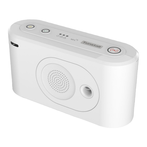
Page 9: Front/Top View
2.2. Front/top view 1. Yellow Extra button 5. Yellow LED indicator 9. Microphone 10. IR receiver 2. Green Cancel button 6. Red LED indicator 3. Red Alarm button 7. NFC 11. Speaker 4. Green LED indicator 8. Back cover 2.3. Rear-view 1. -
Page 10: Tx4 Alarm Button/Pendant
2.4. Tx4 alarm button/pendant 1. Push-button 2. Red LED indicator, indicates that the Tx4 sensor is transmitting 3. Green LED indicator, indicates that transmission has been received 2.5. MyAmie pendant 1. Push-button 2. Red LED indicator, indicates that the pendant is transmitting... -
Page 11: Using Lifeline Digital
ARC. The type of alarm or event determines which sequence to use for distribution. When an alarm call is initiated, the care recipient can use Lifeline Digital as a speakerphone to communicate with the alarm receiver or ARC operator. -
Page 12: Home/Away
• When Lifeline Digital announces "Press the Cancel but- ton to cancel the alarm", press the green Cancel button (1). The device announces "The alarm has been cancelled". 3.2. Home/Away The Home/Away feature is used to notify the system and the Alarm Receiving Center (ARC) when the care recipient is away (or home). -
Page 13: Cancel At Source (Cas)
To activate Presence mode: • Press and hold the green Cancel button (1) then press the red Alarm button (2) twice and release all buttons. The yellow LED indicator switches on to indicate that Presence mode is active. To activate Ready and deactivate Presence mode: •... -
Page 14: Basic Inactivity (Bia) Monitoring
This feature must be enabled. NOTE When Lifeline Digital is switched on, you must press the yellow Extra button to activate BIA monitor- ing. The yellow button LED slowly flashes (0.5 seconds on/ 9.5 seconds off) when Basic Inactivity (BIA) monitoring is ena- bled. -
Page 15: Emergency
3.6. Emergency The Emergency feature allows a caregiver to send an emergency alarm via Lifeline Digital using a personal alarm trig- ger. 3.6.1. Send Emergency alarm NOTE This feature must be enabled. To send an emergency alarm: • Trigger the personal (staff) alarm button/pendant. -
Page 16: System Warnings
When the device emits a rising sound signal and the yel- low LED indicator starts to flash, release the button. The device attempts to connect to DMP and announces either: • "Connected to DMP" when a connection is establish- • "Connection attempt to DMP failed" if all connection attempts fail. -
Page 17: Configuration And Testing
4. Configuration and testing This section describes how to configure and test Lifeline Digital using the buttons on the keypad. 4.1. Connecting Lifeline Digital 4.1.1. Remove and replace the back cover NOTE Only remove the back cover for installation, configuration, or maintenance. The back cover protects the device from tampering. -
Page 18: Connect A Usb
Insert the USB plug into an available USB port (1). 4.1.4. Connect to mains power CAUTION Only use power adapters supplied by Tunstall. To connect to mains power and power up: Insert the power adaptor cable into the 12V connector on the device (1). -
Page 19: Configuring Lifeline Digital In Programming Mode
The location must be: • A non-metallic surface • Indoors, the antenna is not water-resistant 4.2. Configuring Lifeline Digital in programming mode 4.2.1. Enable programming mode To enable programming mode: Press and hold the green Cancel button (1), then press and hold the red Alarm button (2) and the yellow Extra button (3). - Page 20 Select a function in Programming mode: • Press and hold the yellow Extra button until the de- vice announces the number of the menu position you want to select according to the Local configuration menu. For example, the device announces “One” for speak- er volume, “Two”...
-
Page 21: Checking Cellular Signal Strength
4.3. Checking cellular signal strength This section describes how to check cellular signal strength. The cellular signal strength test is required for all devices that communicate across cellular communication paths. 4.3.1. Check cellular signal strength To check cellular signal strength: Enable programming mode, see Enable programming mode, page 20. -
Page 22: Check Sim Card Status
Press and hold the yellow Extra button (1). When the device announces “Five”, release the button. Press and hold the yellow Extra button (1). When the device announces “One”, release the button. The device announces: • “Error code Zero” if there is no error code. •... -
Page 23: Check Network Status
When the device announces “Two”, release the button. The device announces: • “SIM card status Zero” if no SIM card status is present. • “SIM card status One” if no PIN is required and the SIM card is OK. • “SIM card status Two” if PIN and SIM card are OK. •... -
Page 24: Check Cellular Radio Technology (Rat)
Press the green Cancel button (2) to exit. 4.5. Connecting and disconnecting peripherals This section describes how to connect and disconnect peripherals. Lifeline Digital supports up to 64 peripherals. NOTE The personal alarm trigger is typically connected to the device on delivery. -
Page 25: Connect A Peripheral In Auto Pairing Mode
1. Connect in auto paring mode to store a peripheral in the first available radio sensor position, see Connect a pe- ripheral in auto pairing mode, page 26. 2. Connect in manual pairing mode to store a peripheral in a specific radio sensor position, see Connect a peripheral in manual pairing mode, page 28. -
Page 26: Disconnect A Peripheral In Auto Pairing Mode
Press the green Cancel button (3) to save current set- tings and exit. Activate/trigger the peripheral to make a test alarm to the device, press the green Cancel button to cancel the alarm before the alarm is distributed to the receiver. 4.5.2. -
Page 27: Connect A Peripheral In Manual Pairing Mode
Press the green Cancel button (4) to save current set- tings and exit. 4.5.3. Connect a peripheral in manual pairing mode To connect a peripheral in manual pairing mode: Enable programming mode, see Enable programming mode, page 20. Press and hold the red Alarm button (1). The device announces “Auto pairing mode”... -
Page 28: Disconnect A Peripheral In Manual Pairing Mode
Press the green Cancel button (3) to save current set- tings and exit. Activate/trigger the peripheral to make a test alarm to the device, press the green Cancel button to cancel the alarm before the alarm is distributed to the receiver. 4.5.4. -
Page 29: Testing The Radio Range Of Peripherals
Press the green Cancel button (3) to save current set- tings and exit. 4.6. Testing the radio range of peripherals This section describes how to use the Radio test mode to test the radio range of peripherals. Each connected peripheral must be tested in its intended location. Wearable peripherals such as alarm buttons/pend- ants must be tested throughout the premises to ensure complete range coverage. -
Page 30: Connecting And Disconnecting Nexa Smart Plugs
Smart plug, and an "OFF" code to disconnect the Smart plug. The Smart plug does not transmit to Lifeline Digital. Lifeline Digital supports up to 16 actuator output channels. More than one Nexa Smart plug can be associated with one channel. -
Page 31: Disconnect A Nexa Smart Plug In Actuator Pairing Mode
NOTE The red Alarm button toggles between sending the ON code and the OFF code: • The OFF code is indicated by consec- utive double beeps • The ON code is indicated by consec- utive beeps Insert the Smart plug into a wall socket (2). The Smart plug switches on and off a couple of times (3). -
Page 32: Adjusting Speaker Volume
Press the red Alarm button (2). The device announces "Erasing" and then emits consec- utive double beeps to indicate that it is sending the OFF code. NOTE The red Alarm button toggles between sending the ON code and the OFF code: •... -
Page 33: Adjusting Led Intensity
To adjust speaker volume: • Press the red Alarm button (2) to increase speaker vol- ume. • Press the yellow Extra button (1) to decrease the speaker volume. Press the green Cancel button (3) to save current set- tings and exit. 4.9. - Page 34 Press the green Cancel button (3) to save current set- tings and exit.
-
Page 35: Maintenance And Cleaning
Lifeline Digital does not contain any parts that are serviceable. 5.1. Replace the backup batteries WARNING Risk of explosion if battery is replaced by an incorrect type. Only use batteries from Tunstall. Dispose of used batteries according to current local regulations. Required tool: T10 torx screwdriver. -
Page 36: Replace Battery In The Tx4 Alarm Button/Pendant
CAUTION Only use new and unused battery kits from Tunstall. Do not reuse old parts as this can affect the wa- ter and dust protection. To replace battery in the Tx4, you require a new and unused battery kit from Tunstall. -
Page 37: Insert Or Replace The Sim Card
Cancel button before the alarm call is distributed to an alarm receiver. 5.3. Insert or replace the SIM card NOTE Lifeline Digital uses only mini-SIM cards. Required tools: T10 torx screwdriver. To insert or replace the SIM card: Remove the back cover. -
Page 38: Clean Lifeline Digital
Replace the back cover. Set the ON/OFF switch to 1 (ON) to power up the de- vice. 5.4. Clean Lifeline Digital Dust the device with a soft damp cloth. Make sure that no moisture goes through the speaker perforations. -
Page 39: Disposal And Recycling
Keep batteries out of reach of children. Swallowing a battery can be life-threatening. Seek immediate medical attention if this happens. WARNING Risk of explosion if battery is replaced by an incorrect type. Only use batteries from Tunstall. Dispose of used batteries according to current local regulations. -
Page 40: Startup Mode
Appendix A. Startup mode 1. Startup mode Startup mode provides shortcuts to certain functionality. Startup mode is enabled by holding down a button on the keypad when the device is powered up: • Press and hold down the red Alarm button to connect or disconnect telecare peripherals. •... -
Page 41: Disconnect A Peripheral In Startup Mode
1.2. Disconnect a peripheral in startup mode To disconnect a peripheral in Startup mode: Make sure that the device is switched off. Press and hold the red Alarm button (1). Switch on the device (2). When the device emits an undulating sound signal you can either: •... -
Page 42: Access Local Configuration Menu In Startup Mode
Trigger the peripheral you want to test (3): • One short beep indicates that the peripheral is con- nected and the battery is OK. • One long beep indicates that the peripheral is con- nected but the battery is low and must be replaced. •... -
Page 43: Connect A Nexa Smart Plug In Startup Mode
Menu position Announcement Description Yellow Extra button "One" Adjust speaker volume "Two" Adjust LED intensity "Three" Radio test mode "Four" Test cellular signal strength "Five" Cellular status "One" Error code (default) "Two" Check SIM card status "Three" Check cellular network status "Four"... -
Page 44: Disconnect A Nexa Smart Plug In Startup Mode
Insert the Smart plug into a wall socket (4). The Smart plug switches on and off a couple of times (5). The Smart Plug remains switched on when the pairing is completed. If a light is connected to the Smart plug, the light will re- main switched on when the Smart plug is paired to the device. - Page 45 Insert the Smart plug into a wall socket (5). The Smart plug switches on and off a couple of times (6). The Smart Plug remains switched off when the unpairing is completed. If a light is connected to the Smart plug, the light will re- main switched off when the Smart plug is unpaired from the device.
-
Page 46: Button Functions
Appendix B. Button functions 1. Red Alarm button 2. Green Cancel button 3. Yellow Extra button Mode Button Function Press the red Alarm button Activate alarm/make alarm call Press the green Cancel button Cancel alarm Cancel call back Cancel At Source Cancel system warning announcement Press and hold the green Cancel button for 5 seconds Toggle Home/Away mode... -
Page 47: Button Leds
Appendix C. Button LEDs 1. Red Alarm button 2. Green Cancel button 3. Yellow Extra button Indication Status Red LED on Standby mode Red LED flashing (0.5s on/4.5s off) Standby mode on backup battery Red LED flashing (0.5s on/0.5s off) Connection attempt Red LED flashing (1s on/1s off) Pausing between connection attempts... -
Page 48: Led Indicator Status
Appendix D. LED indicator status 1. Red LED indicator 2. Yellow LED indicator 3. Green LED indicator Indication Status Green LED on Standby mode Green LED flashing, (0.5 s on/ 4.5 s off) Standby mode on backup battery Green LED flashing (0.5 s on/ 0.5 s off) Connection attempt Green LED flashing (1 s on/1 s off) Pausing between connection attempts... -
Page 49: Programming Mode Diagram
Appendix E. Programming mode diagram Standby mode Programming mode - Local configuration menu Adjust speaker volume Radio sensor Radio sensor Auto pairing mode Adjust LED intensity Radio sensor Manual pairing mode Radio sensor Radio sensor Radio test mode Test cellular signal strength Cellular status Cellular error code Check SIM status... -
Page 50: Homephone Protocol Commands
Appendix F. Homephone protocol commands This is a list of commands for receivers that use the homphone protocol. The commands are send to Lifeline Digital using the telephone keypad. Command Description 1, 3 Switch to simplex mode, change speech direction. -
Page 51: Technical Data
7. Technical data 7.1. Technical details Lifeline Digital Weight 491g net weight Dimensions 180 x 58 x 98 mm (L x W x H) Mains power 230v AC (1.5 Watts, typical) Backup battery Rechargeable Lithium-ion battery, 18Wh, 2500mAh capacity (continually internally charged) -
Page 52: Technical Details Tx4
7.2. Technical details Tx4 Weight 16g net weight (without attachments) Dimensions H 13mm, Ø 35 mm (without attachments) Battery 3V Lithium CR2450 (replaceable) Battery lifetime Approx. 5 years or 30.000 alarm transmissions Radio frequencies 869.2125 MHz & 868.3000 MHz (frequency hopping) Radio power The transmitted power in the actual frequency band is less than 1mW e.r.p Connection... - Page 53 Tunstall does not accept responsibility for any errors and omissions within this document. Tunstall declare that this radio equipment is in compliance with Directive 2014/53/EU. The full text of the EU declara- tion of conformity is available at the following address: https://www.tunstall.com/lifeline-digital-documentation Radio power: The transmitted power in the actual frequency band is less than 1mW e.r.p...
Need help?
Do you have a question about the Lifeline Digital and is the answer not in the manual?
Questions and answers