Table of Contents
Advertisement
Advertisement
Table of Contents

Subscribe to Our Youtube Channel
Related Manuals for Tunstall ConnectCall


Summary of Contents for Tunstall ConnectCall
- Page 1 ConnectCall User Guide...
-
Page 2: Table Of Contents
Listening to call waiting using the LRH phone ................8 Activate door entry lock release using the LRH phone ..............8 Single/Multiple Tunstall IP DECT phone system ............8 Switching off-site using the IP DECT phone ................8 Switching on-site using the IP DECT phone ................8 Answering an alarm call using the IP DECT phone ..............8... - Page 3 Settings Menu ........................20 Access Control ........................21 Adding a fob ..........................21 Deleting a fob ..........................23 Advanced Menu ......................... 25 Restart Menu ..........................25 Record Menu ..........................26 Resident Name ........................26 Resident Message ........................26 Receivers..........................26 Door Panels ..........................
-
Page 4: Introduction
This user guide is designed to help Scheme Managers to understand and operate the basic operational features of ConnectCall for the different system versions. The operation of the telephone based systems differs slightly dependent on whether the system uses a Long Range Cordless, DECT handset, multiple DECT handsets or a mobile phone. -
Page 5: Main Features Explained
Main features explained Enhanced safety The provision of an auto GSM backup facility (optional) and a removable memory card means residents are further protected. Message waiting This feature enables Scheme Managers to leave messages for residents on their speech module. For example if the resident has a visitor when they are out then the scheme manager can leave a message for the resident rather than trying to remember. -
Page 6: Using The Telephone Based System
Using the telephone based system The telephone based system uses DECT, Long Range Cordless (LRC) or mobile phones to allow scheme managers to receive and make calls to residents on the system. Each resident has a speech module within the dwelling to enable them to communicate with the Scheme Manager via their handset (DECT, LRC or mobile). -
Page 7: Long Range Handset (Lrh) Phone System
Long Range Handset (LRH) phone system Switching off-site using the LRH phone Take the phone off hook by pressing Listen to the message - it will ask you to enter the resident number followed by * Press 2 followed by # ... -
Page 8: Listening To Call Waiting Using The Lrh Phone
Activate door entry lock release using the LRH phone If you receive and select a call from the door panel, press 7 then # to open the door Single/Multiple Tunstall IP DECT phone system The DECT phones are connected to the system via an IP PABX. -
Page 9: Receiving An External Call Using The Ip Dect Phone
Receiving an external call using the IP DECT phone When the phone rings, answer as normal The caller will be connected straight to handset Hang up when call is finished Making an external call using the IP DECT phone ... -
Page 10: Calling A Resident Using The Mobile Phone
Calling a resident using the mobile phone Dial the system’s BT number _________________ Listen to the message - it will ask you to enter the resident number, followed by * Enter the resident number followed by * e.g. 3 0 2 * ... -
Page 11: Control Unit
Control Unit The Control Unit (CU) functions to control the flow of electronic signals through the system and provides the low voltage electricity supply for most of the equipment. The unit also incorporates a backup power supply that will keep the system operational, for more than 7 hours following a failure of the mains supply. -
Page 12: Speech Module
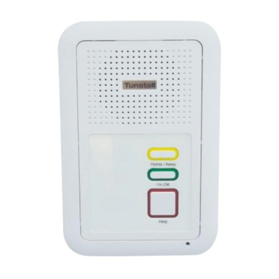
Speech Module What does the speech module look like? The following speech module comes with and without the door entry handset. Below is an image of the speech module. The speech module has an alarm button, I’m OK button and a Home/Away button. The alarm button can be set to be permanently illuminated, this is to help users find the alarm button in the dark. -
Page 13: Door Entry Handset
Door Entry Handset The speech module can have an optional door entry handset for receiving door calls, below is an image of the handset. Each dwelling can have up to five handsets fitted When a door call is received ringing will be heard from the handset and the speech module, lift the handset to have a conversation with the caller. -
Page 14: System Control Panel (Scp)
System Control Panel (SCP) The System Control Panel (SCP) allows the user to place calls to residents, perform simple radio trigger management tasks and to perform certain system configuration tasks. The SCP user interface is menu driven, with illuminated keys indicating available user options. The SCP will have a big button telephone connected to it;... -
Page 15: Change Site Status
Change Site Status This screen enables the user to change the current site status to On Site, Local Offsite (optional) and Off Site. When in On Site mode, an alarm's call group settings are processed as normal. In Off Site all alarms calls are routed to the specified control centre. -
Page 16: Call Menu
Call Menu The call menu allows the user to place a call by either inputting the resident ID or looking the resident up in an alphabetical list. The calls menu also allows broadcast speech (optional). The Quickdial function is not supported. Resident ID Resident Lookup Broadcast... -
Page 17: After A Call
Connected Resident ID: <xxx> <resident name> Clear <mode switch> Figure A.6 After a Call After a call has been finished, the SCP will display details of the next resident ID in the system (as shown in Fig. A.7). To call this resident, press 'Call'. To skip to the next resident in the list, press 'Skip'. To return to the Calls Menu, press 'Exit'. -
Page 18: Trigger Menu
Trigger Menu The Trigger menu allows the user to view, delete and assign triggers to a resident. As in the Call menu, a specific resident can be chosen either by ID ('Resident ID') or by looking up from a list ('Resident Lookup'). -
Page 19: Assigning Triggers
Assigning triggers To assign a trigger to a resident, press the 'Assign' button on the View / Assign screen. The SCP will prompt to activate the trigger with the text shown in (Fig. A.12). Press Radio Trigger Now Figure A.12 When the trigger activation is received by the system, which may take several seconds, the trigger number (The trigger number displayed on the SCP will not match what is printed on the rear of the trigger). -
Page 20: Settings Menu
Settings Menu The settings menu allows the user 4 options: Time Allows the user to enter the time in the format hh:mm Date Allows the user to enter the date in the format dd/mm/yyyy Keypad Sounds Turns the keypad sounds on or off Onsite/OffSite Allows the user to change the site status Time 23:59... -
Page 21: Access Control
Access Control The system may be equipped with the Tunstall fob access system. This allows users who are issued with a fob to gain access through certain doors that are equipped with a reader. The reader is normally mounted within the door panel or next to a warden call panel. - Page 22 Description Group Save Exit Figure A.19 Enter the ID of the fob by using the numeric keypad; only enter the group of 5 digits. Once the ID has been entered, press the OK button. ID : _ _ _ _ _ Clear Exit Figure A.20...
-
Page 23: Deleting A Fob
Once all the details have been entered for the fob, press the Save key. Description Group Save Exit Figure A.23 There is a section in the rear of the manual, where the fob ID, Description and Group can be recorded. Deleting a fob If a fob is no longer needed it is possible to delete this from the system. - Page 24 Once Delete Device has been selected enter the numeric ID of the fob that needs to be deleted using the keypad on the SCP. Delete _ _ _ _ _ Clear Delete Exit Figure A.27 If the fob ID that is entered is recognised by the system, the delete key will become available. This will be indicated by the red LED being illuminated near the word ‘Delete’.
-
Page 25: Advanced Menu
Shutdown This option allows the user to shut down the system; it should only be used when a Tunstall engineer instructs the user to do so. Backup DB Allows the user to back up the system database. The system will confirm successful backup and then will return to the advanced menu screen. -
Page 26: Record Menu
Record Menu This allows the user to customise the system by recording voice tags for resident names, receivers and door panels. The user can also record messages to be left for residents on their speech modules Resident Name Resident Msg Receivers >... -
Page 27: Access Group Log
Access Group Log Group Doors belonging this group... -
Page 28: Access Fob Log
Access Fob Log Fob ID Description Group... - Page 29 Fob ID Description Group...
- Page 30 Fob ID Description Group...
- Page 31 Fob ID Description Group...
- Page 32 Our policy of continual development means that product specification and appearance may change without notice. Tunstall does not accept any responsibility for any errors or omissions contained in this document. © 2014 Tunstall Healthcare Group Ltd. ® TUNSTALL and LIFELINE are registered trademarks.
Need help?
Do you have a question about the ConnectCall and is the answer not in the manual?
Questions and answers