
Related Manuals for Tunstall Lifeline 400


Summary of Contents for Tunstall Lifeline 400
- Page 1 Lifeline 400 user guide q6 18/2/04 10:56 am Page 2 Lifeline 400 installation and user guide Part Number D3707103B...
-
Page 2: Table Of Contents
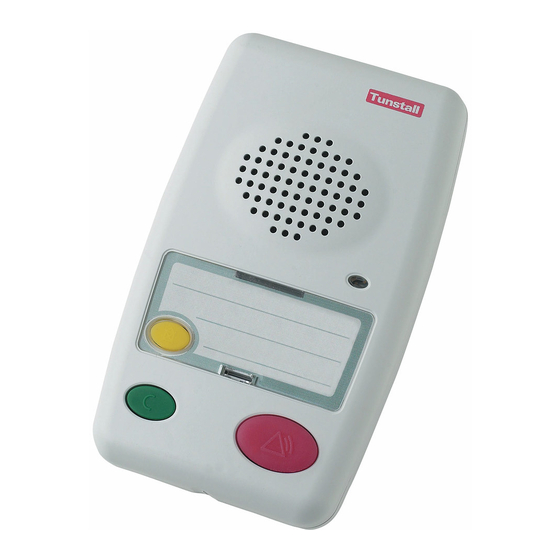
Lifeline 400 user guide q6 18/2/04 10:56 am Page 3 Contents Your Lifeline 400 P3-4 What’s in the box Setting Up The Lifeline 400 P6-7 Installation Advice Peripherals and Sensors Making an Alarm Call P10-11 Cancelling an Alarm Call Personal Radio Triggers... - Page 3 Lifeline 400 user guide q6 18/2/04 10:56 am Page 4 Your Lifeline 400 Speaker Handsfree Illumination LED Away Button (optional) Red Alarm Button Cancel Button...
-
Page 4: Your Lifeline 400
Lifeline 400 user guide q6 18/2/04 10:56 am Page 5 Your Lifeline 400 Telephone Lead Tunstall Accessory Socket (A) Port (G) Ringer on/off Switch Telephone Adaptor Socket (B) Aerial Mains Adaptor Socket (C) Speaker Volume Control (E) Hard Wired Input (F) -
Page 5: What's In The Box
Lifeline 400 user guide q6 18/2/04 10:56 am Page 6 What’s in the box Lifeline 400 Personal Triggers Amie+ Gem+ Mains Adaptor (C) Telephone Adaptor (B) Neck Cord Telephone Lead (A) Belt Clip (Amie+ only) - Page 6 Page 7 Setting Up The L STEP 1 • Plug the telephone lead (A) into the Lifeline 400 (Socket A) and the main telephone wall socket. STEP 2 • Plug the telephone adaptor (B) into the Lifeline 400 (Socket B) and then connect the telephone to the adaptor.
- Page 7 • Adjust speaker volume control (E) by depressing with a pen/pencil. STEP 6 • Connect hard wired peripheral to input (F) (if required). STEP 7 • Make test calls using the alarm button on the Lifeline 400 and each radio/hardwired peripheral.
-
Page 8: Installation Advice
Lifeline 400, via the telephone adaptor (B). USING SMART BOXES/MODEMS Smart box/modem • Always plug the Lifeline 400 directly to the main telephone socket. Equipment such as modems/smart boxes should be connected via the Lifeline 400. -
Page 9: Peripherals And Sensors
10:56 am Page 10 PERIPHERALS AND SENSORS • The Lifeline 400 can be used with an extensive range of peripherals and sensors to provide a comprehensive monitoring solution, tailored to the needs of each individual user. Smoke Detector Fall Detector... -
Page 10: Making An Alarm Call
Lifeline 400 user guide q6 18/2/04 10:57 am Page 11 Making an Alarm Call STEP 1 • To raise an alarm call press the radio trigger or the alarm button on the Lifeline 400. - Page 11 Lifeline 400 user guide q6 18/2/04 10:57 am Page 12 STEP 2 • The user talks to the control centre operator ‘handsfree’ using the powerful speaker and microphone of the Lifeline 400. STEP 3 The control centre • operator summons the...
-
Page 12: Cancelling An Alarm Call
10:57 am Page 13 Cancelling an Alarm Call LIFELINE 400 • To cancel an alarm call made from the Lifeline 400, wait 5 seconds and press the green cancel key. This in-built delay prevents false cancellation of an alarm call. - Page 13 Lifeline 400 user guide q6 18/2/04 10:57 am Page 14 The Amie+ Personal Radio Trigger Neck Cord Water Resistant Visual Call Indicator Typical Range 25-50m Auto Battery Low Belt Clip • The trigger will automatically raise a notification call to the control centre when its battery is low.
-
Page 14: Telephone Line Monitoring P14
(e.g. British Telecom). POWER FAILURE MONITORING • If there is a power failure, the Lifeline 400 will continue to work but its alarm button will flash repeatedly. It will also bleep rapidly 10 times. If the failure lasts more than 1 hour, the unit will automatically dial the control centre. -
Page 15: Away Button P15
You can do this in one of the following three ways depending on how your Lifeline 400 has been set up:- • Lift the handset of your connected telephone and type in the 4 digit PIN number that was given to you when the Lifeline 400 was installed. -
Page 16: Panic Buttons
INTRUDER FUNCTIONALITY AND INACTIVITY MONITORING If your Lifeline 400 has been set up to monitor for inactivity as well as intruders, inactivity moni- toring will automatically be suspended the moment intruder monitoring is armed. When intruder is monitoring is disarmed, inactivity monitoring will automatically be restored. -
Page 17: Help And Advice
• Dust with a soft cloth which can be moistened with a gentle detergent if required. •• PERSONAL RECIPIENTS • Lifeline 400 can be used to make an alarm call to the personal recipient (e.g. a relative) before calling a monitoring centre. Please contact your monitoring centre to enable this facility. -
Page 18: Declaration Of Conformity
DECLARATION OF CONFORMITY We,Tunstall Telecom of Whitley Lodge,Whitley Bridge,Yorkshire, England, DN14 0HR declare that the Lifeline 400 dispersed alarms conform with the essential requirements of the RTTE directive 1999/5/EC. Essential radio test suites have been carried out. Model Numbers: 370ab/xy0... -
Page 19: Wall Mounting
Lifeline 400 user guide q6 18/2/04 10:57 am Page 20 Wall Mounting STEP 1 • Cut out template Template 88mm STEP 2 • Fix to wall and drill holes STEP 3 • Attach screws to wall STEP 5 • Place cables in cable channel for a neat appearance. - Page 20 Our policy of continual development means that product specification and appearance may change without notice. Tunstall Telecom Limited is a member of Tunstall Group Ltd. © 2003 Tunstall Group Ltd. ® TUNSTALL and LIFELINE are registered trade marks of Tunstall Telecom Limited.
Need help?
Do you have a question about the Lifeline 400 and is the answer not in the manual?
Questions and answers