
Related Manuals for Pylontech PowerCube-H1-V2


Summary of Contents for Pylontech PowerCube-H1-V2
- Page 1 Lithium Ion Phosphate Energy Storage System PowerCube-H1/H2-V2 Operation Manual Information Version: V1.0 5PMPA08-00130...
- Page 2 This manual introduces PowerCube-H1/H2-V2 from Pylontech. PowerCube-H1/H2-V2 is a high voltage Lithium-Ion Phosphate Battery storage system. Please read this manual before you install the battery and follow the instruction carefully during the installation process. Any confusion, please contact Pylontech immediately for advice and clarification.
-
Page 3: Table Of Contents
Menu 1. Safety .................................. 1 1.1. Symbol ..................................1 1.2. Reference standards ..............................4 2. System Introduction ............................5 2.1. System description ..............................5 2.2. Specification ................................5 2.3. System Specifications ............................. 6 2.4. Battery Module Specification ..........................7 2.4.1. H48050 ................................ - Page 4 3.6.2. Grounding ..............................24 3.6.3. Internal power and communication cable connection within Rack ........25 3.6.4. Communication wiring connection of the master and slave control modules ....26 3.7. Process of System Turning On .......................... 29 ................................29 3.7.1. Notes 3.7.2.
-
Page 5: Safety
1. Safety The PowerCube-H1/H2-V2 is a high voltage DC system, operated by authorized person only. Read all safety instructions carefully prior to any work and observe them at all times when working on with the system. Incorrect operation or work may cause: Injury or death to the operator or a third party;... - Page 6 Symbol Warning electric shock! in label Symbol Do not place near flammable material in label Symbol Do not reverse connection the positive and negative. in label Symbol Do not place near open flame in label Symbol Do not place at the children and pet touchable area. in label Symbol Recycle label.
- Page 7 Danger: Batteries deliver electric power, resulting in burns or a fire hazard when they are short circuited, or wrongly installed. Danger: Lethal voltages are present in the battery terminals and cables. Severe injuries or death may occur if the cables and terminals are touched. Warning: Do not open or deform the battery module and control module;...
-
Page 8: Reference Standards
1.2. Reference standards Description Code Safety Standard for Secondary IEC62619:2022 Lithium Batteries IEC63056:2020 UN38.3 Safe Transport Standard Recommendations on the ST/SG/AC.10/11/Rev.7/Amend.1/Section 38.3 Transport of Dangerous Goods, Manual of Tests and Criteria EN 300 328 V2.2.2 EN 301 489-1 V2.2.3: EN 301 489-17 V3.2.4; RED Standard EN IEC 61000-6-1:2019 Directive 2014/53/EU... -
Page 9: System Introduction
Pylontech. It can be used to support reliable power for various types of equipments and systems. PowerCube-H1/H2-V2 is especially suitable for those application scenes which required high power output, limited installation space, restricted load-bearing and long cycle life. -
Page 10: System Specifications
2.3. System Specifications PowerCube-H1-48/zzzV PowerCube-H2-48/zzzV Product Type (zzz=240~864,in step of 48) (zzz=240~864,in step of 48) Product Name LFP Lithium Ion Energy Storage System Cell Technology LiFePQ4 System Voltage <1000V Battery System Capacity(kWh) 2.4 × n(where n = 5~18) 3.552 × n (where n = 5~18) Battery System Voltage(Vdc) 48 ×... -
Page 11: Battery Module Specification
2.4. Battery Module Specification 2.4.1. H48050 Product Type H48050 Cell Technology LiFePQ4 Battery Module Capacity(kWh) Battery Module Voltage(Vdc) Battery Module Capacity(AH) Dimension(W*D*H, mm) 442*390*100 Protection Class IP20 Weight(kg) Operation Life(Years) Operation Cycle Life 5,000 ℃ Operation Temperature( 0~50 ℃ Storage Temperature( -20~60 Transportation Certificate UN38.3... -
Page 12: H48074
2.4.2. H48074 Product Type H48074 Cell Technology LiFePQ4 Battery Module Capacity(kWh) 3.552 Battery Module Voltage(Vdc) Battery Module Capacity(AH) Dimension(W*D*H, mm) 442*390*132 Protection Class IP20 Weight(kg) Operation Life(Years) Operation Cycle Life 5,000 ℃ Operation Temperature( 0~50 ℃ Storage Temperature( -20~60 Transportation Certificate UN38.3 8 / 42... -
Page 13: Battery Module Front Interface
2.4.3. Battery Module Front Interface Power Terminal +/- To connect battery series power cables. Status ● ● Status light: to show the battery module’s status (RUN , Alarm and Protection RS232 Terminal Console Communication Terminal: (RJ45 port) follow RS232 protocol, for manufacturer or professional engineer to debug or service. -
Page 14: Control Module Specification
2.5. Control Module Specification Product Type SC1000-100S-V2 Related Product H48050/H48074 Controller Working Voltage 200~1000Vdc System Operation Voltage(Vdc) 200~1000 Charge Current(Max.)(A) Discharge Voltage(Vdc) 200~1000 Discharge Current(Max.)(A) Self-consumption Power(W) Dimension(W*D*H,mm) 442*390*132 Communication Modbus RTU\CAN\LAN Protection Class IP20 Weight(kg) Operation Life(Years) ℃ Operation Temperature( -20~65 ℃... - Page 15 External Power Terminal D+/D- Connect battery system with Power Conversion System. Dry Contact Terminal Dry Contact Terminal: provided 2 input and 4 output dry contact signal. In/out Function Open and close state Internal Using ONLY For wake up signal serial connection using ONLY. For wake up or Always close, when open will switch off the system.
- Page 16 RS232 Console Communication Terminal: (RJ45 port) follow RS232 protocol, for manufacturer or professional engineer to debug or service. Link Port Link Port Communication Terminal: (RJ45 port) for internal communication between multiple serial battery modules and control module. Definition of RJ45 Port Pin RS485 RS232 CANH...
- Page 17 Status and SOC Indicators ● ● Status light: to show the battery module’s status (RUN , Alarm SOC(Battery capacity indicator): 4 green lamps, each light represents 25% capacity. Status and SOC Indicators Instructions STATUS STATUS Protection / (green) (red) Alarm / Battery Status Descriptions ●...
-
Page 18: System Diagram
WIFI Support for the Cloud platform functions. Manufacturer: Pylon Technologies Co., Ltd. Address: Plant 8, No.505 Kunkai Road, JinXi Town, 215324 Kunshan City, Jiangsu Province, PEOPLE'S REPUBLIC OF CHINA Importer: XXXX (Located in installed country) Address: XXXX (Located in installed country) Wireless maximum output power: 20dBm Operating frequency: 2412-2472MHz Gain of antenna: Max 3dBi... - Page 19 15 / 42...
-
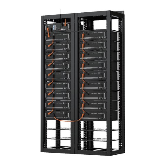
Page 20: Diagram Between Control Module And Battery Modules
2.6.2. Diagram between Control Module and Battery Modules 16 / 42... -
Page 21: Installation
3. Installation Please check every installation step in detail at <Annex 1: Installation and System Turn ON Progress List> during the installation. 3.1. Installation tools The following tools are required to install the battery pack: Wire Cutter Crimping Modular Plier Wire Cutter Screw Driver Set Electric Screw Driver... - Page 22 Torque Requirements Console Communication Terminal: (RJ45 port) follow RS232 protocol, for manufacturer or professional engineer to debug or service. Position Torque(N.m) Picture Module fixation 6.0-7.7 Rack top L-type 30-40 strip (optional) Rack bottom 30-40 fixation Grounding bolts 12-13 18 / 42...
-
Page 23: Working Environments
3.3. Working Environments 3.3.1. Cleaning The battery system has high voltage connectors. The clean condition will cause the isolation characteristic of the system. Before installation and system working must clean the dust and iron scurf to keep the environ- ments cleaning. And the environment must have certain anti-dust ability. The system after long term running must check the humidity and dust cover or not. -
Page 24: Package Items
3.4. Package Items 3.4.1. List of the accessories in the package Item Type Quantity Description Notes Power Cable + (Battery 1pcs/control Orange/0.16m/4AWG/2 Module and Control module Orange Surlok Terminal Module Serial Connection) Power Cable - (Battery 1pcs/control Black/2m/4AWG/2 Module and Control module Black Surlok Terminal Module Serial Connection) -
Page 25: Dc Power Cable
3.4.2. DC Power Cable Power Cable + (Battery Orange/0.16m/4AWG/2 1pcs/control Module and Control Orange Surlok Terminal module Module Serial Connection) Power Cable - (Battery Black/2m/4AWG/2 1pcs/control Module and Control Black Surlok Terminal module Module Serial Connection) 2000 Power Cable (Between Orange/0.18m/4AWG/1 Orange &... -
Page 26: Mechanical And Electrical Installation
3.5. Mechanical and Electrical Installation 3.5.1. Installation Notes Warning: The battery rack is IP00. It must be installed in a restricted access area; Warning: The PowerCube-H1/H2-V2 is high voltage DC system, operated by qualified and authorized person only. 3.5.2. Mechanical Installation of the battery rack If without handling tools must have more than 4 men to handling with it. -
Page 27: Mechanical Installation Of The Battery Module
3.5.3. Mechanical Installation of the battery module Single battery module is 24/32kg. If without handling tools must have more than 1 man to handling with Install the buckle nuts. The position of nuts must meet the position of the battery modules. Install the all battery modules in. -
Page 28: Cable Connection
3.6. Cable Connection 3.6.1. Caution Danger: The battery system is high voltage DC system. Must make sure the grounding of the rack is stable and reliable. Danger: All the plugs and sockets of the power cables must be orange to orange and black to black. -
Page 29: Internal Power And Communication Cable Connection Within Rack
3.6.3. Internal power and communication cable connection within Rack Note: Power cable uses water-proofed connectors. It must keep pressing this Lock Button during pulling out the power plug. 25 / 42... -
Page 30: Communication Wiring Connection Of The Master And Slave Control Modules
3.6.4. Communication wiring connection of the master and slave control modules 3.6.4.1. For single group communication wiring connection to inverter/upper controller The communication cable shall connect follow below diagram. To inverter/upper controller The ADD address shall set follow table, Table of the control module ADD address setting for Single-group Address dial bit CAN Address Master or slave... - Page 31 27 / 42...
- Page 32 The ADD address shall set follow table Table of the control module ADD address setting for Multi-strings Address dial bit CAN Address Master or slave 6(Terminal Resistance) relationship Invalid Master Slave The terminal resistance Slave needs to be activated ON (upward) at the first(master control) and last node(the last slave...
-
Page 33: Process Of System Turning On
3.7. Process of System Turning On 3.7.1. Notes Double check all the power cables and communication cables. Make sure the voltage of the PCS is same level with the battery system. Check all the power switch of every battery system is OFF. - Page 34 · Turn on the “Start Button”: Press and hold the Start Button for more than 5 seconds until the buzzer rings, the LED indicator on front panel will light on if the start-up is successful. 3.7.2.3. Control Module Self-test and Start Process: The battery string’s system will check by itself, if it works normally the battery string system will go to the self-check mode.
- Page 35 3.7.2.4. Black Start If long press the start button 30 seconds AFTER power on. The “STATUS” lamp will become green. When the black start function is enabled, “STATUS” lamp remains red, it means the black start function is failed to active, it needs long press start button again. System will close relay and output for 10mins.
-
Page 36: Process Of System Turning Off
If turned off the “Power Switch” in normal running condition, it must first turn off the PCS. Note After installation, DO NOT forget to register online for full warranty: www.pylontech.com.cn/service/support 32 / 42... -
Page 37: System Debug
4. System Debug This system debug is for BESS system (Battery Energy Storage System). BESS system can’t do the debug itself. It must operation with configured UPS, PCS and EMS system together. Debug Step Content Turn on the BESS system, refer to chapter 3. Before turn on the whole BESS system turn on the load is not allowed! Prepare of debug. -
Page 38: Maintenance
4. If problem remain, contact Pylontech service Other error engineer. 5.1.2. During operation The ‘Failure Definition’ and ‘Failure Mode’ column is reference from Pylontech Modbus protocol Appen- dix IV Error code 1 bit to present. Failure Type Failure Definition Possible Reason Solution 1.Change the RED LED module's... - Page 39 Sensor chip error (Bit8) hardware bypassed module. If not, further bypass the next LED off module and repeat the process. 3. If problem remain, contact Pylontech service engineer. 1. Restart 2. Change the current measurement board Comm. and BMS Internal bus CMU internal error 3.
- Page 40 12m. Restart the system. (Bit17) 3. Reverse sequence connect the comm. cable between the BMSs and change the ADD address settings. Restart the system. 4. Change the BMS CMU or BMS. 5. If problem remain, contact Pylontech service engineer. 36 / 42...
-
Page 41: Replacement Of Main Component Among The Bess
Current IC Error hardware board error (Bit22) 3. Change the CMU or BMS. 4. If problem remain, contact Pylontech service engineer. 1. Check the external power cables of the polarity and connection Pre-charge Pre-charge error. 2. Change the pre-charge circuit board hardware circuit error. -
Page 42: Replacement Of Control Module
5.2.1.4 Dismantle the 4 screws of the battery module’s front face. 5.2.1.5 Handle the battery module out of the rack, and put it to the appoint place. Warning: Single battery module is 24kg/32kg. If without handling tools must more than 1 personnel to handling with it. -
Page 43: Battery Maintenance
5.2.2.3 Dismantle the 4 screws of the battery module’s front face. 5.2.2.4 Install the new control module (BMS). And reconnect all the cables. Refer to chapter 3.5. 5.2.2.5 Turn on this battery string. Refer to chapter 3.6. Caution: Before pull out the communication cables must mark the cable number, to avoid cable wrong sequence. -
Page 44: Output Relay Inspection
5.3.5. Output Relay Inspection [Periodical Maintenance] Under low load condition (low current), control the output relay OFF and ON to hear the relay has click voice, that’s mean this relay can off and on normally. 5.3.6. History Inspection [Periodical Maintenance] Analysis the history record to check has accident (alarm and protection) or not, and analysis its reason. -
Page 45: Shipment
1. The battery modules should meet the UN38.3 certificate standard. 2. In particular, local rules and policy for the product transportation shall be complied with. For more details, please enquiry the Safety Data Sheet (SDS) from Pylontech for more information. Annex 1: Installation and System Turn ON Progress List... -
Page 46: Annex 2: System Turn Off Progress List
Tick after Item Remark completion The first installation should do full charging progress. After Master controller has communicated with each The first slave BMS, it will run parallel operation. It will begin from installation lowest voltage battery string to do the parallel operation should do full during the charging. - Page 48 Pylon Technologies Co., Ltd. No. 73, Lane 887, ZuChongzhi Road, Zhangjiang Hi-Tech Park Pudong, Shanghai 201203, China T+86-21-51317699 | +86-21-51317698 Eservice@pylontech.com.cn Wwww.pylontech.com.cn...
Need help?
Do you have a question about the PowerCube-H1-V2 and is the answer not in the manual?
Questions and answers