
Related Manuals for Pylontech PowerCube-X1-V2


Summary of Contents for Pylontech PowerCube-X1-V2
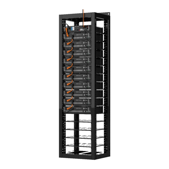
- Page 1 Lithium-Ion Phosphate Energy Storage System PowerCube-X1/X2-V2 Operation Manual Information Version: V1.0 5PMPA08-00129...
- Page 3 This manual introduces PowerCube-X1/X2-V2 from Pylontech. PowerCube- X1/X2-V2 is a high voltage Lithium-Ion Phosphate Battery storage system. Please read this manual before you install the battery and follow the instruction carefully during the installation process. Any confusion, please contact Pylontech immediately for advice and clarification.
-
Page 4: Table Of Contents
Content Safety ..............1 1.1. Symbol ................................... 1 1.2. Reference standards ..........................4 System Introduction ............ 5 2.1. System description ..........................5 2.2. Specification ............................... 6 2.3. System Specifications ......................... 7 2.4. Battery Module Specification ..................... 8 2.4.1. H48050 ....................................8 2.4.2. - Page 5 3.8. Process of System Turning Off ....................35 System Debug ............37 Maintenance ............38 5.1. Trouble Shooting .............................38 5.1.1. Before start up ............................... 38 5.1.2. During operation ..............................38 5.2. Replacement of main component among the BESS ............41 5.2.1. Replacement of Battery module ......................... 41 5.2.2.
-
Page 6: Safety
1. Safety The PowerCube-X1/X2-V2 is a high voltage DC system, operated by authorized person only. Read all safety instructions carefully prior to any work and observe them at all times when working on with the system. Incorrect operation or work may cause: ➢... - Page 7 Symbol Warning electric shock! label Symbol Do not place near flammable material label Symbol Do not reverse connection the positive and negative. label Symbol Do not place near open flame label Symbol Do not place at the children and pet touchable area. label Symbol Recycle label.
- Page 8 Danger: Lethal voltages are present in the battery terminals and cables. Severe injuries or death may occur if the cables and terminals are touched. Warning: Do not open or deform the battery module; Warning: Whenever working on the battery, wear suitable personal protective equipment (PPE) such as rubber gloves, rubber boots and goggles.
-
Page 9: Reference Standards
1.2. Reference standards Description Code Safety Standard IEC62619:2022 Secondary Lithium IEC63056:2020 Batteries UN38.3 Safe Transport Standard Recommendations ST/SG/AC.10/11/Rev.7/Amend.1/Section 38.3 Transport Dangerous Goods, Manual of Tests and Criteria EN 300 328 V2.2.2 EN 301 489-1 V2.2.3: EN 301 489-17 V3.2.4; RED Standard EN IEC 61000-6-1:2019 Directive 2014/53/EU EN IEC 61000-6-2:2019... -
Page 10: System Introduction
PowerCube-X1/X2-V2 is a high voltage battery storage system based on lithium iron phosphate battery, which is one of the new energy storage products developed and produced by Pylontech. It can be used to support reliable power for various types of equipments and systems. -
Page 11: Specification
2.2. Specification... -
Page 12: System Specifications
2.3. System Specifications Product Type PowerCube-X1-V2- PowerCube-X2-V2- 48/zzzV 48/zzzV (zzz=96~480,in step of (zzz=96~480,in step of 48 ) 48 ) Product Name LFP Lithium Ion Energy Storage System Cell Technology LiFePQ4 System Voltage <600V Battery System 2.4 × n 3.552 × n... -
Page 13: Battery Module Specification
Rack 1: 58kg+ 24kg×n (where n = 2~8), 77kg+ 32kg×n (where n Weight(kg) = 2~10) Rack2: 77kg+ 24kg×n (where n = 2~10), 2.4. Battery Module Specification 2.4.1. H48050 Product Type H48050 Cell Technology Li-iron (LFP) Battery Module Capacity (kWh) Battery Module Voltage (Vdc) Battery Module Capacity (AH) Dimension (W*D*H, mm) 442*390*100... -
Page 14: H48074
2.4.2. H48074 Product Type H48074 Cell Technology Li-iron(LFP) Battery Module Capacity(kWh) 3.552 Battery Module Voltage(Vdc) Battery Module Capacity(AH) Dimension(W*D*H, mm) 442*390*132 Protection Class IP20 Weight(kg) Operation Life(Years) Operation Cycle Life 5,000 0~50 Operation Temperature(℃) -20~60 Storage Temperature(℃) Transportation Certificate UN38.3... -
Page 15: Battery Module Front Interface
2.4.3. Battery Module Front Interface Power Terminal +/- To connect battery series power cables. Status Status light: to show the battery module’s status (RUN●, Alarm and Protection●). RS232 Terminal Console Communication Terminal: (RJ45 port) follow RS232 protocol, for manufacturer or professional engineer to debug or service. Link Port 0, 1 Link Port 0, 1 Communication Terminal: for communication between multiple serial battery modules and controller module. -
Page 16: Control Module Specification
2.5. Control Module Specification Product Type SC0500-40S-V2 SC0500-100S-V2 Related Product H48050/H48074 H48050/H48074 Controller Working Voltage 60~600Vdc 60~600Vdc System Operation 60~600 60~600 Voltage(Vdc) Charge Current(Max.)(A) * Discharge Voltage(Vdc) 60~600 60~600 Discharge Current(Max.)(A) Self-consumption Power(W) Dimension(W*D*H,mm) 442*390*87 442*390*132 Communication Modbus RTU\CAN\LAN Modbus RTU\CAN\LAN 10 Protection Class IP20 IP20... - Page 17 Power Terminal B+/B- To connect battery module power cables in series. Power Switch Switch the battery system’s (control module and high voltage DC power) ON/OFF. Caution: When the breaker is tripped off because of over current or short circuit, must wait after 30mins to turn on it again, otherwise may cause the breaker damage.
- Page 18 Black start function: when system turned on and during self- check process, press and hold the start button again for more than 10sec, and relay will close for 10 min. CAN / RS485(Link Port A and B) CAN Communication Terminal: (RJ45 port) follow CAN protocol, for communication between battery system and Power Conversion System.
- Page 19 External 12VDC power supply for the Battery Controller. Status and SOC Indicators Status light: to show the battery module’s status (RUN●, Alarm●). SOC(Battery capacity indicator): green lamps, each light represents 25% capacity. Status and SOC Indicators Instructions STATU STATUS Protection (gree (red) Battery...
-
Page 20: System Diagram
During Power On Device Normal Flash2 Flash2 start-up Success Flash5 BlackStart Black Start Function Fail Flash5 Waiting Flash5 Flash5 Misc/Update(Before Misc Flash2 Forceup) Update Event Event/Update(M2SING) Flash2 Flash2 Update History History/Update(Updating) Flash2 Flash2 Update Info Info/Update(Finished) Flash2 Flash2 Update Note: The flashing instructions, flash 1 - 0.25s light / 3.75s off;... -
Page 21: System Diagram Without Mbms Via Can
2.6.1. System Diagram without MBMS via CAN Multiple battery string parallel connection via CAN communication among BMSs diagram (battery string qty. ≤6 sets). The Battery Controller with ADD address 1 is the master and all remaining Battery Controllers are slave. The external interface is only valid on the Battery Controller with ADD address “1”. -
Page 22: Installation
3. Installation Please check every installation step in detail at <Annex Installation and System Turn ON Progress List> during the install. 3.1. Installation tools The following tools are required to install the battery pack: Wire Cutter Cable Ties Crimping Modular Plier Screw Driver Set Electric Screw Driver Adjustable Wrench... -
Page 23: Safety Gears
with electrical tape. 3.2. Safety Gears It is recommended to wear the following safety gear when dealing with the battery pack. Insulated gloves Safety goggles Safety shoes Torque Requirements Torque(N.m Position Picture Module 6.0-7.7 fixation Rack top L- type strip 30-40 (optional) - Page 24 Rack bottom 30-40 fixation Grounding 12-13 bolts...
-
Page 25: Working Environments
3.3. Working Environments 3.3.1. Cleaning The battery system has high voltage connectors. The clean condition will cause the isolation characteristic of the system. Before installation and system working must clean the dust and iron scurf to keep the environments cleaning. And the environment must have certain anti-dust ability. - Page 26 and reliable. The resistance of the grounding system must be ≤100 mΩ...
-
Page 27: Package Items
3.4. Package Items 3.4.1. List of the accessories in the package Item Type Quantity Description Notes Power Cable + 1pcs/cont Orange/0.16m/4AWG/2 Orange (Battery Module Surlok Terminal and Control module Module Serial Connection) Power Cable - (Battery Module 1pcs/cont Black/2m/4AWG/2 Black and Control Surlok Terminal Module Serial... -
Page 28: Dc Power Cable
A4/A5/A6 3.4.2. DC Power Cable Power Cable + (Battery Module Orange/0.16m/4AWG/2 1pcs/contr and Control Module Serial Orange Surlok Terminal ol module Connection) Power Cable - (Battery Module Black/2m/4AWG/2 Black 1pcs/contr and Control Module Serial Surlok Terminal ol module Connection) 2000 Orange/0.18m/4AWG/1 Power Cable (Between the 1pcs/batte... -
Page 29: Communication Cable
For SC0500-100S-V2 control module: Power Cable/Orange/2m/ External Power Cable + (BMS 1pcs/contr 4AWG/SURLOK Terminal/25-8 'D+' to PCS) ol module ring terminal 2000 Power Cable/Black/2m/ External Power Cable -(BMS 'D- 1pcs/contr 4AWG/SURLOK Terminal/25-8 ' to PCS) ol module ring terminal 2000 3.4.3. -
Page 30: Mechanical And Electrical Installation
3.5. Mechanical and Electrical Installation 3.5.1. Installation Notes Warning: The battery rack is IP00. It must be installed in a restricted access area; Warning: The PowerCube-X1/X2-V2 is high voltage DC system, operated by qualified and authorized person only. 3.5.2. Mechanical Installation of the battery rack. If without handling tools must have more than 4 men to handling with it. -
Page 31: Mechanical Installation Of The Battery Module
3.5.3. Mechanical Installation of the battery module Single battery module is 24/32kg. If without handling tools must have more than 1 man to handling with it. Install the buckle nuts. The position of nuts must meet the position of the battery modules. Install the all battery modules in. -
Page 32: Internal Power And Communication Cable Connection Within Rack
The PowerCube-X1/X2-V2 modules’ grounding is based on metal directly touch between the module’s surface and rack’s surface. So it doesn`t need grounding cables at all. If uses normal rack, it should remove the paint at the corresponding grounding point. Rack Grounding: If there is a grounding metal frame outside the rack, for example, the metal angle steel frame at the bottom of the container, the fix hole of the fix frame can be fixed directly with... -
Page 33: Communication Wiring Connection Of Master And Slave Controller
3.6.4. Communication wiring connection master slave controller 3.6.4.1 single group communication wiring connection inverter/upper controller The communication cable shall connect follow below diagram, To inverter/upper controller The ADD address shall set follow table, Table of the control module ADD address setting for Single- group... - Page 34 Address dial bit Address 6(Terminal Master or slave Resistance) relationship No requirement. Master 3.6.4.2 For Multi-groups communication wiring connection With SC0500-40S-V2 / SC0500-100S-V2, there DONOT need a MBMS for multi-groups operation. For the existing installation (with old SC0500-40S/SC0500-100S) capacity expansion or BMS replacement activity, please REMOVE the MBMS and add on the SC0500-40S-V2 / SC0500-100S-V2 at the master position for further communication with existing inverter directly.
- Page 35 The ADD address shall set follow table, Table of the control module ADD address setting for Multi-groups Address dial bit Address 6(Terminal Master or slave Resistance) relationship Invalid Master The terminal...
- Page 36 resistance needs to be activated ON Slave (upward) at the first(master control) and last node(the last Slave slave control), when multiple controllers are connected in Slave parallel. Slave Slave Slave The ADD of each control module must be set different, setting it to the same will indicate a fault.
-
Page 37: Process Of System Turning On
3.7. Process of System Turning On 3.7.1. Notes Double check all the power cables and communication cables. Make sure the voltage of the PCS is same level with the battery system. Check all the power switch of every battery system is OFF. Warning: The master control module must be turned on after other slave control modules self-check finish. - Page 38 Caution: The time interval between every time switch OFF/ON the “Power Switch” shall >3 minutes. Caution: When the breaker is tripped off because the system has over current or short circuit, must after 30mins to turn on it again, otherwise may cause the breaker damage. ⚫...
- Page 39 Warning: If it has failure during the self-check, must debug the failure then it can start next step. If the “STATUS” lamp shows red from beginning, it means has failure in the battery string, the Power Relays in BMS will switch ON, must debug at first.
-
Page 40: Process Of System Turning Off
Warning: DONOT operate the system restart repeatedly when the Pre-charge error exist. The power connection(D+,D-) may be short circuit. 3.7.2.6. Description of the parallel connection of battery control modules The first installation should do full charging progress. After Master controller has communicated with each slave BMS, it will run parallel operation. - Page 41 If turned off the “Power Switch” in normal running condition, must first turn off the PCS. Note After installation, DO NOT forget to register online for full warranty: www.pylontech.com.cn/service/support...
-
Page 42: System Debug
4. System Debug This system debug is for BESS system (Battery Energy Storage System). BESS system can’t do the debug itself. It must operation with configured UPS, PCS and EMS system together. Debug Step Content Prepare of debug. Turn on the BESS system, refer to chapter 3. Before turn on the whole BESS system turn on the load is not allowed! Remark: Except the BESS, if other equipments... -
Page 43: Maintenance
4. If problem remain, contact Pylontech Other error service engineer. 5.1.2. During operation The ‘Failure Definition’ and ‘Failure Mode’ column is reference from Pylontech Modbus protocol Appendix IV Error code 1 bit to present. Failure Failure Possible Reason Solution... - Page 44 BMS between BMS and battery (Bit2) modules. 2. Restart 3.If problem remain, contact Pylontech service engineer. External DC OV ERR D+ D- voltage Check external inverter's input over extremely higher voltage whether match with the...
- Page 45 If not, further bypass the next LED off module and repeat the process. 3. If problem remain, contact Pylontech service engineer. Comm. CMU internal error 1. Restart Internal or I2C issue 2. Change the current hardware...
-
Page 46: Replacement Of Main Component Among The Bess
3. Reverse sequence connect the comm. cable between the BMSs and change the ADD address settings. Restart the system. 4. Change the BMS CMU or BMS. 5. If problem remain, contact Pylontech service engineer. Failure Failure Possible Reason Solution Type Definition Comm. -
Page 47: Replacement Of Control Module
to chapter 3.8 5.2.1.3 Pull out the Plug of Power Cable +/-. Pull out the plug of communication cable. Danger: the power cables and plugs still have high voltage DC power from serial connected battery modules (battery module can’t be turned off), must be careful to handle the Power plugs. -
Page 48: Replacement Of Mbms
5.2.2.2 Pull out the plugs of Power Cables and the communication plugs. Danger: the power cables still have high voltage DC power from another battery module, must be careful to handle the Power plugs. 5.2.2.3 Dismantle the 4 screws of the battery module’s front face. 5.2.2.4 Install the new control module (BMS). -
Page 49: Battery Maintenance
5.2.3.2 Dismantle the 4 screws. 5.2.3.3 Install the new MBMS inside. And reconnect the cables. Refer to chapter 3.5. 5.2.3.4 Turn on this MBMS. Refer to chapter 3.6. Caution: Before pull out the communication cables must mark the cable number, to avoid cable wrong sequence. 5.3. -
Page 50: Recycle
Some system function must be maintenance during the EMS restart, it is recommended to maintenance the system every 6 months. 5.3.8. Recycle Note Damaged batteries may leak electrolyte or produce flammable gas. In case a damaged battery needs recycling, it shall follow the local recycling regulation (i.e. -
Page 51: Capacity Expansion
1. The battery modules should meet the UN38.3 certificate standard. particular, local rules policy product transportation shall be complied with. For more details, please enquiry the Safety Data Sheet (SDS) from Pylontech for more... - Page 52 information.
-
Page 53: Annex 1: Installation And System Turn On Progress List
Annex 1: Installation and System Turn ON Progress List Tick after Item Remark completio environment meeting technical requirements. 3.3.1 Cleaning ☐ Refer 3.3.2 Temperature chapter 3.3 3.3.3 Radiating System 3.3.4 Heating System 3.3.5 Grounding System ☐ Battery rack is installed follow the technical Refer requirements. -
Page 54: Annex 2: System Turn Off Progress List
operation. It will begin from lowest voltage charging battery string to do the parallel operation progress. during the charging. If the status LED of BMS turns to green, it means this battery string parallel operation. If the system need black start, ☐... - Page 57 Pylon Technologies Co., Ltd. No. 73, Lane 887, ZuChongzhi Road, Zhangjiang Hi-Tech Park Pudong, Shanghai 201203, China T+86-21-51317699 | +86-21-51317698 service@pylontech.com.cn www.pylontech.com.cn...
Need help?
Do you have a question about the PowerCube-X1-V2 and is the answer not in the manual?
Questions and answers