Table of Contents
Advertisement
Quick Links
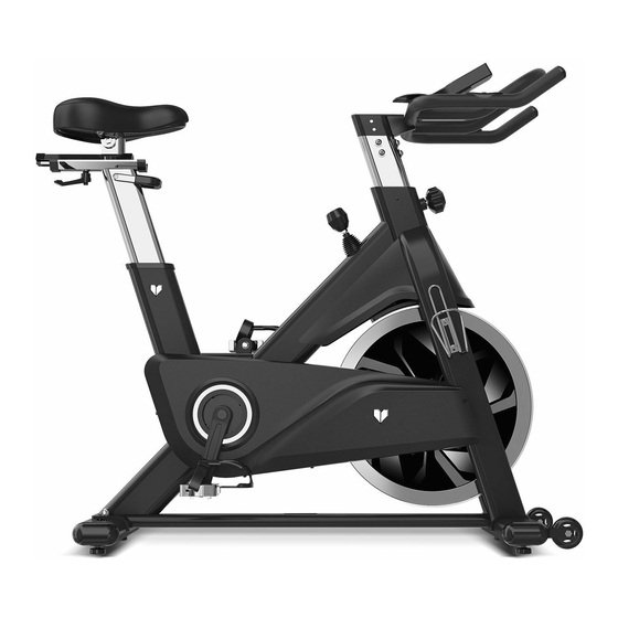
SM-800 Spin Bike
Read all instructions carefully before using this product.
Retain this owner's manual for future reference.
IMPORTANT
All nuts and bolts are to be checked and tightened on a regular basis. This includes pedals and
other moving parts. Failure to do so may cause damage to your threads and void your warranty.
NOTE:
Product may vary slightly from the item pictured due to model upgrades. This manual may be subject to updates or changes.
Up to date manuals are available through our website at www.lifespanfitness.com.au
USER MANUAL
Advertisement
Table of Contents

Related Manuals for LifeSpan SM-800


Summary of Contents for LifeSpan SM-800
- Page 1 SM-800 Spin Bike USER MANUAL Read all instructions carefully before using this product. Retain this owner’s manual for future reference. IMPORTANT All nuts and bolts are to be checked and tightened on a regular basis. This includes pedals and other moving parts. Failure to do so may cause damage to your threads and void your warranty.
-
Page 2: Table Of Contents
TABLE OF CONTENTS Important Safety Instructions ....... 03 II. Care Instructions ..........04 III. -
Page 3: Important Safety Instructions
I. IMPORTANT SAFETY INSTRUCTIONS WARNING: Read all instructions before using this machine. It is important your machine receives regular maintenance to prolong its useful life. Failing to regularly maintain your machine may void your warranty. Please always keep this manual with you. •... -
Page 4: Care Instructions
• Always keep this instruction manual and assembly tools at hand for reference. • The equipment is not suitable for therapeutic use. • The pulse or heart rate sensors are not medical devices. Various factors, including the user’s movement, may affect the accuracy of heart rate readings. The pulse sensors are intended only as exercise aids in determining heart rate trends in general. -
Page 5: Exploded Diagram
III. EXPLODED DIAGRAM EXPLODED DIAGRAM |... -
Page 6: Parts List
IV. PARTS LIST Name Spec. Quantity Unit Tube Plug 100*50*2 φ52*43, M8X25 Stopper Carriage Bolt GB/T 12-1988 M8X62 Rear Stabilizer Weldment Flat Washer 1 GB/T 95-2002 8 Domed Nut 1 GB/T 802-1988 M8 Hex Head Bolt 1 GB/T 5780-2000 M8*40 Bearing 1 608ZZ φ69X26... - Page 7 Name Spec. Quantity Unit φ28*6.5 Crank Plug Hex Flange Surface Nut 2 M12X1.25 Pedal JD-304V M20*1.5 Left Crank 170*42.5 Right Crank 170*42.5 Outer Chain Cover 756*283*71 Screw 1 GB/845-85 ST4.2X9.5 Screw 2 GB/T 15856.1-2002 ST4.2X16 Belt Bolt 2 GB/T 70.3-2000 M8*18 φ25*182 Alex φ200*24...
- Page 8 Name Spec. Quantity Unit Nylon Nut GB/T 889.1-2000 M5 Aluminum Handle 80*16*10 Spanner 6# (86X35) Crosshead Spanner S=13,14,15 Ф5*56 Long Shaft Ф8*50.5 Step Shaft Ф8*Ф5.2*20 Spacer Ф8*16 Fixed Shaft Ф5*23 Short Shaft Aluminum Buckle 32*26*15 Fixing Frame 65*27.5*23.5 Upper Cover 115*56*12.5 Front Bushing 257*48*46...
-
Page 9: Assembly Instructions
V. ASSEMBLY INSTRUCTIONS STEP 1 STEP 2 Assemble Front and Rear Stabilizers Assemble Seat 1. Attached the Front Stabilizer (pt.11) to the 1. Fix the Seat on the Seat Post, then lock the Main Frame (pt.21), Lock the Front 2pcs of nut under the Seat firmly. Stabilizer on the Main frame with 2pcs of Carriage Bolts (pt.3) and 2pcs of Flat Washers (pt.5) and 2pcs of Domed Nut... - Page 10 5 52 52 5 Convex point ATTENTION: Connected with the computer line, to Gap(A1) corresponding to the Convex Point (A2) to insert link. STEP 3 Assemble Handlebar/Computer 1. Fix the Handlebar (pt.20) on the Handlebar Post (pt.19) with 6pcs of Bolt (pt.10) and 6pcs of Washer (pt.52) and 6pcs of Flat Washer (pt.5).
- Page 11 STEP 4 Assemble Pedals/Bottle Holder 1. Take the Left Pedal (pt.42L) the one with a L Sticker, screw its axle Counter-clockwise into the Left Crank. 2. Take the Right Pedal (pt.42R) the one with a R sticker, screw its axle Clockwise into the Right Crank. IMPORTANT: Ensure both pedals are fully tighten as using pedals while loose can damage your thread and affect your warranty.
- Page 12 FIG A FIG B A. Adjusting the Tension: B. Using the Emergency Brake Function: Increasing or decreasing the tension allows The same knob that allows you to adjust the you to add variety to your workout sessions tension of the bike also doubles as the by adjusting the resistance level of the bike.
-
Page 13: Seat And Handlebar Adjustment
VI. SEAT AND HANDLEBAR ADJUSTMENT SEAT ADJUSTMENT UP/DOWN To adjust the seat height, hold onto the seat and pull the seat post up to your desired height. To lower it you will need to pull the release lever underneath the seat up and while holding the lever, push the seat down, then release the lever to lock into position. -
Page 14: Computer Operation
VII. COMPUTER OPERATION DISPLAY OPERATIONS Item Description Displays the current workout duration. TIME Measuring range: 0:00 to 99:59 Displays the user’s workout speed. SPEED Measuring range: 0.0 to 99.9 Displays the user’s workout distance. DISTANCE Measuring range: 0.0 to 99.9 Displays the user’s approximate calories burnt during workout. - Page 15 OPERATION PROCEDURE Powering On the Machine The monitor requires 4x AA batteries to function. Once the batteries are installed, hold RESET for 2 seconds to power on the monitor. The monitor will buzz for 1 second to confirm. Once powered on, the LCD will display all functions for 2 seconds and then display the wheel diameter and units for 1 second.
- Page 16 Workout Mode Selection Use the control wheel to select a workout mode: Choose quick start or set a specific goal for the workout, such as: 1. Target Time 2. Target Distance 3. Target Calories 4. Target Heart Rate 5. Target Watt 6.
- Page 17 Target Distance 1. Use the control wheel to set Target DISTANCE (Preset value = 5.0), press START/STOP to begin workout in Target Distance mode. 2. DISTANCE begins to count down from Target value, TIME, CALORIES, RPM, SPEED, WATT, HEART RATE will be displayed accordingly.
- Page 18 Target Watt 1. Use the control wheel to set the Target WATT (preset value = 100), press START/STOP to begin workout in Target Watt mode. 2. TIME begins to count up, DISTANCE, CALORIES, RPM, SPEED, WATT, HEART RATE will be displayed accordingly.
- Page 19 Watt Program 1. Use control wheel to select: Beginner, Advanced or Sporty and press MODE to confirm. 2. Use control wheel to set Time (preset value = 30:00), press START/STOP to begin workout in Watt Program mode. 3. TIME begins to count down from Target value, DISTANCE, CALORIES, RPM, SPEED, WATT, HEART RATE will be displayed accordingly.
-
Page 20: Exercise Guide
VIII. EXERCISE GUIDE PLEASE NOTE: Before beginning any exercise program, consult your physician. This is important especially if you are over the age of 45 or individuals with pre-existing health problems. The pulse sensors are not medical devices. Various factors, including the user’s movement, may affect the accuracy of heart rate readings. - Page 21 COOL DOWN Finish each workout with a light jog or walk for at least 1 minute. Then complete 5 to 10 minutes of stretching to cool down. This will increase the flexibility of your muscles and will help prevent post- exercise problems.
-
Page 22: Warranty
Any claim against this warranty must be made through your original place of purchase. Proof of purchase is required before a warranty claim may be processed. If you have purchased this product from the Official Lifespan Fitness website, please visit https://lifespanfitness.com.au/warranty-form For support outside of warranty, if you wish to purchase replacement parts or request a repair or service, please visit https://lifespanfitness.com.au/warranty-form and fill in our Repair/Service... -
Page 23: Hand Pulse Technology
X. HAND PULSE TECHNOLOGY This product comes equipped with hand pulse sensors which are used to pick up tiny EKG/ECG signals that run through the body when your heart beats. These electrical EKG/ECG signals are very small and must be amplified 1000 times to make the signal viable for the computer to display your pulse. To ensure proper operation: •... - Page 24 WWW.L IF ESPAN F ITNE S S . COM . A U...
Need help?
Do you have a question about the SM-800 and is the answer not in the manual?
Questions and answers