Table of Contents
Advertisement
Quick Links
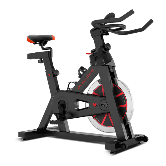
SM-310 M2 Spin Bike
USER MANUAL
Read all instructions carefully before using this product.
Retain this owner's manual for future reference.
IMPORTANT
All nuts and bolts are to be checked and tightened on a regular basis. This includes pedals and
other moving parts. Failure to do so may cause damage to your threads and void your warranty.
NOTE:
This manual should not be used to guide your purchasing decision. Your product, and the contents inside its carton, may vary
from what is listed in this manual. This manual may also be subject to updates or changes. Updated manuals are available
through our website at
www.lifespanfitness.com.au
Advertisement
Table of Contents

Related Manuals for LifeSpan SM-310 M2


Summary of Contents for LifeSpan SM-310 M2
- Page 1 SM-310 M2 Spin Bike USER MANUAL Read all instructions carefully before using this product. Retain this owner’s manual for future reference. IMPORTANT All nuts and bolts are to be checked and tightened on a regular basis. This includes pedals and other moving parts.
-
Page 2: Table Of Contents
TABLE OF CONTENTS Important Safety Instructions ....... 03 II. Care Instructions ..........04 III. -
Page 3: Important Safety Instructions
I. IMPORTANT SAFETY INSTRUCTIONS WARNING: Read all instructions before using this machine. It is important your machine receives regular maintenance to prolong its useful life. Failing to regularly maintain your machine may void your warranty. Please always keep this manual with you. •... -
Page 4: Care Instructions
• The pulse or heart rate sensors are not medical devices. Various factors, including the user’s movement, may affect the accuracy of heart rate readings. The pulse sensors are intended only as exercise aids in determining heart rate trends in general. II. -
Page 5: Exploded Diagram
III. EXPLODED DIAGRAM 14 15 EXPLODED DIAGRAM |... -
Page 6: Parts List
IV. PARTS LIST Name Quantity Specifications PEDAL JD-301(9/16") END CAP1 INNER60*30*1.5 CARRIAGE BOLT M8*42 REAR STABILIZER WELDING FLAT WASHER GB/T 95-2002 8 DOMED NUT GB/T 802-1988 M8 (H=16mm) SPRING ADJUSTMENT KNOB φ57*62 (M16*1.5) PLASTIC SLEEVE 53.5*23.5*1.5 LOCK NUT M33*1*4 VERTICAL SEAT POST WELDING END CAP2 53.5*23.5*1.5... - Page 7 Name Quantity Specifications FIXING NUT 1 GB/T 6177.2-2000 M10*1.25 CRANK END CAP φ23*7.5 SHEET IRON δ5 LOCK NUT GB/T 889.1-2000 M8 CHAIN WEEL A7K-16 1/2"*1/8" 16T(1.37") LEFT CRANK 170*43 CRANK COVER φ45*28 BEARING 6203ZZ DOMED NUT GB/T 802-1988 M6 U BRACKET δ2.5 FIXING NUT 2 GB/T 6177.2-2000 M10*1.0...
- Page 8 Name Quantity Specifications GB/T 41-2000 M8 FIXING NUT 2 GB/T 6173-2000 M10*1.0 (H=5.0mm) FIXING TUBE φ13.6*φ10.3*35 BEARING 6000ZZ FLYWHEEL φ453*27 (13KG) FLYWHEEL SHAFT φ10*147 WOOLLY BLOCK 85*40*6 FIXED SEAT φ28 COMPUTER HS-6065 FIXING NUT φ28*M20*1 FLYWHEEL COVER φ59*35 SCREW 4 ST2.9*9.5 LEFT PROTECT COVER 157*73*157...
-
Page 9: Assembly Instructions
V. ASSEMBLY INSTRUCTIONS PREPARATION 1. Before assembling make sure that you will have enough space around the item. 2. Use the present tooling for assembling. 3. Before assembling please check whether all needed parts are available (at the above of this instruction sheet you will find an explosion drawing with all single parts (marked with numbers) which this item consists of. - Page 10 STEP 2 1. Slide the Vertical Seat Post (pt.10) into the seat post housing on the Main Frame (pt.16). You will have to slacken the knurled section of the Knob (pt.7) and pull the knob back and then select the desired height. Release the knob and retighten the knurled portion. Then slide the Seat Post (pt.12) into the Vertical Seat Post (pt.10), use the knob (pt.7) to tighten.
- Page 11 Convex Point ATTENTION: Connected with the computer line, to Gap (A1) corresponding to the convex point (A2) to insert link. STEP 3 1. Slide the Handlebar Post (pt.17) into the handlebar post housing on the main frame. You will have to slacken the knurled section of the Knob (pt.7) and pull the knob back and then select the desired height.
- Page 12 STEP 4 1. The Pedals (pt.1L & pt.1R) are marked "L" and "R" - Left and Right. Connect them to their appropriate crank arms. The right crank arm is on the right - hand side of the cycle as you sit on it. Important Note: that the Right pedal should be threaded on clockwise and the Left pedal anticlockwise.
- Page 13 1. Adjusting the Tension Increasing or decreasing the tension allows you to add variety to your workout sessions by adjusting the resistance level of the bike. To increase tension and increase resistance (requiring more strength to pedal), turn the Tension Control Knob (pt.25) to the right.
-
Page 14: Seat And Handlebar Adjustment
VI. SEAT AND HANDLEBAR ADJUSTMENT Seat Adjustment To adjust the seat height, slacken the spring knob on the vertical post stem on the main frame and pull back the knob. Position the vertical seat post for the desired height so that holes are aligned, then release the knob and retighten it. -
Page 15: Exercise Guide
VII. EXERCISE GUIDE Using your SPINNING BIKE provides you with several benefits, it will improve your physical fitness, tone muscle and in conjunction with calorie controlled diet help you lose weight. THE WARM UP PHASE This stage helps get the blood flowing around the body and the muscles working properly. It will also reduce the risk of cramp and muscle injury. - Page 16 MUSCLE TONING To tone muscle while on your SPINNING BIKE you will need to have the resistance set quite high. This will put more strain on our leg muscles and may mean you cannot train for as long as you would like. If you are also trying to improve your fitness you need to alter your training program.
-
Page 17: Exercise Computer Instruction Manual
VIII. EXERCISE COMPUTER INSTRUCTION MANUAL OVERVIEW: The unit is an electronic that display all workout parameters on LCD display. The workout parameters include: Odometer (If have), Time, Speed, Distance, Calories and Pulse (If have). All workout parameters may be selected by the select key. MODE OR FUNCTION ACTION If push the button, the unit will be on and display the parameters of the last... -
Page 18: Warranty
Any claim against this warranty must be made through your original place of purchase. Proof of purchase is required before a warranty claim may be processed. If you have purchased this product from the Official Lifespan Fitness website, please visit https://lifespanfitness.com.au/warranty-form For support outside of warranty, if you wish to purchase replacement parts or request a repair or service, please visit https://lifespanfitness.com.au/warranty-form and fill in our Repair/Service... -
Page 19: Hand Pulse Technology
X. HAND PULSE TECHNOLOGY This product comes equipped with hand pulse sensors which are used to pick up tiny EKG/ECG signals that run through the body when your heart beats. These electrical EKG/ECG signals are very small and that they must be amplified 1000 times to make the signal useful for the computer to display your pulse. - Page 20 WWW.L IFES PA N FI TN E S S . C OM .A U...
Need help?
Do you have a question about the SM-310 M2 and is the answer not in the manual?
Questions and answers