Table of Contents
Advertisement
Quick Links
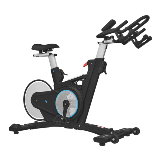
SM-900 Commercial
Product may vary slightly from the item pictured due to model upgrades.
Read all instructions carefully before using this product.
Retain this owner's manual for future reference.
NOTE:
This manual should not be used to guide your purchasing decision. Your product, and the contents inside its carton, may vary
from what is listed in this manual. This manual may also be subject to updates or changes. Updated manuals are available
through our website at
www.lifespanfitness.com.au
Spin Bike
USER MANUAL
Advertisement
Table of Contents

Related Manuals for LifeSpan SM-900


Summary of Contents for LifeSpan SM-900
- Page 1 SM-900 Commercial Spin Bike USER MANUAL Product may vary slightly from the item pictured due to model upgrades. Read all instructions carefully before using this product. Retain this owner’s manual for future reference. NOTE: This manual should not be used to guide your purchasing decision. Your product, and the contents inside its carton, may vary from what is listed in this manual.
-
Page 2: Table Of Contents
TABLE OF CONTENTS Important Safety Instructions ....... 03 II. Care Instructions ..........04 III. -
Page 3: Important Safety Instructions
I. IMPORTANT SAFETY INSTRUCTIONS WARNING: Read all instructions before using this machine. It is important your machine receives regular maintenance to prolong its useful life. Failing to regularly maintain your machine may void your warranty. Please always keep this manual with you. •... -
Page 4: Care Instructions
• Always keep this instruction manual and assembly tools at hand for reference. • The equipment is not suitable for therapeutic use. • The pulse or heart rate sensors are not medical devices. Various factors, including the user’s movement, may affect the accuracy of heart rate readings. The pulse sensors are intended only as exercise aids in determining heart rate trends in general. -
Page 5: Exploded Diagram
III. EXPLODED DIAGRAM 10 20 11 44 11 40R EXPLODED DIAGRAM |... -
Page 6: Parts List
IV. PARTS LIST Description Description Main Frame Hex Bolt M10x50 Handlebar Post Nylon Nut M10 Steel Ring Arch Washer D10xΦ25x2 Front Stabilizer 27L/R Cranks 1 pr. 28L/R Front Foot Rest Rear Stabilizer 1 pr. Saddle Post Rear Foot Rest Handlebar Joint Adjusting Foot Pad Upper Saddle Glider Rear Post Bushing... - Page 7 Description Description Display Cross Pan Head Screw Computer Bracket Power Adapter Cross Pan Head Screw M6x8 NOTE: Most of the listed assembly hardware has been packaged separately, but some hardware items have been preinstalled in the identified assembly parts. In these instances, simply remove and reinstall the hardware as assembly is required.
-
Page 8: Assembly Instructions
V. ASSEMBLY INSTRUCTIONS STEP 1 1. Take off Packing Tube (46) from Main Frame (1), keep well the Packing Tube (46) in case of packing next time. 2. Install the Front Stabilizer (4) and Rear Stabilizer (5) to Main Frame (1) by using: - Inner pan head screw M10x25 (19) - Flat Washer D10xΦ20x2 (22) - Spring Washer D10 (21) - Page 9 STEP 2 Secure the Pedals (40L/R) to Cranks (27L/R). Tighten the Left pedal (40L) Counterclockwise, and tighten the Right pedal (40R) Clockwise. Make sure the Pedals (40L/R) are locked tightly during exercise according to the direction indicated by the arrow in the following figure, otherwise the thread of pedals will be damaged. STEP 3 1.
- Page 10 STEP 4 1. Lock the Upper handlebar glider (9) to Handlebar Joint (7) with Inner Hex Bolt M8x15 (45). 2. Take the Locking Screw (13) and thread it over the Handlebar Joint (7). Insert the bottom of Upper handlebar glider (9) to the Locking Screw (13) with Pressure Spring (43) and T-shape Nut (14). 3.
- Page 11 STEP 5 1. Lock the Locking Handlebar Joint (36) to Handlebar Joint (7) with Inner Hex Bolt M6x10 (17), and then cover Screw Cap (37). NOTE: Make sure the Handlebar Joint (7) is locked tightly before exercise. 2. Lock the Lower glider cap (33) to the Lower glider of Handlebar post (2) tightly with Cross pan head screw M4x10 (12).
- Page 12 STEP 6 1. Connect extension wire (42) through the middle hole of Computer bracket (48) to the line of display (47), and then lock the display (47) to Computer bracket (48) with Cross pan head screw (50). 2. Lock Computer bracket (48) to Handlebar Joint (7) with Cross pan head screw M6x8 (49). 3.
-
Page 13: Operation Guide
VI. OPERATION GUIDE Specifications Showing your current speed. Range: 0.0~99.9 KM/ Speed KM/H(M/H) H(M/H). Showing the current rotate per minute. Range : 0~999. The accumulative exercise time, range : 0:00~99M59S. the preset time range is 5:00~99M00S. The computer will start to count down from preset time to 0:00 with TIME average time for each resistance level. - Page 14 FUNCTION 1. Program: 20 programs as following: A: 1 Manual Program P01 (Fig1) B: 10 Preset Program Profile (Fig2~Fig11): P02: ROLLING P03: VALLEY P04: FATBURN P05: RAMP P06: MOUNTAIN P07: INTERVAL P08: CARDIO P09:ENDURANCE P10: SLOPE P11: RALLY Fig 1 Fig 2 Fig 3 Fig 4...
- Page 15 Fig 13 Fig 14 Fig 15 Fig 16 E. 4 User Setting Programs: P17~P20 (Fig17~Fig20) Fig 17 Fig 18 Fig 19 Fig 20 2. Record the user’s data of AGE even cut off the power. 3. Display Speed , RPM , TIME, DIST., CAL., WATT, PULSE, LEVEL at the same time. 4.
- Page 16 2. START/STOP: • Press START/STOP button to start or stop the programs. • During any mode, hold down this button for 2 seconds to totally reset the computer. 3. UP: • In stop mode and, press MODE button to select the program or set parameters. If the related window value flash, press this button to increase the value.
- Page 17 B. Press MODE to confirm the selected watt control program, and enter into time setting window. C. The time will flash, and then press UP/DOWN button to set up the desired time. Press MODE to confirm the value. D. The distance will flash, and then press UP/DOWN to set up the desired distance value. Press MODE to confirm the value.
- Page 18 NOTE: During exercise, the user’s heart rate value depends on resistance level and speed. The heart rate control program is to ensure your heart rate within the preset value. When the computer detect your current heart rate is higher than preset, it will decrease the resistance level automatically or you may slow down exercise.
-
Page 19: Exercise Guide
VII. EXERCISE GUIDE PLEASE NOTE: Before beginning any exercise program, consult your physician. This is important especially if you are over the age of 45 or individuals with pre-existing health problems. The pulse sensors are not medical devices. Various factors, including the user’s movement, may affect the accuracy of heart rate readings. - Page 20 COOL DOWN Finish each workout with a light jog or walk for at least 1 minute. Then complete 5 to 10 minutes of stretching to cool down. This will increase the flexibility of your muscles and will help prevent post- exercise problems.
-
Page 21: Warranty
Any claim against this warranty must be made through your original place of purchase. Proof of purchase is required before a warranty claim may be processed. If you have purchased this product from the Official Lifespan Fitness website, please visit https://lifespanfitness.com.au/warranty-form For support outside of warranty, if you wish to purchase replacement parts or request a repair or service, please visit https://lifespanfitness.com.au/warranty-form and fill in our Repair/Service... -
Page 22: Hand Pulse Technology
IX. HAND PULSE TECHNOLOGY This product comes equipped with hand pulse sensors which are used to pick up tiny EKG/ECG signals that run through the body when your heart beats. These electrical EKG/ECG signals are very small and must be amplified 1000 times to make the signal viable for the computer to display your pulse. To ensure proper operation: •... - Page 24 WWW.LIFESPA NF ITN ES S.COM.AU...
Need help?
Do you have a question about the SM-900 and is the answer not in the manual?
Questions and answers