Table of Contents
Advertisement
Quick Links
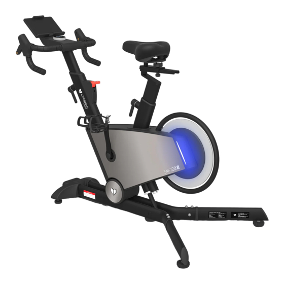
SM-720I Incline/Decline Spin Exercise
Bike with Automatic Magnetic Resistance
Product may vary slightly from the item pictured due to model upgrades.
Read all instructions carefully before using this product.
Retain this owner's manual for future reference.
NOTE:
This manual should not be used to guide your purchasing decision. Your product, and the contents inside its carton, may vary
from what is listed in this manual. This manual may also be subject to updates or changes. Updated manuals are available
through our website at
USER MANUAL
www.lifespanfitness.com.au
Find the
Digital Manual
Online
Advertisement
Table of Contents

Related Manuals for LifeSpan SM-720I


Summary of Contents for LifeSpan SM-720I
- Page 1 SM-720I Incline/Decline Spin Exercise Bike with Automatic Magnetic Resistance USER MANUAL Find the Digital Manual Online Product may vary slightly from the item pictured due to model upgrades. Read all instructions carefully before using this product. Retain this owner’s manual for future reference.
-
Page 2: Table Of Contents
TABLE OF CONTENTS Important Safety Instructions ....... 03 II. Care Instructions ..........05 III. -
Page 3: Important Safety Instructions
I. IMPORTANT SAFETY INSTRUCTIONS Basic precautions, including the following important safety instructions should always be followed when using this spinning bike. Read all instructions before using this spin bike. To reduce the risk of electric shock, always unplug the spin bike from the electrical outlet immediately after using and before cleaning, assembling, or servicing the spin bike. - Page 4 • Always wear suitable sports shoes. The use of shoes with heels, leather soles or running shoes with spikes is prohibited. • CAUTION: Always make sure that your arms and legs as well as (small) children, pets or other objects are not close to the rear flywheel during operation to avoid possible serious injuries or damage to the device.
-
Page 5: Care Instructions
II. CARE INSTRUCTIONS IMPORTANT a. All nuts and bolts are to be checked and tightened on a regular basis. This includes pedals and other moving parts. Failure to do so may cause damage to your threads and void your warranty. b. -
Page 6: Parts List
III. PARTS LIST HARDWARE PACKAGE: MTB110A-BC001 (B17) S5 x 1pc. (B18) S13-15 x 1pc. (D24) Ø6 (D22) Ø8 (D16) ST3.5*10 x 2pcs. x 4pcs. x 11pcs. (D26) Ø8 x 11pcs. (D10) M8*15 x 8pcs. (D12) M6*12 x 4pcs. (D07) M8*55 x 2pcs. (D28) M8*35 x 1pc. -
Page 7: Assembly Instructions
IV. ASSEMBLY INSTRUCTIONS D10 D26 D22 D10 M8*15 x 8pcs. B17 S5 x 1pc D26 D22 D28 M8*35 x 1pc. D07 M8*55 x 2pcs. STEP 1: 1. Use an Allen wrench (B17) with 3-in-1 screws (D07*2) and 3-in-1 screws (D28*1) to fix the front foot pad fixing plate group (B) to the main frame assembly (A) and lock it tightly. - Page 8 D16 ST3.5*10 x 2pcs. B17 S5 x 1pc. STEP 2: 1. First, fasten the buckle (H) on the IPAD holder group (E) into the square hole (K) on the electronic watch group (F). Then install the IPAD holder group (E) on the electronic watch group (F) with the cross wrench (B17) and the cross-pan head self-tapping screw (D16).
- Page 9 D08 M5*10 x 1pc. D12 D24 D12 M6*12 x 4pcs. B18 S13-15 x 1pc. B17 S5 x 1pc. STEP 3: 1. Fasten the upper segment line (E09) and lower segment line (E10) as shown in the figure. Then use the hex wrench (B17) 2-in-1 screw (D12*4) to fix the electronic meter group (F) to the instrument tube group (A02) and lock it tightly.
- Page 10 STEP 4: 1. Place the seat pack (G) on the seat pack tube (A03) and use a twist (C21), and square neck bolt (D02) to secure the seat pack (G) and tighten bolt. | ASSEMBLY INSTRUCTIONS...
- Page 11 STEP 5: 1. Move the stationary bike to the position with power supply, ensure that there is a space distance of 0.6 meters around, and then plug the power adapter (E17) into the power interface (E14) as shown in the figure. CAUTION: When powering on the bike it will automatically swing back and forth to calibrate the slope! ASSEMBLY INSTRUCTIONS |...
-
Page 12: Adjustment Instructions
V. ADJUSTMENT INSTRUCTIONS SEAT HEIGHT 1. To adjust the height of tube group (A02)/seat cushion tube group (A03), first loosen the L-shaped elastic pin assembly (B12) by rotating it counterclockwise, and then rotate it clockwise to lock it. When operating, face the L-shaped elastic pin assembly (B12) to distinguish the direction. 2. - Page 13 FLOOR LEVELERS 1. When the machine shakes due to uneven floor, adjust the adjustable foot mat (C29) counterclockwise or clockwise until they touch the ground evenly. ADJUSTMENT INSTRUCTIONS |...
-
Page 14: Emergency Brake Use
VI. EMERGENCY BRAKE USE Press the brake button down to make an emergency brake. | EMERGENCY BRAKE USE... -
Page 15: How To Move The Machine
VII. HOW TO MOVE THE MACHINE Using two hands hold the left and right rear foot tube and lift the machine about 45 degrees angle, so that the front two moving wheels on the ground. You can only push the machine forward or pull back. HOW TO MOVE THE MACHINE |... -
Page 16: Computer Operation
VIII. COMPUTER OPERATION WINDOW AND BUTTON DESCRIPTION 1. LED window displays the following fuctions: LED window multiplexed display, in the running state 5 seconds in turn switch display, operation knob, priority display resistance gear, operation slope, priority display slope. A. Time Window: Displays time. Time range from 0:00-99:59, after 99:59 is reached the time will reset to 00:00. - Page 17 C. Knob Clockwise Rotation: During operation, turning clockwise will increase resistance. In the standby state, it can also be used to select the built-in program P1-P2-P3. D. Knob Counterclockwise Rotation: During operation, turning counterclockwise will decrease resistance. In the standby state, it can also be used to select the built-in program P1-P2-P3. E.
- Page 18 Shutdown: The system can be turned off at any time by turning off the power switch without damaging the system. Note: 1. Check that your equipment is receiving power before use. 2. If there is any problem with the machine or power cable, please contact the place of purchase. Slope Motor Calibration In the standby state, hold down the external incline plus or minus key for 3 seconds at the same time, and the system will enter the automatic incline calibration.
-
Page 19: Exercise Guide
IX. EXERCISE GUIDE PLEASE NOTE: Before beginning any exercise program, consult your physician. This is important especially if you are over the age of 45 or individuals with pre-existing health problems. The pulse sensors are not medical devices. Various factors, including the user’s movement, may affect the accuracy of heart rate readings. - Page 20 COOL DOWN Finish each workout with a light jog or walk for at least 1 minute. Then complete 5 to 10 minutes of stretching to cool down. This will increase the flexibility of your muscles and will help prevent post- exercise problems.
-
Page 21: Warranty
Any claim against this warranty must be made through your original place of purchase. Proof of purchase is required before a warranty claim may be processed. If you have purchased this product from the Official Lifespan Fitness website, please visit https://lifespanfitness.com.au/warranty-form For support outside of warranty, if you wish to purchase replacement parts or request a repair or service, please visit https://lifespanfitness.com.au/warranty-form and fill in our Repair/Service... - Page 24 WWW.LIFESPA NF ITN ES S.COM.AU...
Need help?
Do you have a question about the SM-720I and is the answer not in the manual?
Questions and answers