Table of Contents
Advertisement
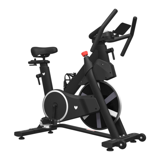
SM-420 Spin Bike with Automatic
Magnetic Resistance
Product may vary slightly from the item pictured due to model upgrades.
Read all instructions carefully before using this product.
Retain this owner's manual for future reference.
NOTE:
This manual should not be used to guide your purchasing decision. Your product, and the contents inside its carton, may vary
from what is listed in this manual. This manual may also be subject to updates or changes. Updated manuals are available
through our website at
USER MANUAL
www.lifespanfitness.com.au
Advertisement
Table of Contents

Related Manuals for LifeSpan SM-420


Summary of Contents for LifeSpan SM-420
- Page 1 SM-420 Spin Bike with Automatic Magnetic Resistance USER MANUAL Product may vary slightly from the item pictured due to model upgrades. Read all instructions carefully before using this product. Retain this owner’s manual for future reference. NOTE: This manual should not be used to guide your purchasing decision. Your product, and the contents inside its carton, may vary from what is listed in this manual.
-
Page 2: Table Of Contents
TABLE OF CONTENTS Important Safety Instructions ....... 03 II. Care Instructions ..........04 III. -
Page 3: Important Safety Instructions
I. IMPORTANT SAFETY INSTRUCTIONS WARNING: Read all instructions before using this machine. It is important your machine receives regular maintenance to prolong its useful life. Failing to regularly maintain your machine may void your warranty. Please always keep this manual with you. •... -
Page 4: Care Instructions
• Always keep this instruction manual and assembly tools at hand for reference. • The equipment is not suitable for therapeutic use. • The pulse or heart rate sensors are not medical devices. Various factors, including the user’s movement, may affect the accuracy of heart rate readings. The pulse sensors are intended only as exercise aids in determining heart rate trends in general. -
Page 5: Exploded Diagram
III. EXPLODED DIAGRAM EXPLODED DIAGRAM |... -
Page 6: Parts List
IV. PARTS LIST Description Description Seat cushion Front foot tube assembly Front and rear adjustment support Right pedal Cushion adjusting knob Handrail adjusting pipe Seat cushion adjusting pipe Handrail assembly assembly IP Assembly Main frame assembly External power adapter Left foot pedal Rear foot tube assembly PARTS PACKAGE TOOLS &... - Page 7 Item Description L-shaped adjusting handle is short Flat washer Length of L-shaped adjusting handle INSTALLATION TOOLS 5mm 13 17mm, 19mm 13mm, 14mm, 15mm PARTS LIST |...
-
Page 8: Assembly Instructions
V. ASSEMBLY INSTRUCTIONS Some parts may be pre-fitted to the equipment. TOOLS STEP 1 1. Remove the hexagon flat head screw, standard spring washer and flat washer on the packing foot tube with a 5 # hexagon wrench. 2. Discard the removed packing foot tube, internal hexagon flat round head screw, standard spring washer and flat washer. - Page 9 STEP 2 1. Use scissors to cut the knot tied to the limit board, and then remove the two boards fixed to the frame assembly (5). 2. The four fixing wood blocks (H) sandwiched on both sides of the flywheel should also be removed. TOOLS STEP 3 1.
- Page 10 TOOLS FIG A IMPORTANT: Before tightening make sure the pedal shaft and crank are perpendicular when assembling (Fig. B). The Right pedal should be threaded on clockwise and the Left pedal anticlockwise and the nut going in opposite directions to the pedals. Ensure to fully tighten both pedals as loose pedals will cause damage to the thread and this will affect your warranty.
- Page 11 TOOLS STEP 5 1. Loosen the guide wire and use the guide wire to pass the wiring head through the armrest adjustment assembly (10), as shown in Figure A. 2. Loosen the L-shaped adjustable handle at the front by turning anti-clockwise and pulling up handle as shown on image.
- Page 12 TOOLS STEP 6 1. Remove the guide wire on the armrest adjusting assembly (10), and then connect the connector wire on the armrest adjusting assembly (11) with the connector wire on the armrest adjusting assembly (10), as shown in Figure A. 2.
- Page 13 STEP 7 1. Connect the power adapter at the bottom rear of the spin bike frame. Use the equipment according to the operation instructions. CAUTION: Turn the brake handle counter-clockwise to the bottom before plugging in, leaving the brake handle in a non-clasping state. ASSEMBLY INSTRUCTIONS |...
- Page 14 TRANSPORTATION WHEELS 1. When moving the machine, grab the front end of the handle and push it down, so that the rollers on the foot tube are completely in contact with the ground, then start moving the machine to your desired location.
- Page 15 SEAT ADJUSTMENT Seat Height Adjustment: Rotate the L-shaped adjustable handle counterclockwise with one hand, hold the seat cushion with the other hand, then pull it up (or push it down) to adjust to the desired position. Then turn the L-shaped adjustable handle clockwise to tighten. Seat Fore/Backward Adjustment: Release the seat cushion adjustment knob, slide the seat cushion back and forth, adjust to the desired position, and then tighten the knob.
- Page 16 HANDLEBAR ADJUSTMENT Handlebar Height Adjustment: Rotate the L-shaped adjustable handle counterclockwise with one hand, grab the armrest with the other hand and pull it up (or push it down) to adjust to the desired position. Then turn the L-shaped adjustable handle clockwise to tighten. | ASSEMBLY INSTRUCTIONS...
-
Page 17: Operation Guide
VI. OPERATION GUIDE 1.1 DESCRIPTION IS DISPLAYED Item No. Items Display Window Brief Instructions 1. Outer ring shows 24 effect lights 2. Displays Level (resistance); Resistance values Full View from 1-16. 3. Displays Speed, Time, Distance (km/hr) and Calories. 4. Displays Bluetooth connectivity. 1. - Page 18 Item No. Items Display Window Brief Instructions Rotation: During motion state, turn the dial clockwise for more resistance and anti-clockwise for less resistance. A sound is generated when rotating. 1.3 DISPLAY OPERATIONS FIG 1 FIG 2 FIG 3 FIG 4 Ready State 1.
- Page 19 FIG 5 FIG 6 FIG 7 FIG 8 FIG 9 FIG 10 FIG 11 FIG 12 Scan Mode 3. The numbers in the main window are rotated by default when the scan icon is lit up. Speed, Time, Distance and Calories will switch every 3 seconds (Fig. 5-8). 4.
- Page 20 1.4 DATA DISPLAY DESCRIPTION Item No. Items Display Window Brief Instructions Resistance Resistance levels 1-16. Higher gear is more resistance. Levels When Scan is lit up, the display will scan through the Scan other Data. When not lit up it will be locked on the selected display mode.
-
Page 21: Exercise Guide
VII. EXERCISE GUIDE PLEASE NOTE: Before beginning any exercise program, consult your physician. This is important especially if you are over the age of 45 or individuals with pre-existing health problems. The pulse sensors are not medical devices. Various factors, including the user’s movement, may affect the accuracy of heart rate readings. - Page 22 COOL DOWN Finish each workout with a light jog or walk for at least 1 minute. Then complete 5 to 10 minutes of stretching to cool down. This will increase the flexibility of your muscles and will help prevent post- exercise problems.
-
Page 23: Warranty
Any claim against this warranty must be made through your original place of purchase. Proof of purchase is required before a warranty claim may be processed. If you have purchased this product from the Official Lifespan Fitness website, please visit https://lifespanfitness.com.au/warranty-form For support outside of warranty, if you wish to purchase replacement parts or request a repair or service, please visit https://lifespanfitness.com.au/warranty-form and fill in our Repair/Service... -
Page 24: Hand Pulse Technology
IX. HAND PULSE TECHNOLOGY This product comes equipped with hand pulse sensors which are used to pick up tiny EKG/ECG signals that run through the body when your heart beats. These electrical EKG/ECG signals are very small and must be amplified 1000 times to make the signal viable for the computer to display your pulse. To ensure proper operation: •... - Page 28 WWW.LIFESPA NF ITN ES S.COM.AU...
Need help?
Do you have a question about the SM-420 and is the answer not in the manual?
Questions and answers