Table of Contents
Advertisement
Quick Links
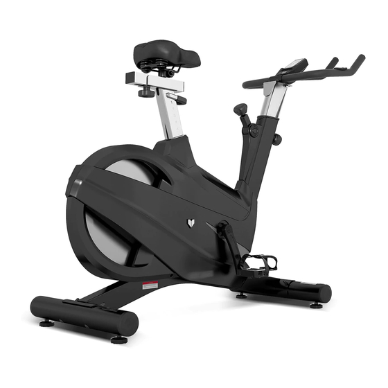
SM-700
Spin Bike
USER MANUAL
Read all instructions carefully before using this product.
Retain this owner's manual for future reference.
IMPORTANT
All nuts and bolts are to be checked and tightened on a regular basis. This includes pedals and
other moving parts. Failure to do so may cause damage to your threads and void your warranty.
NOTE:
Product may vary slightly from the item pictured due to model upgrades. This manual may be subject to updates or changes.
Up to date manuals are available through our website at www.lifespanfitness.com.au
Advertisement
Table of Contents

Subscribe to Our Youtube Channel
Related Manuals for LifeSpan SM-700


Summary of Contents for LifeSpan SM-700
- Page 1 SM-700 Spin Bike USER MANUAL Read all instructions carefully before using this product. Retain this owner’s manual for future reference. IMPORTANT All nuts and bolts are to be checked and tightened on a regular basis. This includes pedals and other moving parts. Failure to do so may cause damage to your threads and void your warranty.
-
Page 3: Table Of Contents
TABLE OF CONTENTS Important Safety Instructions ....... 04 Care Instructions ..........05 III. -
Page 4: Important Safety Instructions
I. IMPORTANT SAFETY INSTRUCTIONS WARNING: Read all instructions before using this machine. It is important your machine receives regular maintenance to prolong its useful life. Failing to regularly maintain your machine may void your warranty. Please always keep this manual with you. •... -
Page 5: Care Instructions
• The pulse or heart rate sensors are not medical devices. Various factors, including the user’s movement, may affect the accuracy of heart rate readings. The pulse sensors are intended only as exercise aids in determining heart rate trends in general. II. -
Page 6: Exploded Diagram
III. EXPLODED DIAGRAM | EXPLODED DIAGRAM... -
Page 7: Parts List
IV. PARTS LIST Name Quantity Specifications Main Frame Weldment Belt Wheel Holder Weldment Seat Slider Weldment Handlebar Post Weldment Saddle Aq -6010 1185 * Φ1 .2 Resistance Line Belt Δ2.5 Metal Plate Bolt1 M6*16 10L/R Pedal Jd -301( 9/16") 11L/R Crank L/R 170*27 Sensor... - Page 8 Name Quantity Specifications Plastic Sleeve 70*30*1.5 Vertical Seat Post Weldment Seat Tube Pront Bushing 260*38.3*36.5 Seat Tube Rear Bushing 300*56.1*36.5 Φ 8.5*Φ 5.5*17 Silicon Tube 1 Sensor Holder Ltf8163 Bolt1 M6*35 Bolt M8*10 Bolt M8*15 Flat Washer 1 Flat Washer 3 Bolt1 M8*15 Flat Washer...
- Page 9 Name Quantity Specifications Bearing 608Z 6001Zz Φ12*142 Short Flywheel Shaft Φ 16*Φ 12.1*49.1 Casing Pipe Φ430*Φ58*Φ28 Flywheel Φ14*14 Plastic Plug Φ56*28 Crank Protective Cover Screw St 4 .2 * 1 9 St2.9*9.5 16 .8 * Φ 10*T 6 Brake Spacer Computer St-7607 Pulse Line...
- Page 10 Name Quantity Specifications Magnetic 6001Zz Φ12*142 Bolt2 Φ 16*Φ 12.1*49.1 Middle Axle Φ430*Φ58*Φ28 Belt Pulley Φ14*14 Sensor Wire Φ56*28 Pulley Bolt1 St2.9*9.5 16 .8 * Φ 10*T 6 Stepped Shaft Long Shaft St-7607 Aluminum Handle L=700 Gloves Weldment Φ58*33 Washer Aluminum Clasp 38*38*1.5 Aluminum Bracket...
-
Page 11: Assembly Instructions
V. ASSEMBLY INSTRUCTIONS PREPARATION 1. Before assembling make sure that you will have enough space around the item. 2. Use the present tooling for assembling. 3. Before assembling please check whether all needed parts are available (at the above of this instruction sheet you will find an explosion drawing with all single parts (marked with numbers) which this item consists of. - Page 12 STEP 2 1. The Saddle post is pre-assembled in the main frame. Fix the Saddle (pt.5) on the Seat post (pt.3) as shown | ASSEMBLY INSTRUCTIONS...
- Page 13 Convex Point ATTENTION: Connected with the computer line, to Gap (A1) corresponding to the convex point (A2) to insert link. STEP 3 1. Insert the Handlebar Post (pt.4) into the handlebar post tube of the main frame. You will have to slacken the Knob (pt.73) and pull the knob back.
- Page 14 STEP 4 1. The Pedals (pt.10L & pt.10R) are marked "L" and "R" - Left and Right. Connect them to their appropriate crank arms. The right crank arm is on the right- hand side of the cycle as you sit on it. Important Note: The Right pedal should be threaded on clockwise and the Left pedal anticlockwise.
- Page 15 ADJUSTING THE TENSION 1. Adjust the Resistance To increase resistance (requiring more strength to pedal), turn the Resistance Control Knob (pt.75) to the right. To decrease resistance (requiring less strength to pedal), turn the Resistance Control Knob (pt.75) to the left. 2.
-
Page 16: Seat And Handlebar Adjustment
VI. SEAT AND HANDLEBAR ADJUSTMENT Seat Adjustment To adjust the seat height, slacken the spring knob on the vertical post stem on the main frame and pull back the knob. Position the vertical seat post for the desired height so that holes are aligned, then release the knob and retighten it. -
Page 17: Computer Operation
VII. COMPUTER OPERATION BUTTONS MODE To confirm all settings. To set up the value of TIME, DISTANCE, CALORIES and PULSE. You can hold the button to increase the value fast. (The computer has to be in stop condition). To clear the set-up value. Press RESET key and hold for 2 seconds to reset all function RESET figures. - Page 18 Drawing A Drawing B 2. Get access to the set-up mode of TIME/DISTANCE/CALORIES/PULSE. When you are in each set-up mode, for example in the time set-up mode: time value is blinking, you can press "SET" button to adjust the value and press "MODE" for confirmation. The set-up of DISTANCE, CALORIES &...
- Page 19 6. Recovery: a. When the user presses "RECOVERY" button, the RECOVERY function is active. At this time only PULSE and TIME is working, other functions will not be displayed, and the Sensor Input is not available. TIME starts to count down from "0:60", Pulse signal will be blinking according user’s heart rate BPM.
-
Page 20: Exercise Guide
VIII. EXERCISE GUIDE PLEASE NOTE: Before beginning any exercise program, consult your physician. This is important especially if you are over the age of 45 or individuals with pre-existing health problems. The pulse sensors are not medical devices. Various factors, including the user’s movement, may affect the accuracy of heart rate readings. - Page 21 COOL DOWN Finish each workout with a light jog or walk for at least 1 minute. Then complete 5 to 10 minutes of stretching to cool down. This will increase the flexibility of your muscles and will help prevent post- exercise problems.
-
Page 22: Warranty
Any claim against this warranty must be made through your original place of purchase. Proof of purchase is required before a warranty claim may be processed. If you have purchased this product from the Official Lifespan Fitness website, please visit https://lifespanfitness.com.au/warranty-form For support outside of warranty, if you wish to purchase replacement parts or request a repair or service, please visit https://lifespanfitness.com.au/warranty-form and fill in our Repair/Service... -
Page 23: Hand Pulse Technology
X. HAND PULSE TECHNOLOGY This product comes equipped with hand pulse sensors which are used to pick up tiny EKG/ECG signals that run through the body when your heart beats. These electrical EKG/ECG signals are very small and that they must be amplified 1000 times to make the signal useful for the computer to display your pulse. - Page 24 WWW.L IF ESPAN F ITNE S S . COM . A U...
Need help?
Do you have a question about the SM-700 and is the answer not in the manual?
Questions and answers