Advertisement
Quick Links
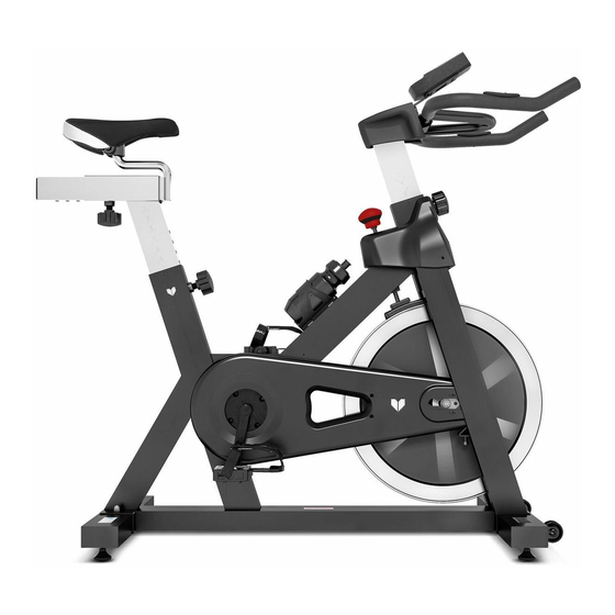
SM-410 Spin Bike
Read all instructions carefully before using this product.
Retain this owner's manual for future reference.
IMPORTANT
All nuts and bolts are to be checked and tightened on a regular basis. This includes pedals and
other moving parts. Failure to do so may cause damage to your threads and void your warranty.
NOTE:
Product may vary slightly from the item pictured due to model upgrades. This manual may be subject to updates or changes.
Up to date manuals are available through our website at www.lifespanfitness.com.au
USER MANUAL
Advertisement

Related Manuals for LifeSpan SM-410


Summary of Contents for LifeSpan SM-410
- Page 1 SM-410 Spin Bike USER MANUAL Read all instructions carefully before using this product. Retain this owner’s manual for future reference. IMPORTANT All nuts and bolts are to be checked and tightened on a regular basis. This includes pedals and other moving parts. Failure to do so may cause damage to your threads and void your warranty.
-
Page 2: Table Of Contents
TABLE OF CONTENTS Important Safety Instructions ....... 03 II. Care Instructions ..........04 III. -
Page 3: Important Safety Instructions
I. IMPORTANT SAFETY INSTRUCTIONS WARNING: Read all instructions before using this machine. It is important your machine receives regular maintenance to prolong its useful life. Failing to regularly maintain your machine may void your warranty. Please always keep this manual with you. •... -
Page 4: Care Instructions
• Always keep this instruction manual and assembly tools at hand for reference. • The equipment is not suitable for therapeutic use. • The pulse or heart rate sensors are not medical devices. Various factors, including the user’s movement, may affect the accuracy of heart rate readings. The pulse sensors are intended only as exercise aids in determining heart rate trends in general. -
Page 5: Exploded Diagram
III. EXPLODED DIAGRAM EXPLODED DIAGRAM |... -
Page 6: Parts List
IV. PARTS LIST Name Quantity Specifications Main Frame Weldment Plastic Sleeve Material:pp Plastic Sleeve Material:pp Φ14*14 Plastic Plug Φ23*7.5 Plastic Plug Hex Flange Nut M10*1.25 Decorative Cover 736*70*292 Belt 5Pk 53In Pedal Jd-301(9/16") R Pedal Jd-301(9/16") L Right Crank 170*27 Bolt M8*18 Φ20*158... - Page 7 Name Quantity Specifications Brake Knob M10*100 Plastic Sleeve Pa66 Screw St2.9*9.5 Φ15.5*Φ1.5x15 Spring Square Nut 20*20*T8(M10) Lock Nut Brake Lever Weldment Φ2.0*52 Spring Square Plastic Block 20.6*20.6*16 Handlebar Post Weldment Decorative Cover 115*89*75 Screw St4.2x19 Handlebar Weldment Bolt M8*15 Computer Bracket Weldment Computer St-7607...
- Page 8 Name Quantity Specifications Bolt M8*40 Hex Flange Nut M12x1.25 Bolt M8*10 Δ2.5 Metal Plate Pinch Roller Holder Weldment Φ43*Φ34*24 Wheel Ф14*Ф6*T2.5 Flat Washer Bolt M6*12 Φ16*Φ12*156 Core Shaft Bearing 6001Zz Flywheel 18Kg Hexagon Nut M12x1.25 H=7 Supporting Frame Weldment Φ18*Φ10*10 Plastic Sleeve Magnet Holder Weldment...
-
Page 9: Assembly Instructions
V. ASSEMBLY INSTRUCTIONS NOTE! Before assembly ensure there is enough space around the item. Check and count all parts are present. Note: Some nuts and bolts may be already attached to the machine. TOOLS STEP 1 1. Lock the Front Stabilizer (pt.51) to the Main Frame (pt.1) with two sets of Ø8 Flat Washer (pt.56), M8 Domed Nut (pt.57) and M8*42 Carriage Bolt (pt.55). - Page 10 STEP 2 1. Insert the Vertical Seat Post (pt.23) into the seat post tube of the Main Frame. You will have to slacken the Knob (pt.24) and pull the knob back. Then select the desired height. Release the knob and retighten the knob. 2.
- Page 11 Convex Point ATTENTION: Connected with the computer line, to Gap (A1) corresponding to the convex point (A2) to insert link. STEP 3 1. Insert the Handlebar Post (pt.37) into the handlebar post tube of the main frame. You will have to slacken the Knob (pt.24) and pull the knob back.
- Page 12 STEP 4 1. The Pedals (pt.9L & pt.9R) are marked "L" and "R" - Left and Right. Connect them to their appropriate crank arms. The right crank arm is on the right- hand side of the cycle as you sit on it. Important Note: that the Right pedal should be threaded on clockwise and the Left pedal anticlockwise.
- Page 13 ADJUSTING THE TENSION 1. Adjust the Resistance To increase resistance (requiring more strength to pedal), turn the Resistance Control Knob (pt.28) to the right. To decrease resistance (requiring less strength to pedal), turn the Resistance Control Knob (pt.28) to the left. 2.
-
Page 14: Computer Operation
VI. COMPUTER OPERATION BUTTONS MODE To confirm all settings. To set up the value of TIME, DISTANCE, CALORIES and PULSE. You can hold the button to increase the value fast. (The computer has to be in stop condition). To clear the set-up value. Press RESET key and hold for 2 seconds to reset all function RESET figures. - Page 15 Drawing A Drawing B 2. Get access to the set-up mode of TIME/DISTANCE/CALORIES/PULSE. When you are in each set-up mode, for example in the time set-up mode: time value is blinking, you can press "SET" button to adjust the value and press "MODE" for confirmation. The set-up of DISTANCE, CALORIES &...
- Page 16 6. Recovery: a. When the user presses "RECOVERY" button, the RECOVERY function is active. At this time only PULSE and TIME is working, other functions will not be displayed, and the Sensor Input is not available. TIME starts to count down from "0:60", Pulse signal will be blinking according user’s heart rate BPM.
-
Page 17: Exercise Guide
VII. EXERCISE GUIDE PLEASE NOTE: Before beginning any exercise program, consult your physician. This is important especially if you are over the age of 45 or individuals with pre-existing health problems. The pulse sensors are not medical devices. Various factors, including the user’s movement, may affect the accuracy of heart rate readings. - Page 18 COOL DOWN Finish each workout with a light jog or walk for at least 1 minute. Then complete 5 to 10 minutes of stretching to cool down. This will increase the flexibility of your muscles and will help prevent post- exercise problems.
-
Page 19: Warranty
VIII. WARRANTY AUSTRALIAN CONSUMER LAW Many of our products come with a guarantee or warranty from the manufacturer. In addition, they come with guarantees that cannot be excluded under the Australian Consumer Law. You are entitled to a replacement or refund for a major failure and compensation for any other reasonably foreseeable loss or damage. - Page 20 WWW.L IF ESPAN F ITNE S S . COM . A U...
Need help?
Do you have a question about the SM-410 and is the answer not in the manual?
Questions and answers