Table of Contents
Advertisement
Quick Links
A l l t e s t I n s t r u me n t s , I n c .
5 0 0 C e n t r a l A v e .
F a r mi n g d a l e , N J 0 7 7 2 7
P : ( 7 3 2 ) 9 1 9 - 3 3 3 9
F : ( 7 3 2 ) 9 1 9 - 3 3 3 2
a l l t e s t . n e t
s s a l e s @ a l l t e s t . n e t
T h e t e s t & me a s u r e me n t
e q u i p me n t y o u n e e d a t
t h e p r i c e y o u w a n t .
A l l t e s t c a r r i e s t h e w o r l d ' s l a r g e s t s e l e c t i o n o f
u s e d / r e f u r b i s h e d b e n c h t o p t e s t & me a s u r e me n t
e q u i p me n t a t 5 0 % t h e p r i c e o f n e w .
O O u r e q u i p me n t i s g u a r a n t e e d w o r k i n g , w a r r a n t i e d , a n d
a v a i l a b l e w i t h c e r t i f i e d c a l i b r a t i o n f r o m o u r i n - h o u s e s t a f f
o f t e c h n i c i a n s a n d e n g i n e e r s .
• 1 0 + f u l l t i me t e c h n i c i a n s w i t h o v e r 1 5 0 y e a r s o f
s p e c i a l i z a t i o n
• 9 0 d a y w a r r a n t y & 5 d a y r i g h t o f r e t u r n o n a l l
e q u i p me n t
• • 1 - 3 y e a r w a r r a n t i e s f o r n e w a n d
p r e mi u m- r e f u r b i s h e d e q u i p me n t
• E v e r y u n i t t e s t e d t o O E M s p e c i f i c a t i o n s
• S a t i s f a c t i o n g u a r a n t e e d
Y o u h a v e p l a n s , w e w i l l h e l p y o u a c h i e v e t h e m.
A n y p r o j e c t . A n y b u d g e t .
t
G e t a q u o t e t o d a y !
C C a l l ( 7 3 2 ) 9 1 9 - 3 3 3 9 o r e ma i l s a l e s @a l l t e s t . n e t .
Advertisement
Table of Contents
Troubleshooting

Related Manuals for Agilent Technologies 8511B


Summary of Contents for Agilent Technologies 8511B
- Page 1 T h e t e s t & me a s u r e me n t e q u i p me n t y o u n e e d a t t h e p r i c e y o u w a n t . A l l t e s t I n s t r u me n t s , I n c .
- Page 2 Agilent Technologies 8511B Frequency Converter Test Set Operating and Service Manual Agilent Part Number: 08511-90073 Printed in USA November 2001 Supersedes November 1999...
-
Page 3: Notice
The information contained in this document is subject to change without notice. Agilent Technologies makes no warranty of any kind with regard to this material, including, but not limited to, the implied warranties of merchantability and fitness for a particular purpose. Agilent shall not be liable for errors contained herein or for incidental or consequential damages in connection with the furnishing, performance, or use of this material. -
Page 4: What You'll Find In This Manual
Chapter 2 Specifications • Chapter 3 Installation • Chapter 4 Operations • Chapter 5 Performance Tests • Chapter 6 Test Set Troubleshooting • Chapter 7 Replacement Procedures • Chapter 8 Replaceable Parts Agilent 8511B Test Set Operating and Service Manual iii... -
Page 5: Warranty
NO OTHER WARRANTY IS EXPRESSED OR IMPLIED. AGILENT SPECIFICALLY DISCLAIMS THE IMPLIED WARRANTIES OR MERCHANTABILITY AND FITNESS FOR A PARTICULAR PURPOSE. iv Agilent 8511B Test Set Operating and Service Manual... -
Page 6: Assistance
Product maintenance agreements and other customer assistance agreements are available for Agilent products. For assistance, call your local Agilent Sales and Service Office (refer to “Service and Support” on page vi). Agilent 8511B Test Set Operating and Service Manual v... -
Page 7: Service And Support
1 800 16510170 (fax) (632) 8426809 (fax) ( PLDT subscriber only) 1 800 16510288 Taiwan People’s Republic of China (tel) 0800-047-866 (tel) (preferred): 800-810-0189 (fax) (886) 2 25456723 (tel) (alternate): 10800-650-0021 (fax) 10800-650-0121 vi Agilent 8511B Test Set Operating and Service Manual... -
Page 8: Safety And Regulatory Information
Class A product (CISPER 11, Clause 4). This symbol indicates that the power line switch is ON. This symbol indicates that the power line switch is OFF or in STANDBY position. Agilent 8511B Test Set Operating and Service Manual vii... -
Page 9: Safety Earth Ground
If this product is to be powered by autotransformer, make sure the common terminal is connected to the neutral (grounded) side of the ac power supply. viii Agilent 8511B Test Set Operating and Service Manual... - Page 10 73/23/EEC and the EMC Directive 89/336/EEC and carry the CE-marking accordingly. Santa Rosa, CA, USA 2 September 2000 Greg Pfeiffer/Quality Engineering Manager For further information, please contact your local Agilent Technologies sales office, agent or distributor Agilent 8511B Test Set Operating and Service Manual ix...
-
Page 11: Typeface Conventions
Edit Parameters • Used for menus, lists, dialog boxes, and button boxes on a computer monitor from which you make selections using the mouse or keyboard: Double-click to quit the program. EXIT x Agilent 8511B Test Set Operating and Service Manual... -
Page 12: Table Of Contents
Figure 1-1. 8511B Test Set with Accessories Supplied ... 1-2 Verifying the Agilent 8511B ........1-3 Measurement Accuracy . - Page 13 Introduction ..........2-1 Table 2-1. 8510/8511B Specifications ..... . . 2-1 Table 2-2.
- Page 14 If the Self-Test Fails to Run ....... . 6-9 Agilent 8511B Test Set Operating and Service Manual Contents-3...
- Page 15 Replaceable Parts Lists ........8-9 Table 8-1. Agilent 8511B Replaceable Parts ....8-9 Figure 8-7.
-
Page 16: General Information
General Information Introduction This manual for the Agilent 8511B frequency converter test set is used in conjunction with the Agilent 8510 network analyzer manual set. These manuals provide the information needed to properly configure your system and make measurements. NOTE The 8511B manual may be inserted into the 8510 test sets and accessories binder that was provided with your 8510 manual set. - Page 17 General Information Figure 1-1 8511B Test Set with Accessories Supplied 1-2 Agilent 8511B Test Set Operating and Service Manual...
-
Page 18: Verifying The Agilent 8511B
General Information Verifying the Agilent 8511B Verifying the Agilent 8511B The Agilent 8511B has been designed to operate specifically with the 8510 network analyzer. • To install the instrument, turn to Chapter 3, “Installation”. • To verify that the instrument meets its published specifications, use the Agilent 8511A,B and Antenna Measurement System Performance Verification Software (part number 08511-60024). -
Page 19: Measurement Accuracy
The frequency of your required calibration will depend on the temperature stability of the location of the network analyzer. 1-4 Agilent 8511B Test Set Operating and Service Manual... -
Page 20: Instrument Compatibility
The Agilent 8511B is compatible with all 8510 network analyzers. Agilent 836XX-series sources must have a frequency range that extends to 50 GHz to take full advantage of the frequency range of the 8511B. If your network analyzer and/or source do not fulfill the required conditions, it will be necessary to upgrade your system. -
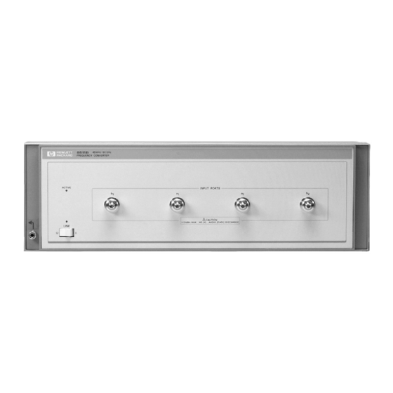
Page 21: Description And Characteristics Of The Instrument
Description and Characteristics of the Instrument The 8511B four channel frequency converter test set is designed to operate with all 8510 network analyzers. The test set provides a convenient means of customizing a test configuration for a variety of applications within the frequency range of 45 MHz to 50 GHz. - Page 22 General Information Description and Characteristics of the Instrument Figure 1-2 Measurement Setup Agilent 8511B Test Set Operating and Service Manual 1-7...
-
Page 23: Software And Hardware Requirements
HP BASIC for Windows, version 6.32 or later installed. • A CD-ROM drive. • Agilent 8511A/B and Antenna Measurement System Performance Verification Software. ® ® • Internet Explorer 4.0 or higher or Netscape 4.0 or higher. 1-8 Agilent 8511B Test Set Operating and Service Manual... -
Page 24: Options
Option 910 provides a duplicate manual at the time of purchase. Option 913 Option 913 supplies the parts required to rack mount the test set with handles attached. Refer to Chapter 3, “Installation” for additional information. Agilent 8511B Test Set Operating and Service Manual 1-9... -
Page 25: Service And Support Products
This option must be ordered when the instrument is ordered. Option 1BP Option 1BP adds a MIL-STD 45662A Certificate of Calibration and the corresponding calibration data to the instrument. This option must be ordered when the instrument is ordered. 1-10 Agilent 8511B Test Set Operating and Service Manual... -
Page 26: Accessories
2.4 mm connector tools and gauges. Agilent 85057B 2.4 mm Verification Kit Contains: precision airline mismatched airline 20 and 40 dB attenuators NIST (National Institute of Standards and Technology) traceable data and uncertainties. Agilent 8511B Test Set Operating and Service Manual 1-11... -
Page 27: Operating And Safety Precautions
These techniques for a static-safe work station should not be used when working on circuitry with a voltage potential greater than 500 volts. Figure 1-3 Example of a Static-Safe Work Station 1-12 Agilent 8511B Test Set Operating and Service Manual... -
Page 28: Reducing Esd Damage
90 N-cm (8 in.-lb.). • Do not torque anything to the source RF input on the back of your test set, with greater than 90 N-cm. (8 in.-lb.) of torque. Agilent 8511B Test Set Operating and Service Manual 1-13... -
Page 29: Service
The voltages in this test set warrant normal caution for operator safety. Nevertheless, service should be performed only by qualified personnel. Service strategy, troubleshooting procedures, replaceable parts and similar information for the 8511B test set is in this manual or the 8510 On-Site Service Manual. Specifications... -
Page 30: Miscellaneous
General Information Miscellaneous Miscellaneous Adjustments The Agilent 8511B had no adjustments. Specifically, no attempt should be made to adjust the samplers. Agilent 8511B Test Set Operating and Service Manual 1-15... - Page 31 General Information Miscellaneous 1-16 Agilent 8511B Test Set Operating and Service Manual...
-
Page 32: Specifications
8. Tested with sampler in non-conducting state. When diodes are turned on by the LO pulse, they present a short circuit across the sampler input port. This may affect the measured data. Agilent 8511B Test Set Operating and Service Manual 2-1... - Page 33 –5 dBm 1. The performance parameters listed are characteristic of the 8511B. They are typical or nominal figures and are not field verifiable. 2. Determined by 0.1 dB compression level and system low level peak noise. Low level peak noise measured with 50 ohm load at port and 1024 averaging factor.
-
Page 34: Dynamic Accuracy
Figure 2-1 Worst Case Dynamic Accuracy (Magnitude) Figure 2-2 Worst Case Dynamic Accuracy (Phase) Phase detector accuracy is better than 0.02 degrees, useful for measurements where only phase changes. Agilent 8511B Test Set Operating and Service Manual 2-3... - Page 35 460 mm x 133 mm x 609 mm (18.1 x 5.25 x 24 inches) Weight: 13 kg (29 lb) net; 17 kg (38 lb) shipping 1. Measured at the IF input to the 8510, not at the test set test ports. 2-4 Agilent 8511B Test Set Operating and Service Manual...
-
Page 36: Specification Assumptions
Specifications Specification Assumptions Specification Assumptions The specifications of the Agilent 8511B require that the following operating conditions are met: • All system instruments have reached stable operating temperature. • RF source: Agilent 83651A. When used with another recommended source, the performance specifications may differ from those for the 8510/8511/83651A configuration. -
Page 37: Recommended Test Equipment
85148A 2.4 mm 50 ohm load (f) no substitute 85138B 1. O = Operation; P = Performance test; T = Troubleshooting 2. Supplied in the 8511B Service Kit (part number 08511-60016) 2-6 Agilent 8511B Test Set Operating and Service Manual... -
Page 38: Installation
Contents of the 8511B Shipping Container Item Part Number Power Cord 8120-1348 Test set cable assembly 08510-60102 GPIB cable 8120-3445 Performance test software (CD-ROM) assembly 08511-60024 Agilent 8511B Operating and Service Manual 08511-90073 Agilent 8511B Test Set Operating and Service Manual 3-1... -
Page 39: Environmental Considerations
Preparation for Use Positioning the Test Set Typically the 8511B is placed under the 8510 network analyzer or the source whether it is rack-mounted or used on a bench. To install the flanges to rack mount the instrument (with or without handles) in a standard 19 inch rack refer to “Installing the Test Set in a System Rack”... -
Page 40: Installing The Test Set In A System Rack
Installing the Test Set in a System Rack The recommended system rack is the Agilent 85043C. Instructions for rack-mounting the 8511B test set in a system configuration with the 8510 are provided in the “Installation” chapter of the Agilent 8510 On-Site Service Manual and in the Agilent 85043C System Rack Manual (part number 85043-90022). - Page 41 Installation Installing the Test Set in a System Rack Figure 3-1 Attaching Rack-Mounting Hardware 3-4 Agilent 8511B Test Set Operating and Service Manual...
-
Page 42: Installing The Test Set On A Bench
Refer to “Operating and Safety Precautions” on page 1-12. A grounding receptacle is provided on the test set as an alternate grounding point for your anti-static wrist-strap. Agilent 8511B Test Set Operating and Service Manual 3-5... -
Page 43: Connecting The Test Set
TEST SET INTERCONNECT connector on the rear panel of the Agilent 85102 IF detector. 3. Connect the system bus cable from the 8511B J12 8510 SYSTEM BUS connector to the 8510 INTERCONNECT connector of the 85101 display/processor. The test set IF interconnect cable and the system bus cable transmit control signals between the test set and the network analyzer. -
Page 44: Connecting The Test Set
Installation Connecting the Test Set Connecting the Test Set Figure 3-2 Connecting the Test Set in a System Configuration Agilent 8511B Test Set Operating and Service Manual 3-7... -
Page 45: Packaging
4. If shipping to an Agilent office or service center, complete and attach a service tag (provided in the 8510 manual set). In any correspondence with Agilent, refer to the test set by full model and serial number. 3-8 Agilent 8511B Test Set Operating and Service Manual... -
Page 46: Operation
Port a or a must be used for system phaselock. These ports are precision 2.4 mm connectors and all connections must be torqued to no more than 90 N-cm (8 in-lb). Agilent 8511B Test Set Operating and Service Manual 4-1... -
Page 47: Rear Panel Features
Decimal 20 (off-off-on-off-on, from left to right) is the default setting (see Figure 6-4 on page 6-6). 5. J12 8510 System Bus Connector. This connector is used for GPIB communications with the Agilent 85101 display/processor. 4-2 Agilent 8511B Test Set Operating and Service Manual... -
Page 48: Operator's Check
Operation Operator’s Check Operator’s Check The purpose of this check is to confirm that the Agilent 8511B functions properly as part of an 8510 system. Table 4-1 Necessary Equipment Description Agilent Model or Part Number Network analyzer system 8510,B,C Semi-rigid cables (2) -
Page 49: A1 And B1 Test
Connect the other end of the RF source cable to the output of the source. Rotate the semi-rigid cables to the required position for connection to ports a and b . Tighten all connections. Figure 4-3 Hardware Configuration for Operator’s Check 4-4 Agilent 8511B Test Set Operating and Service Manual... -
Page 50: A2 And B2 Test
4. If any of the traces are not within the limits noted above, check all of the connections and repeat the above procedure. If symptoms persist, refer to the “Service and Equipment Overview” chapter in the Agilent 8510C On-Site Service Manual. Agilent 8511B Test Set Operating and Service Manual 4-5... -
Page 51: Controlling Multiple Test Sets
1 can apply its IF to the 8510, or it can switch to pass the IF from test set number 2 through the J10 TEST SET INTERCONNECT to the 8510. 4-6 Agilent 8511B Test Set Operating and Service Manual... - Page 52 RF and IF Switching with Two Test Sets Table 4-2 Agilent 33311C Coaxial Switch Positions with Two Test Sets New ADDRESS of Test Set Test Set Selected 33311C Coaxial Switch Port Selected Port 1 Port 2 Agilent 8511B Test Set Operating and Service Manual 4-7...
-
Page 53: Installation
The last test set in the chain does not require Option 001. If the RF coaxial switch(s) is not incorporated into the system, then the RF input to the test set must be manually switched to the active test set. 4-8 Agilent 8511B Test Set Operating and Service Manual... -
Page 54: Operation
J11 TEST SET INTERCONNECT. When the test set is inactive, the IF signals appearing at J10 are passed through to J11 and on to the next test set or the analyzer. Agilent 8511B Test Set Operating and Service Manual 4-9... -
Page 55: Test Set Address
RF output of the network analyzer source. The exact command issued depends upon the new value of the [ADDRESS of function, also shown in Figure 4-5 on page 4-7 Figure 4-6 on TEST SET] page 4-11. 4-10 Agilent 8511B Test Set Operating and Service Manual... - Page 56 33311C Coaxial Switch Port Selected New ADDRESS of Test Set Test Set Selected Switch #1 Switch #2 Port 1 Port 1 Port 1 Port 2 Port 2 Port 1 Port 2 Port 2 Agilent 8511B Test Set Operating and Service Manual 4-11...
-
Page 57: Measurement Calibration
8511 in the chain, select it as the active test set and proceed as usual. Refer to the Agilent 8510 On-Site Service Manual for the performance verification procedure. 4-12 Agilent 8511B Test Set Operating and Service Manual... -
Page 58: Performance Tests
Performance Tests The Agilent 8511B ships with the Agilent 8511A/B and Antenna Measurement System Performance Verification Software assembly (part number 08511-60024). This assembly includes performance verification software with on-line help and an installation and getting started manual (part number 5962-0493). -
Page 59: Port Return Loss
RF source power, and the line power to it. 3. Turn on the 8511B and treat it like a device under test. You will use the 8517B test set to make S11 measurements of each port on the 8511B. -
Page 60: Test Set Troubleshooting
Theory of Operation The RF section of an 8511B frequency converter test set consists of a voltage-tuned oscillator (VTO), a four-way power splitter and four samplers. The frequency converter operates within the frequency range of 45 MHz to 50 GHz. - Page 61 They may or may not continue to function if subjected to an electrostatic discharge. In any case, an electrostatic discharge will impair the reliability of these assemblies. Always perform the steps in order. 6-2 Agilent 8511B Test Set Operating and Service Manual...
-
Page 62: Equipment Needed But Not Supplied
Equipment Needed but Not Supplied Table 6-1 Needed Equipment Equipment Agilent Part Number 1 point Posidriv screwdriver 8710-0899 2 point Posidriv screwdriver 8710-0900 Service adapter 85105-60210 5/16 in torque wrench 8710-1655 Oscilloscope 1740A Agilent 8511B Test Set Operating and Service Manual 6-3... -
Page 63: Troubleshooting Sequence
Test Set Troubleshooting Troubleshooting Sequence Troubleshooting Sequence Use this flowchart and the following procedures to determine the faulty assembly. Figure 6-2 Troubleshooting Flowchart 6-4 Agilent 8511B Test Set Operating and Service Manual... -
Page 64: Troubleshooting Procedures
Test Set Troubleshooting Troubleshooting Procedures Troubleshooting Procedures Procedure 1 A15 Regulator Figure 6-3 Power Supply Fuses and Test Points Agilent 8511B Test Set Operating and Service Manual 6-5... -
Page 65: A15 Primary Regulator Board Assembly
The locations of the fuses used in the test set are illustrated in Figure 6-3 on page 6-5. The values of these fuses and their part numbers may be found in Chapter 8, “Replaceable Parts”. 6-6 Agilent 8511B Test Set Operating and Service Manual... -
Page 66: Procedure 2
To determine what part of the self-test has failed, note which LEDs on the A4 board are lit, see Figure 6-5. Agilent 8511B Test Set Operating and Service Manual 6-7... - Page 67 Test Set Troubleshooting Troubleshooting Procedures Figure 6-5 Location of Self-Test Indicators 6-8 Agilent 8511B Test Set Operating and Service Manual...
-
Page 68: If The Self-Test Fails To Run
GPIB board is most probably faulty. • all LEDs flash briefly and go off • all LEDs flash briefly and stay on • ACTIVE LED goes on too soon • ACTIVE LED does not go on Agilent 8511B Test Set Operating and Service Manual 6-9... -
Page 69: Agilent 85102 If
If one or more channels look bad. The problem is most probably with the 85102. Refer to the Agilent 8510 On-Site Service Manual for information on troubleshooting the 85102. 6-10 Agilent 8511B Test Set Operating and Service Manual... - Page 72 Table 6-10 Test Sets Interconnect Table (1 of 2) A3 VTO Signal Enters A1 Front A2 IF A14 VTO/ A16 Step A17 Step A20 Rear → Summing A4 GPIB Attenuator/ (Assembly) Panel Multiplexer Sampler Sampler Sampler Sampler Driver Regulator Attenuator 1 Attenuator 2 Panel Switch...
- Page 73 Table 6-11 Test Sets Interconnect Table (2 of 2) A3 VTO Signal Enters A1 Front A2 IF A14 VTO/ A16 Step A17 Step A20 Rear → Summing A4 GPIB Attenuator/ (Assembly) Panel Multiplexer Sampler Sampler Sampler Sampler Driver Regulator Attenuator 1 Attenuator 2 Panel Switch...
-
Page 74: Replacement Procedures
Use Figure 7-1 on page 7-2 But Not Supplied locate the assemblies in the Agilent 8511B test set. Table 7-1 Equipment Needed to Replace Test Set Major Assemblies Tools... - Page 75 Replacement Procedures Figure 7-1 Assembly Location Diagram 7-2 Agilent 8511B Test Set Operating and Service Manual...
-
Page 76: Preliminary Precautions
5. Torque the 2.4 mm connections to 90 N-cm (8 in-lb). 6. Exercise caution when handling semi-rigid coax cables. They are easily bent. 7. To install a part, reverse the appropriate procedure. Agilent 8511B Test Set Operating and Service Manual 7-3... -
Page 77: Replacing The Frequency Converter
100 watt resistor. Use the resistor to discharge each capacitor terminal (large pozidriv screw on the bottom side of the test set). Each capacitor has two 7-4 Agilent 8511B Test Set Operating and Service Manual... - Page 78 Discharge all capacitor terminals. It takes approximately six seconds to discharge each capacitor. 4. To remove a capacitor, remove the corresponding pair of screws and pull the capacitor out of the test set. Agilent 8511B Test Set Operating and Service Manual 7-5...
-
Page 79: Repairing A 2.4 Mm Rf Connector
6. Clean the mating surfaces with alcohol and lint-free swabs. 7. Check the pin depth of the gold nose connector. The pin depth specification is 0.0000 to +0.0030 inch. 8. Reconnect the cables disconnected in step 1. 7-6 Agilent 8511B Test Set Operating and Service Manual... -
Page 80: B1 Fan
8. Using a small pozidriv screwdriver, remove the four screws that hold the fan to the rear panel and remove the fan. Agilent 8511B Test Set Operating and Service Manual 7-7... -
Page 81: T1 Power Transformer
8. Remove the transformer. When you replace the transformer, refer to Figure 7-3 for the location of the wires connected to the line module. Figure 7-3 Wire Connections to the Line Module FL1 7-8 Agilent 8511B Test Set Operating and Service Manual... -
Page 82: Replaceable Parts
To order a part that is not listed, include the instrument model number, complete serial number, description and function of the part, and quantity required. Send the order to the nearest Agilent office. Agilent 8511B Test Set Operating and Service Manual 8-1... -
Page 83: Exchange Assemblies Available
• A4 = GPIB board assembly • A10, A11, A12, A13 plus A14 = sampler assembly (inputs bl, b2, a1, a2 and A14 VTO driver) • A15 = regulator board assembly 8-2 Agilent 8511B Test Set Operating and Service Manual... - Page 84 Replaceable Parts Figure 8-1 Low Cost Rebuilt-Exchange Procedure Agilent 8511B Test Set Operating and Service Manual 8-3...
- Page 85 Replaceable Parts Figure 8-2 Major Assemblies 8-4 Agilent 8511B Test Set Operating and Service Manual...
- Page 86 Replaceable Parts Figure 8-3 Semi-Rigid Cables Agilent 8511B Test Set Operating and Service Manual 8-5...
- Page 87 Replaceable Parts Figure 8-4 Flexible RF Cables 8-6 Agilent 8511B Test Set Operating and Service Manual...
- Page 88 Replaceable Parts Figure 8-5 Detailed Views of Rear Panel Miscellaneous Parts Agilent 8511B Test Set Operating and Service Manual 8-7...
- Page 89 Replaceable Parts Figure 8-6 Miscellaneous Motherboard Parts 8-8 Agilent 8511B Test Set Operating and Service Manual...
-
Page 90: Replaceable Parts Lists
Cable assembly J10 to J11 08511-20021 Cable assembly A10 to front panel 08511-20024 Cable assembly A11 to front panel 08511-20022 Cable assembly A12 to front panel 08511-20023 Cable assembly A13 to front panel Agilent 8511B Test Set Operating and Service Manual 8-9... - Page 91 Insulator brace 08513-00037 Bracket enclosure 08513-00040 Cover (test set top) 08513-00041 Cover (side PERF) 08513-20013 Brace (deck) 08513-20015 Mounting bar 08513-60156 ENC assembly doubler 08513-65002 INTMD board assembly 08517-60005 Rear panel assembly 8-10 Agilent 8511B Test Set Operating and Service Manual...
- Page 92 Front frame cover 5041-8801 Foot FM .5 M 5041-8821 Rear panel standoff 5062-3747 Cover (bottom) 5062-3757 Cover (side)5062-3989 5062-3989 Front handle kit 5062-7243 Connector assembly (bulkhead) 5962-0476 Certificate of Calibration 85120-00041 Cover (blank) Agilent 8511B Test Set Operating and Service Manual 8-11...
- Page 93 Replaceable Parts Figure 8-7 Parts Unique to Option 001 8-12 Agilent 8511B Test Set Operating and Service Manual...
- Page 94 Cable assembly A2J11-J11A3 08513-60129 Cable SMB/MSC 711W 08513-60130 Cable SMB/MSC 456W 08513-60131 Cable SMB/MSC 762W 08513-60132 Cable SMB/MSC 457W 08513-60135 Cable SMB/MSC 610W 08513-60137 Cable SMB/MSC 4836W 08513-60139 Cable SMB/MSC 457W Agilent 8511B Test Set Operating and Service Manual 8-13...