Table of Contents
Advertisement
Advertisement
Table of Contents

Related Manuals for SawStop CTS-015


Summary of Contents for SawStop CTS-015
- Page 1 SERVICE DOCUMENT CTS Service Manual December, 2022...
- Page 2 SawStop, the SawStop blade logo, and the configuration of this product are either registered trademarks or trademarks of SawStop, LLC. Software copyright by SawStop, LLC. All rights reserved. Protected by one or more of the following U.S. patents: 6857345, 6997090, 7024975, 7098800, 7100483, 7197969, 7210383, 7225712, 7231856,...
- Page 3 This warranty is void if the saw or any portion of the saw is modified without the prior written permission of SawStop, LLC, or if the saw is located or has been operated outside of the country where the authorized SawStop distributor from whom the saw was purchased resides.
-
Page 4: Table Of Contents
Table of Contents Motor Cover (CTS-015) Trunnion Motor Cover (CTS-016) Dust Shroud (CTS-013) Fence Rails (CTS-002, CTS-003) Fence Rail Guides "Pucks" (CTS-005) Rail Lock Handle (CTS-010) Rail Lock Pinion (CTS-011) Elevation Control Shaft (CTS-036) Rail Lock Rocker (CTS-012) Switch Box Assembly (CTS-038) -
Page 5: Motor Cover (Cts-015)
Motor Cover (CTS-015) Motor Cover (CTS-015) Use the instructions in this chapter to install the Motor Cover service kit you received. WARNING: To ensure safety during maintenance, disconnect all electrical power to the saw and remove the saw blade. NOTE:... - Page 6 Motor Cover (CTS-015) Exploded View Service Kit Parts List (CTS-015) ITEM DESCRIPTION Motor Cover Screw - M4 x 1.8, 16mm, Button Head, Phillips Tools Required #2 Phillips Head Screwdriver Prerequisites None. CTS Service Manual...
- Page 7 Motor Cover (CTS-015) Disassembly Steps IMPORTANT: To ensure thorough understanding, please read the instructions all the way through before starting this procedure. 1. At the front of the saw, adjust the CTS bevel adjustment to 45 degrees. 2. At the rear of the saw, unlatch and remove the Accessory Storage Compartment.
- Page 8 Motor Cover (CTS-015) 3. Fasteners are now revealed that secure part of the Motor Cover [1] place. Remove the three Screws - M4 x 1.8, 16mm, Button Head, Phillips [2] indicated in the photo. 4. From the left side of your CTS, remove the two Screws - M4 x 1.8, 16mm, Button...
- Page 9 Motor Cover (CTS-015) 6. Slide the motor cover down and remove it through the bottom of the frame of your CTS. Once removed, set it aside if it is to be re-installed later. Discard it if a replacement has been provided in the service kit you received from SawStop.
-
Page 10: Trunnion Motor Cover (Cts-016)
Trunnion Motor Cover (CTS-016) Trunnion Motor Cover (CTS-016) Use the instructions in this chapter to install the Trunnion Motor Cover service kit you received. WARNING: To ensure safety during maintenance, disconnect all electrical power to the saw and remove the saw blade. NOTE: For an optimal experience using this service manual, begin maintenance on your saw by starting with the chapter most directly associated with the CTS service kit you received... - Page 11 For now, perform ONLY the disassembly steps in the following chapters in the order listed, then return to this chapter for the remaining instructions. Motor Cover (CTS-015) NOTE: If you have been directed to this chapter from another part of this manual, the prerequisites...
- Page 12 Trunnion Motor Cover (CTS-016) section of the chapter you began with might list one or more of the same prerequisites seen above. If you've already completed a listed disassembly, move on to the next instruction. Disassembly Steps IMPORTANT: To ensure thorough understanding, please read the instructions all the way through before starting this procedure.
- Page 13 Discard it if a replacement has been provided in the service kit you received from SawStop. Assembly Steps 1. Perform the Disassembly Steps described immediately above in reverse order. If a service kit containing new parts to replace those removed above was provided, use only the new parts during re-assembly.
-
Page 14: Dust Shroud (Cts-013)
Dust Shroud (CTS-013) Dust Shroud (CTS-013) Use the instructions in this chapter to install the Dust Shroud service kit you received. WARNING: To ensure safety during maintenance, disconnect all electrical power to the saw and remove the saw blade. NOTE: For an optimal experience using this service manual, begin maintenance on your saw by starting with the chapter most directly associated with the CTS service kit you received containing replacement parts. - Page 15 Dust Shroud (CTS-013) Exploded View Service Kit Parts List (CTS-013) ITEM DESCRIPTION Dust Shroud Assembly Screw - M5x2.2, 45mm, Pan Head, Phillips, Thread Cutting Bolt -M4x0.7, 8mm, Flat Washer, Pan Head, Phillips Tools Required #2 Phillips Screwdriver Prerequisites Disassembly steps for maintenance associated with the service kit you received requires the following prerequisites.
- Page 16 Dust Shroud (CTS-013) return to this chapter for the remaining instructions. Trunnion Motor Cover (CTS-016) Motor Cover (CTS-015) NOTE: If you have been directed to this chapter from another part of this manual, the prerequisites section of the chapter you began with might list one or more of the same prerequisites seen above.
- Page 17 Discard it if a replacement has been provided in the service kit you received from SawStop. Assembly Steps 1. Perform the Disassembly Steps described immediately above in reverse order. If a service kit containing new parts to replace those removed above was provided, use only the new parts during re-assembly.
-
Page 18: Fence Rails (Cts-002, Cts-003)
Fence Rails (CTS-002, CTS-003) Fence Rails (CTS-002, CTS-003) Use the instructions in this chapter to install the aluminum extruded fence rail (front or rear) service kit you received. WARNING: To ensure safety during maintenance, disconnect all electrical power to the saw and remove the saw blade. - Page 19 Fence Rails (CTS-002, CTS-003) Service Kit Parts List - Front Rail (CTS-002) ITEM DESCRIPTION Rail - Front Square Nut - M6 x 1.0mm Bolt - M6 x 1.0mm, Hex Flange Head Lens - Fence Position Indicator Bolt - M4x0.7mm, Flat Washer, Pan Head, Phillips Exploded View - Rear Fence Rail Service Kit Parts List - Rear Rail (CTS-003) ITEM...
- Page 20 Fence Rails (CTS-002, CTS-003) Tools Required 4mm Allen Wrench #2 Phillips Head Screwdriver Prerequisites None. Disassembly Steps IMPORTANT: To ensure thorough understanding, please read the instructions all the way through before starting this procedure. 1. Unlock the fence rails. CTS Service Manual...
- Page 21 Fence Rails (CTS-002, CTS-003) 2. Unlatch and remove the fence assembly. 3. Release the front of the Trunnion, Rail Lock Assembly from the saw by removing the two screws shown using a #2 Phillips screwdriver. Perform this step at both front and rear of your CTS. CTS Service Manual...
- Page 22 1. Perform the Disassembly Steps described immediately above in reverse order but this time, you'll use the new parts contained in the service kit you received from SawStop (If provided). 2. Install the fasteners into the outward facing T-track of the fence rail extrusion.
- Page 23 Fence Rails (CTS-002, CTS-003) Rear Rail Hardware Placement IMPORTANT: Precision placement of this hardware is crucial to the cutting accuracy of your CTS. See Inspection Steps below for more information. 3. If a front fence rail was included in your service kit, install the with the included Lens - Fence Position Indicator...
- Page 24 Manual. A companion video is also available detailing the process for aligning the fence and the blade to the miter slot. Watch: SawStop Service Tip: Aligning the Blade and Rip Fence to the Miter Slots on the Compact Table CTS Service Manual...
-
Page 25: Fence Rail Guides "Pucks" (Cts-005)
Fence Rail Guides "Pucks" (CTS-005) Fence Rail Guides "Pucks" (CTS-005) Use the instructions in this chapter to install the Puck Service Kit you received. WARNING: To ensure safety during maintenance, disconnect all electrical power to the saw and remove the saw blade. NOTE: For an optimal experience using this service manual, begin maintenance on your saw by starting with the chapter most directly associated with the CTS service kit you received... - Page 26 Fence Rail Guides "Pucks" (CTS-005) Exploded View Service Kit Parts List (CTS-005) ITEM DESCRIPTION Puck - End, Inner Rail Bolt - M5 x 0.8, 14mm, Flat Head, Socket Puck - Base, Inner Rail Bolt - M5 x 0.8, 16mm, Socket Head Cap, Loctite Puck - Upper Inner Rail Bolt - M4x0.7, 20mm, Socket Head Cap Lock Nut - M4 x 0.7...
- Page 27 Fence Rail Guides "Pucks" (CTS-005) Tools Required 3mm Allen Wrench 4mm Allen Wrench #2 Phillips Head Screwdriver 8mm Socket Wrench Prerequisites Disassembly steps for maintenance associated with the service kit you received requires the following prerequisites. For now, perform ONLY the disassembly steps in the following chapters in the order listed, then return to this chapter for the remaining instructions.
- Page 28 Fence Rail Guides "Pucks" (CTS-005) Disassembly Steps IMPORTANT: To ensure thorough understanding, please read the instructions all the way through before starting this procedure. 1. Begin by removing the worn circular pucks from the front of the saw. Remove the Lock Nuts - M4 x 0.7 [7] behind both Pucks - End, Inner Rail [1]...
- Page 29 5. Once removed, set all the parts aside if they are to be reinstalled. If new parts have been provided in the service kit you received from SawStop, discard all of the original hardware (including nuts and bolts) and use only new parts provided with the service kit.
-
Page 30: Rail Lock Handle (Cts-010)
Rail Lock Handle (CTS-010) Rail Lock Handle (CTS-010) Use the instructions in this chapter to install the Rail Lock Handle service kit that you received. WARNING: To ensure safety during maintenance, disconnect all electrical power to the saw and remove the saw blade. - Page 31 Rail Lock Handle (CTS-010) Exploded View Service Kit Parts List (CTS-010) ITEM DESCRIPTION Sleeve - Rail Lock Handle Handle - Rail Lock Pin - Spring, 4 x 18 Spring - Rail Lock, Handle Tools Required Hammer 3mm Punch Prerequisites None. CTS Service Manual...
- Page 32 Rail Lock Handle (CTS-010) Disassembly Steps IMPORTANT: To ensure thorough understanding, please read the instructions all the way through before starting this procedure. 1. Unlock the fence position by pulling the outward. Handle -Rail Lock [2] 2. Place the 3mm punch against the Pin - Spring, 4 x 18 [3] CTS Service Manual...
- Page 33 Rail Lock Handle (CTS-010) 3. Strike the punch with a hammer until the pin is removed. Consider cutting a piece of scrap wood to support the shaft during this step. 4. Gently remove the punch then remove the , the Handle - Rail Lock [2] Spring - Rail Lock, Handle [4] finally the...
- Page 34 Rail Lock Handle (CTS-010) Inspection Steps 1. Confirm Rail Lock Handle operation to verify positive lock and unlock functionality. It should not slide freely but offer some resistance when the knob is pushed in (lock) or pulled out (unlock). Adjust the rocker tension adjustment nut shown until the lock and unlock force is restored to its former behavior prior to performing this maintenance.
-
Page 35: Rail Lock Pinion (Cts-011)
Rail Lock Pinion (CTS-011) Rail Lock Pinion (CTS-011) Use the instructions in this chapter to install the Rail Lock Pinion service kit that you received. WARNING: To ensure safety during maintenance, disconnect all electrical power to the saw and remove the saw blade. - Page 36 Rail Lock Pinion (CTS-011) Exploded View Service Kit Parts List (CTS-011) ITEM DESCRIPTION Main Rail Lock Pinion Assembly Guide - Shaft Bushing, Rocker Bolt - M4 x 0.7, 30mm, Button Head, Phillips Bolt - M5x0.8, 14mm, Locktite, Lock Washer, Button Head, Phillips Rear Rail Lock Pinion Assembly Tools Required Needle Nose Pliers...
- Page 37 Rail Lock Pinion (CTS-011) Prerequisites Disassembly steps for maintenance associated with the service kit you received requires the following prerequisites. For now, perform ONLY the disassembly steps in the following chapters in the order listed, then return to this chapter for the remaining instructions. Rail Lock Handle (CTS-010) NOTE: If you have been directed to this chapter from another part of this manual, the prerequisites...
- Page 38 Rail Lock Pinion (CTS-011) 2. Next, remove the angled clevis pin. Set the clevis pin aside for later reinstallation. 3. Using a #2 Phillips head screwdriver, remove both Bolt - M5x0.8, 14mm, Locktite, Lock Washer, Button Head, from the locations indicated Phillips [4] in the photo.
- Page 39 Assembly Steps Perform the Disassembly Steps described immediately above in reverse order but this time, you'll use only the new parts contained in the service kit you received from SawStop (if supplied). There are certain details to be observed during re-assembly: 1.
- Page 40 Rail Lock Pinion (CTS-011) 3. Ensure the front and rear aluminum extruded fence rails are aligned with one edge of the saw table, then re- attach the front and rear vertical shaft alignment guides using a #2 Phillips head screwdriver and four Bolt - M5x0.8, 14mm, Locktite, Lock Washer, Button Head, Phillips [4]...
- Page 41 Rail Lock Pinion (CTS-011) Inspection Steps 1. Confirm Rail Lock Handle operation to verify positive lock and unlock functionality. It should not slide freely but offer some resistance when the knob is pushed in (lock) or pulled out (unlock). Adjust the rocker tension adjustment nut shown until the lock and unlock force is restored to its former behavior prior to performing this maintenance.
-
Page 42: Elevation Control Shaft (Cts-036)
Elevation Control Shaft (CTS-036) Elevation Control Shaft (CTS-036) Use the instructions in this chapter to install the Elevation Control Shaft service kit you received. WARNING: To ensure safety during maintenance, disconnect all electrical power to the saw and remove the saw blade. NOTE: For an optimal experience using this service manual, begin maintenance on your saw by starting with the chapter most directly associated with the CTS service kit you received... - Page 43 Elevation Control Shaft (CTS-036) Exploded View Service Kit Parts List (CTS-036) ITEM DESCRIPTION Elevation Control Shaft Retaining Ring - E-Style, 7mm Flat Washer - M9, 18mm x 0.5mm Washer - Elevation Handle Lock Nut - M8 x 1.25mm CTS Service Manual...
- Page 44 Elevation Control Shaft (CTS-036) Tools Required Needle Nose Pliers 13mm Socket Wrench Flat Head Screwdriver 2mm Allen Wrench Prerequisites Disassembly steps for maintenance associated with the service kit you received requires the following prerequisites. For now, perform ONLY the disassembly steps in the following chapters in the order listed, then return to this chapter for the remaining instructions.
- Page 45 Elevation Control Shaft (CTS-036) 1. Watch end of the that is Elevation Control Shaft [1] fitted to the U-joint as you rotate the elevation adjustment at the front of your CTS. Stop rotating when the head of the set screw that pins the shaft to the U-Joint is visible.
- Page 46 Once removed, set it aside if it is to be re- installed later. Discard it if a replacement has been provided in the service kit you received from SawStop. Assembly Steps 1. Perform the Disassembly Steps described immediately above in reverse order. If a service kit containing new parts to replace those removed above was provided, use only the new parts during re-assembly.
- Page 47 Elevation Control Shaft (CTS-036) Inspection Steps 1. When re-installing the set screw to join the elevation shaft to the U-joint, confirm that the set screw is flush and does not protrude from either side of the U-Joint. 2. Rotate the bevel and elevation adjustment knob through its full range of motion to confirm the blade height can be fully extended, and fully retracted.
-
Page 48: Rail Lock Rocker (Cts-012)
Rail Lock Rocker (CTS-012) Rail Lock Rocker (CTS-012) Use the instructions in this chapter to install the Rail Lock Rocker service kit you received. WARNING: To ensure safety during maintenance, disconnect all electrical power to the saw and remove the saw blade. NOTE: For an optimal experience using this service manual, begin maintenance on your saw by starting with the chapter most directly associated with the CTS service kit you received... - Page 49 Rail Lock Rocker (CTS-012) Exploded View Service Kit Parts List (CTS-012) ITEM DESCRIPTION Rail Lock Rocker Assembly Spring - Rail Lock, Pivot Return Flat Washer - M8, 16mm x 1.5mm Spring - 30mm, Rail Lock, Rocker Rail Lock Link Assembly Bushing - M8 x 1.25, 50mm, Partially Threaded, Rail Lock, Nut Nut - M8 x 1.25, 13mm, Hex Strap - Rail Lock...
- Page 50 Rail Lock Rocker (CTS-012) Disassembly Steps IMPORTANT: To ensure thorough understanding, please read the instructions all the way through before starting this procedure. 1. Using a #2 Phillips head screwdriver, remove both bolts from the front shaft alignment guide for the Rail Lock Pinion.
- Page 51 Discard it if a replacement has been provided in the service kit you received from SawStop. Assembly Steps 1. Perform the Disassembly Steps described immediately above in reverse order. If a service kit containing new parts to replace those removed above was provided, use only the new parts during re-assembly.
- Page 52 Rail Lock Rocker (CTS-012) Inspection Steps 1. Confirm Rail Lock Handle operation to verify positive lock and unlock functionality. It should not slide freely but offer some resistance when the knob is pushed in (lock) or pulled out (unlock). Adjust the rocker tension adjustment nut and bushing shown until the lock and unlock force is restored to its former behavior prior to performing this maintenance.
-
Page 53: Switch Box Assembly (Cts-038)
Switch Box Assembly (CTS-038) Switch Box Assembly (CTS-038) Use the instructions in this chapter to install the Switch Box service kit you received. WARNING: To ensure safety during maintenance, disconnect all electrical power to the saw and remove the saw blade. NOTE: For an optimal experience using this service manual, begin maintenance on your saw by starting with the chapter most directly associated with the CTS service kit you received... - Page 54 Disassembly steps for maintenance associated with the service kit you received requires the following prerequisites. For now, perform ONLY the disassembly steps in the following chapters in the order listed, then return to this chapter for the remaining instructions. Motor Cover (CTS-015) CTS Service Manual...
- Page 55 Switch Box Assembly (CTS-038) Disassembly Steps IMPORTANT: To ensure thorough understanding, please read the instructions all the way through before starting this procedure. 1. Remove the retaining panel behind the by removing the Switch Box Assembly [1] screws indicated in the photo. A Phillips Head Screwdriver is required.
- Page 56 Switch Box Assembly (CTS-038) 3. Using a #2 Phillips screwdriver, remove the bevel indicator. 4. Using a T20 Torx driver, remove the eight bolts that secure the front panel. 5. Once free, slide the front panel upward to clear the .
- Page 57 Once removed, set it aside if it is to be re-installed later. Discard it if a replacement has been provided in the service kit you received from SawStop. Assembly Steps 1. Perform the Disassembly Steps described immediately above in reverse order. If a service kit containing new parts to replace those removed above was provided, use only the new parts during re-assembly.
-
Page 58: Alignment Block (Cts-032)
Alignment Block (CTS-032) Alignment Block (CTS-032) Use the instructions in this chapter to install the Alignment Block service kit you received. WARNING: To ensure safety during maintenance, disconnect all electrical power to the saw and remove the saw blade. NOTE: For an optimal experience using this service manual, begin maintenance on your saw by starting with the chapter most directly associated with the CTS service kit you received containing replacement parts. - Page 59 Alignment Block (CTS-032) Exploded View Service Kit Parts List (CTS-032) ITEM DESCRIPTION Alignment Block Assy, Friction Plug Bolt - M6 x 1.0, 55mm, Socket Head Cap Lock Nut - M6 x 1.0mm Tools Required 5mm Allen Wrench 10mm Socket Wrench Flat Blade Screwdriver Square CTS Service Manual...
- Page 60 Disassembly steps for maintenance associated with the service kit you received requires the following prerequisites. For now, perform ONLY the disassembly steps in the following chapters in the order listed, then return to this chapter for the remaining instructions. Motor Cover (CTS-015) 2. Remove the saw blade - (Refer to your CTS Owner's...
- Page 61 Alignment Block (CTS-032) 3. With an upward prying motion, hold the handle of the screwdriver against the underside of the saw table, as you rotate the elevation adjustment at the front of your CTS to lower the blade adjustment. This will assist with prying the black hook from the silver pin it straddles.
- Page 62 Once removed, set it aside if it is to be re-installed later. Discard it if a replacement has been provided in the service kit you received from SawStop. Assembly Steps 1. Perform the Disassembly Steps described immediately above in reverse order. If a service kit containing new parts to replace those removed above was provided, use only the new parts during re-assembly.
- Page 63 Watch: SawStop Service Tip: Aligning the Blade and Rip Fence to the Miter Slots on the Compact Table 3. Use any angle measuring device or standard to confirm bevel accuracy at 0° and 45° settings. If needed, adjust the red, metal arrow at the protractor on the front of your CTS using a #2 Phillips head screwdriver.
-
Page 64: U-Joint (Cts-037)
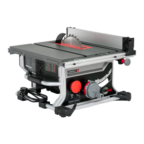
CTS in its normal, upright orientation. Description The U-Joint is part of the mechanism associated with blade height adjustment on your SawStop Compact Table Saw. It provides a 90 degree junction between the Elevation Control Shaft and the worm drive shaft. - Page 65 U-Joint (CTS-037) Exploded View Service Kit Parts List (CTS-037) ITEM DESCRIPTION U-Joint Assembly - Elevation Control Set Screw - M4 x 0.7, 25mm, Socket Head Tools Required 2mm Allen Wrench Flat Head Screwdriver Prerequisites Disassembly steps for maintenance associated with the service kit you received requires the following prerequisites.
- Page 66 U-Joint (CTS-037) Disassembly Steps IMPORTANT: To ensure thorough understanding, please read the instructions all the way through before starting this procedure. 1. Locate the U-joint just beneat the brake cartridge. 2. There are two set screws that link the U-joint the rest of the elevation apparatus. Both set screws must be removed.
- Page 67 5. Remove the U-Joint. Handle carefully as it will be greasy. Once removed, set it aside if it is to be re-installed later. Discard it if a replacement has been provided in the service kit you received from SawStop. CTS Service Manual...
- Page 68 Assembly Steps 1. Perform the Disassembly Steps described immediately above in reverse order but this time, you'll use only the new parts contained in the service kit you received from SawStop (if supplied). Here are a few tips regarding reassembly: a.
-
Page 69: Retraction Bracket (Cts-029)
Retraction Bracket (CTS-029) Retraction Bracket (CTS-029) Use the instructions in this chapter to install the Retraction Bracket service kit you received. WARNING: To ensure safety during maintenance, disconnect all electrical power to the saw and remove the saw blade. NOTE: For an optimal experience using this service manual, begin maintenance on your saw by starting with the chapter most directly associated with the CTS service kit you received containing replacement parts. - Page 70 Retraction Bracket (CTS-029) Exploded View Service Kit Parts List (CTS-029) ITEM DESCRIPTION Retraction Bracket Flat Washer - M6, 20mm x 1.5mm Lock Washer - M6 Bolt - M6 x 1.0mm, 16mm, Button Head, Socket Bolt - M6 x 1.0mm, 10mm, Cap Head, Socket CTS Service Manual...
- Page 71 For now, perform ONLY the disassembly steps in the following chapters in the order listed, then return to this chapter for the remaining instructions. Motor Cover (CTS-015) 2. Remove the Blade Guard 3. Remove the saw blade - (Refer to your CTS Owner's...
- Page 72 Retraction Bracket (CTS-029) Disassembly Steps IMPORTANT: To ensure thorough understanding, please read the instructions all the way through before starting this procedure. 1. Rotate the elevation adjustment at the front of your CTS clockwise to raise the blade adjustment to it's highest position.
- Page 73 Retraction Bracket (CTS-029) 3. With an upward prying motion, hold the handle of the screwdriver against the underside of the saw table, as you rotate the elevation adjustment at the front of your CTS to lower the blade adjustment. This will assist with prying the black hook from the silver pin it straddles.
- Page 74 Retraction Bracket [1] and can be removed from your CTS. Once removed, set it aside if it is to be re-installed later. Discard it if a replacement has been provided in the service kit you received from SawStop. CTS Service Manual...
- Page 75 Retraction Bracket (CTS-029) Assembly Steps 1. Perform the Disassembly Steps 4-6 above in reverse order. 2. Rotate the elevation adjustment at the front of your CTS to drop the blade adjustment to it's lowest position. Toward the bottom of the range of travel, you'll feel some resistance but continue to lower the assembly until the retraction block re-engages with the pin.
-
Page 76: Brake Cartridge Bracket (Cts-027)
Brake Cartridge Bracket (CTS-027) Brake Cartridge Bracket (CTS-027) Use the instructions in this chapter to install the Brake Cartridge Bracket service kit you received. WARNING: To ensure safety during maintenance, disconnect all electrical power to the saw and remove the saw blade. NOTE: For an optimal experience using this service manual, begin maintenance on your saw by starting with the chapter most directly associated with the CTS service kit you received... - Page 77 Brake Cartridge Bracket (CTS-027) Exploded View Service Kit Parts List (CTS-027) ITEM DESCRIPTION Brake Cartridge Bracket Assembly Bolt -M4x0.7, 20mm, Flat Head, Phillips Lock Washer - M6 Bolt - M6x1.5, 16mm, Button Head, Socket Flat Washer - M4, Flat, 14mm OD x 1mm Lock Nut -M4x0.7 CTS Service Manual...
- Page 78 For now, perform ONLY the disassembly steps in the following chapters in the order listed, then return to this chapter for the remaining instructions. Dust Shroud (CTS-013) Motor Cover (CTS-015) NOTE: If you have been directed to this chapter from another part of this manual, the prerequisites section of the chapter you began with might list one or more of the same prerequisites seen above.
- Page 79 Brake Cartridge Bracket (CTS-027) 3. Lift the away from the CTS. A small amount of prying force with a flat Brake Cartridge Bracket Assembly [1] blade screwdriver or similar pry tool may be required to separate the plate from the saw. 4.
- Page 80 Brake Cartridge Bracket Assembly [1] Once removed, set it aside if it is to be re-installed later. Discard it if a replacement has been provided in the service kit you received from SawStop. CTS Service Manual...
- Page 81 Brake Cartridge Bracket (CTS-027) Assembly Steps 1. Perform the Disassembly Steps described immediately above in reverse order. If a service kit containing new parts to replace those removed above was provided, use only the new parts during re-assembly. 2. In reverse order, re-visit each of the chapter(s) listed in the Prerequisites section in this chapter and perform the Disassembly Steps in reverse order for each.
-
Page 82: Motor/Gear Box Assembly (Cts-042, Cts-043)
Motor/Gear Box Assembly (CTS-042, CTS-043) Motor/Gear Box Assembly (CTS-042, CTS-043) Use the instructions in this chapter to install the Motor/Gear Box service kit you received. WARNING: To ensure safety during maintenance, disconnect all electrical power to the saw and remove the saw blade. - Page 83 Motor/Gear Box Assembly (CTS-042, CTS-043) Exploded View Service Kit Parts List (CTS-042 and CTS-043) ITEM DESCRIPTION Motor Assembly Bolt - M5 x 0.8, 10mm, Pan Head, Phillips Clamp - Cable, Retaining, 4mm, Plastic Clamp - Ribbon Cable, Bolt - M4 x 0.7, 10mm, Lock Washer, Button Head, Phillips Tools Required 7mm Wrench Square...
- Page 84 Motor/Gear Box Assembly (CTS-042, CTS-043) return to this chapter for the remaining instructions. Motor Cover (CTS-015) Brake Cartridge Bracket (CTS-027) Disassembly Steps IMPORTANT: To ensure thorough understanding, please read the instructions all the way through before starting this procedure. 1. Using a #2 Philips Head Screwdriver...
- Page 85 Discard it if a replacement has been provided in the service kit you received from SawStop. NOTE: Once removed, set it aside if it is to be reinstalled. If a replacement motor has bee provided, be sure to remove the arbor nut and washers and transfer them to the replacement motor before discarding the original motor.
- Page 86 Motor/Gear Box Assembly (CTS-042, CTS-043) Assembly Steps 1. Perform the Disassembly Steps described immediately above in reverse order. If a service kit containing new parts to replace those removed above was provided, use only the new parts during re-assembly. 2. In reverse order, re-visit each of the chapter(s) listed in the Prerequisites section in this chapter and perform the Disassembly Steps in reverse order for each.
-
Page 87: Contact Sawstop
Contact SawStop Contact SawStop Main 503.570.3200 or 1.866.729.7867 info@sawstop.com Technical Support 503.582.9934 service@sawstop.com (Service) Parts 503.486.6923 parts@sawstop.com Sales 503.595.2665 sales@sawstop.com Our technical support team is standing by Monday-Friday, 7am-5pm Pacific Time to help with whatever you need. You can access this manual, exploded views and parts lists at: SawStop.com/CTSsupport...
Need help?
Do you have a question about the CTS-015 and is the answer not in the manual?
Questions and answers