Table of Contents
Advertisement
Quick Links
Advertisement
Table of Contents

Related Manuals for SawStop CNS175-AU


Summary of Contents for SawStop CNS175-AU
- Page 1 SawStop ® 10” CONTRACTOR SAW ™ OWNER’S MANUAL Models CNS175, CNS175-AU...
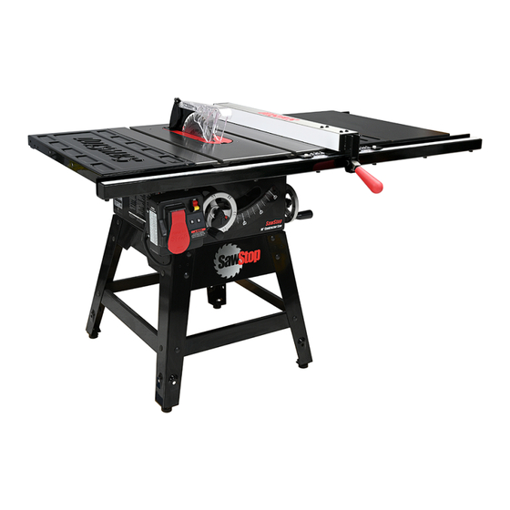
- Page 2 The saw on the front cover is shown with fence model TSA-PFA. Your saw may look different. SawStop, the SawStop blade logo, and the configuration of this product are either registered trademarks or trademarks of SawStop, LLC. Software copyright by SawStop, LLC. All rights reserved. Protected by the following U.S.
- Page 3 ® Contractor Saw. We are confident you will be pleased with its performance. If you ever have any questions or comments, feel free to contact us at the address below. SawStop, LLC 11555 SW Myslony Street Tualatin, Oregon 97062 USA SawStop.com...
-
Page 4: Table Of Contents
Warranty No Warranty of Safety If You Have an Accident Safety Warnings Warning Labels ® The SawStop Safety System Unpacking Your Saw Assembling Your Saw Assembling the Stand Mounting the Saw to the Stand Installing the Elevation Hand-wheel Installing the Tilt Hand-wheel... - Page 5 SawStop Brake Cartridge Changing the Brake Cartridge Installing a Brake Cartridge ® What to do if the SawStop Safety System Activates Making Adjustments to Your Saw Adjusting the Elevation Limit Stops Adjusting the Tilt Limit Stops and Tilt Angle Indicator...
- Page 6 TABLE OF CONTENTS Troubleshooting Contractor Saw Specifications Contractor Saw Dimensions Push Stick Construction Auxiliary Fence Construction Push Block Construction Featherboard Construction Accessories Index SawStop 10” Contractor Saw ®...
-
Page 7: Warranty
This warranty is void if the saw or any portion of the saw is modified without the prior written permission of SawStop, LLC, or if the saw is located or has been operated outside of the country where the authorized SawStop distributor from whom the saw was purchased resides. -
Page 8: Safety
The smaller the gauge number the heavier the cord. The Contractor Saw in its standard configuration is intended for use on a 110-120V supply circuit that has an outlet that looks like the one illustrated in Sketch A below. SawStop 10” Contractor Saw ®... - Page 9 Sketch D SawStop 10” Contractor Saw ®...
- Page 10 Pay particular attention to instructions on reducing the risk of kickback. Kickback occurs when a work piece contacts the downstream edge of the blade as it is being cut and is propelled back towards the user at high velocity. SawStop 10” Contractor Saw ®...
- Page 11 Use only recommended accessories with the saw. Consult this manual for recommended accessories. The use of improper accessories may cause risk of injury. When servicing, use only identical replacement parts. Keep the top of the saw clean and free from clutter. Cluttered areas invite accidents. SawStop 10” Contractor Saw ®...
-
Page 12: Warning Labels
Copies of some of the English text of the warning labels are reproduced below: WARNING WARNING To avoid loss of SawStop protection during coast down, do not turn off Main Power until blade has stopped spinning. -
Page 13: The Sawstop ® Safety System
This Contractor Saw is equipped with the SawStop® safety system. This revolutionary technology was developed to reduce the potential for a serious injury in the event of accidental contact with the saw blade. SawStop® saws are the only saws smart enough to know the difference between you and the wood you are cutting. - Page 14 ® The SawStop® safety system does not interfere with your use of the saw. You can still make all the cuts that you can with ordinary saws including 0° to 45° bevels, non-through cuts, and dado cuts (with the optional dado brake cartridge and the optional dado table insert).
- Page 15 SawStop saw as the combined weight of the blades may be too heavy to stop quickly. If you need to use a blade with a kerf thicker than 3⁄16 inch, use an 8 inch dado set with the optional Sawstop 8 inch dado brake cartridge.
-
Page 16: Unpacking Your Saw
Front Panel Short Brackets Legs Rear Panel Long Brackets Switch Box Extension Wings (With pre-installed 10” saw blade, (Connected to the saw zero-clearance table insert, brake by an electric cable) cartridge, and brake cartridge key) SawStop 10” Contractor Saw ®... - Page 17 Blade Guard Elevation Handwheel Tilt Handwheel Assembly Package Package Miter Gauge Riving Knife Blade Wrenches (pre-installed) (two) SawStop ® 10” CONTRACTOR SAW OWNER’S MANUAL Assembly Instructions Poster Hardware Pack #1 Hardware Pack #2 Owner’s Manual SawStop 10” Contractor Saw ®...
-
Page 18: Assembling Your Saw
Attach the legs to the rear panel using four M8 x 20 carriage bolts, four M8 washers, four M8 lock washers, and four M8 hex nuts. Do not fully tighten the nuts at this time. SawStop 10” Contractor Saw ®... - Page 19 Use two M8 x 20 carriage bolts, two M8 washers, two M8 lock washers, and two M8 hex nuts. Do not fully tighten the nuts. Repeat this process to attach the remaining short bracket between the rear legs. SawStop 10” Contractor Saw ®...
- Page 20 There is one hole in each corner of the stand (see Fig. 10). Adjust the panels until the holes align and then tighten all of the nuts in the stand using a 13 mm wrench. Fig. 10 Mounting holes SawStop 10” Contractor Saw ®...
-
Page 21: Mounting The Saw To The Stand
M8 washer and thread a second M8 hex nut onto each foot. Do not fully tighten the nuts. The stand is now fully assembled. SawStop Note: If you purchased an optional ®... - Page 22 14). Make sure to place a washer between the screw head and the saw and to place a washer and lock washer above each nut with the lock washer next to the nut, as shown. Fully tighten all of the nuts using two 13 mm wrenches. Fig. 14 a la lluvi SawStop 10” Contractor Saw ®...
- Page 23 Volts, idad / Électric 1 Phase Amps 60 Hz ité 3500 1.75 SawStop, ® www.sa wstop.c 175370 Made in Taiwan Fig. 16 14. Place a level across the table top and adjust the four feet of Level the table top the stand by turning the lower hex nuts until the table top is level (you may need to loosen the upper hex nuts).
-
Page 24: Installing The Elevation Hand-Wheel
16. Open the blade tilt package and slide the hand-wheel onto the tilt control shaft and then thread the tilt lock knob onto the shaft (see Fig. 18). Fig. 18 Hand-wheel Tilt control shaft Tilt lock knob SawStop 10” Contractor Saw ®... -
Page 25: Installing The Motor And Belt Guard
Saw Model No. CNS 175 Serial No. C074012345 Electrical / Electricidad / Électricité 115/230 Volts, 60 Hz 1.75 HP 15/7.5 Amps 3450 RPM 1 Phase ® 175370 SawStop, LLC www.sawstop.com Made in Taiwan SawStop 10” Contractor Saw ®... -
Page 26: Mounting The Extension Wings
(see Fig. 23). It doesn’t matter which direction the SawStop lettering on the top of the extension wing faces. Mount the left extension wing with four M8 lock washers and four M8 x 16 hex screws, but do not tighten. Repeat the same procedure to mount the other extension wing to the right side of the table. -
Page 27: Mounting The Switch Box
¯ CONGRATULATIONS, YOUR SAW IS NOW ASSEMBLED. Note: You must install a rip fence prior to using the saw. Refer to the manual accompanying your rip fence for instructions on how to install the fence. SawStop 10” Contractor Saw ®... -
Page 28: Get To Know Your Saw
10. Miter Gauge Slots 11. Spreader / Riving Knife Storage Pins (2) Fig. 27 12. Blade Wrenches (2) 13. Riving Knife 14. Tilt Angle Indicator 15. Tilt Angle Scale 16. Stand 17. Thermal Overload Switch 18. Push Stick SawStop 10” Contractor Saw ®... - Page 29 30. Arbor Washer 37. Cartridge Key 24. Elevation Plate 31. Dust Shroud 38. Quick-Release Clamp Handle 25. Motor 32. Dust Port 39. Riving Knife 26. Motor Belt 33. Upper Elevation Limit Stop 40. Saw Blade Fig. 29 SawStop 10” Contractor Saw ®...
-
Page 30: Preparing Your Saw For Use
WARNING! Never operate the saw without the table insert in place. CAUTION! Do not use table inserts with metal or other electrically-conductive parts that could contact the blade. This can cause the brake to be activated unnecessarily. SawStop 10” Contractor Saw ®... -
Page 31: Blade Or Dado Installation
You can use a dado set to cut a groove or slot in a workpiece. Other sizes or types of blades are not compatible with a SawStop saw. -
Page 32: Brake Position Adjustment
Adjust the brake position as brake needed to set the spacing between the teeth of the blade and positioning the closest point on the brake cartridge to between 1⁄16 and bolt see Fig. 34 3⁄32 inch ( SawStop 10” Contractor Saw ®... - Page 33 Fig. to verify that the blade does not hit the brake ( spin the blade by hand to make sure the blade does not touch the brake SawStop 10” Contractor Saw ®...
-
Page 34: Blade Guard And Riving Knife Installation
Blade Guard and Riving Knife Installation Your SawStop® saw includes a unique, quick-release blade guard mounting system. This mounting system was developed to allow you to quickly remove and install the blade guard and riving knife without the use of tools and without the need for realignment. - Page 35 Note: when using a dado set, neither the blade guard nor the riving knife may be used. Instead, use other see page 54; see Fig. 106 Fig. protective devices such as push sticks, push blocks and featherboards ( Fig. 109 SawStop 10” Contractor Saw ®...
-
Page 36: Dust Collection
SawStop recommends the use of a dust collection system that provides at least 350 CFM of flow at the dust port. Attach a 4 inch diameter flexible hose between the inlet port on your dust collector and the port on the dust shroud (see Fig. -
Page 37: Electrical Power Connection
Do not use any other motor to power your saw. Connect the saw to an electrical circuit that is protected by a 20 amp breaker. Note: The A-C motor that comes with Contractor Saw model CNS175-AU (sold in Australia) is pre-wired for 208- 240V power and operates at 50 Hz. The contactor box assembly that comes with CNS175-AU is designed for 240V / 50Hz power. -
Page 38: Re-Wiring The Saw For 208-240V Power
WA-014). The contactor box assembly that comes with your saw is only rated for 110-120V power and it is not compatible with the motor in the 208-240V configuration. To use 208-240V power, you must purchase a SawStop 230V contactor box assembly. -
Page 39: Electrical Schematic
Junction Box on Motor wire nut WARNING! re-wire motor for 208-240V power until you have installed a 230V contactor box white assembly (CNS-WA-014). wire nut wire nut black motor yellow white green black from switch switch 208-240 V SawStop 10” Contractor Saw ®... -
Page 40: Changing The Plug Or Power Cord On A 208-240V Saw
WARNING! Make sure the saw is unplugged from the wall outlet before proceeding with the following instructions. Locate the contactor box which is mounted to the back side of see Fig. 44 the switch box bracket ( contactor box SawStop 10” Contractor Saw ®... - Page 41 Fig. 42 Fig. 43 removing the end of the green power cord wire from the ground connection ( Fig. 46 Fig. 47 Ground Contactor Power cord SawStop 10” Contractor Saw ®...
- Page 42 Fig. 49 in Fig. ). A wiring diagram is shown BREAKER GROUND Green White Black Fig. 49 Ground Thermal circuit breaker CONTACTOR COIL COIL Contactor Green Power cable CONTACTOR POWER MOTOR SWITCH BOX CABLE CABLE CABLE SawStop 10” Contractor Saw ®...
-
Page 43: Using Your Saw
0° and 45° Tilt lock knob set points. These limit stops are pre-set at the factory and should not need adjustment. If you decide to adjust the blade tilt limit stops, page 65 for instructions. SawStop 10” Contractor Saw ®... -
Page 44: Turning On Main Power And Starting The Motor
Turning on the Main Power and Starting the Motor Your SawStop® saw is equipped with a main power switch to supply power to the SawStop® safety system and a Start/Stop paddle to turn the motor on and off. Both the main power switch and the Start/Stop paddle are mounted on the switch box ( see Fig. - Page 45 An audible click will indicate that the thermal overload switch has been reset and the saw is ready to use. Double check the electrical circuit and all electrical connections and always use an appropriate feed rate for the material that you are cutting. SawStop 10” Contractor Saw ®...
-
Page 46: System Status Codes
A description of each status code and the necessary corrective action is provided on the following pages. Fig. 56 SawStop System Status Codes Symbol Key Status... - Page 47 Standby Mode. The brake will not be activated and the code will automatically clear within 5 seconds after contact is ended. The system will not allow the motor to start while this code is displayed. SawStop 10” Contractor Saw ®...
- Page 48 The overload error indicates that the system was close to firing the brake before it went into overload. Therefore, repeatedly attempting to cut a wet piece of wood could result in an unnecessary activation of the brake. SawStop 10” Contractor Saw...
-
Page 49: Using The Blade Guard
The blade guard on your SawStop® saw was designed to have a narrow profile that allows you to use the guard even when making narrow rip cuts. - Page 50 When not in use, the blade guard can be stored by hanging it on one of the storage pins on the left side of the saw ( Fig. 64 SawStop 10” Contractor Saw ®...
-
Page 51: Using The Riving Knife
Positioning the miter gauge in the left slot when making bevel cuts causes the blade to be tilted toward the miter gauge and the operator’s hand which could result in a serious injury. SawStop 10” Contractor Saw ®... - Page 52 Do not touch the portion of the workpiece that was cut off until the blade stopped. WARNING! Never make free-hand cuts. Never hold or touch an unsupported piece of wood while the blade is spinning. SawStop 10” Contractor Saw ®...
-
Page 53: Cross-Cutting
WARNING! To reduce the potential for kickback and a serious injury, move the rip fence out of contact with the workpiece when cross-cutting to prevent the workpiece from binding between the rip fence and the blade. SawStop 10” Contractor Saw ®... -
Page 54: Using A Fence
The system also includes steel front and rear rails, a steel clamp tube, and SawStop’s proprietary design that makes the fence slide smoothly. This fence system can be used with optional 36 or 52 inch extension tables. -
Page 55: Rip Cutting
See page 81 for instructions on making a push stick.) WARNING! To reduce the chance of a serious injury, always use a push stick or push block when your hand comes within 6 inches of the blade. SawStop 10” Contractor Saw ®... - Page 56 ). Although not shown in the illustration, a second featherboard can be clamped to the top of the table and against the left side of the workpiece to hold the workpiece against the rip fence. SawStop 10” Contractor Saw ®...
-
Page 57: Using The Saw In Bypass Mode
If that occurs and the saw is started, then the shard could contact the aluminum brake pawl and cause the brake to activate. SawStop 10” Contractor Saw ®... -
Page 58: Using A Mobile Base
For example, you may want to store the stationary saw against a wall in your workshop and then move it away from the wall to use it. SawStop offers an optional mobile base that allows you to reposition your stationary saw with ease. -
Page 59: The Sawstop® Brake Cartridge
THE SAWSTOP BRAKE CARTRIDGE ® The SawStop® brake cartridge ( see Fig. 76 Fig. 76 includes a sealed housing containing the ® system electronics, and an aluminum SawStop Brake pawl block called a brake pawl. The sealed housing also includes a high-... -
Page 60: Changing The Brake Cartridge
THE SAWSTOP BRAKE CARTRIDGE ® Changing the Brake Cartridge Changing the brake cartridge is both simple and foolproof. The safety system will not allow the motor to start unless the brake cartridge is correctly installed. Before changing the brake cartridge, make sure the Start/Stop paddle is pushed in to the OFF position, the main power switch is toggled down to the OFF position, and the power cord is unplugged. - Page 61 THE SAWSTOP BRAKE CARTRIDGE ® Pivot pin Fig. 79 The brake cartridge is mounted on a large pivot pin and a smaller positioning pin ( see Fig. 79 ). Both the pivot pin and positioning pin extend outward from a cartridge mounting bracket that sets the position of the cartridge.
- Page 62 THE SAWSTOP BRAKE CARTRIDGE ® Fig. 81 If the brake cartridge has not been activated, slide the brake cartridge to the right until it clears both pins ( Fig. 81 If the cartridge has been activated, the brake pawl typically will be locked onto the blade or dado set. As a result, it is usually easiest to remove the blade and the brake cartridge together.
-
Page 63: Installing A Brake Cartridge
THE SAWSTOP BRAKE CARTRIDGE ® Installing a Brake Cartridge WARNING! Always turn off the main power switch and unplug the power cord before removing or installing the brake cartridge on your saw. To install a brake cartridge, the above process is reversed. Align the mounting holes in the cartridge with the pivot pin and positioning pin in the saw. -
Page 64: What To Do If The Sawstop ® Safety System Activates
If you are unsure why the cartridge activated, you can return the cartridge to SawStop for analysis by SawStop’s service engineers. When the cartridge data is downloaded, it is usually possible to determine what caused the brake to activate so that further unintended activations can be prevented. -
Page 65: Making Adjustments To Your Saw
Once the blade is set to the correct maximum elevation, turn the set screw clockwise until it is tight. The upper elevation limit has now been set. Upper elevation limit stop SawStop 10” Contractor Saw ®... - Page 66 M6 hex nut against the rear trunnion. The lower elevation limit has now been set. Rubber bumper SawStop 10” Contractor Saw ®...
-
Page 67: Adjusting The Tilt Limit Stops And Tilt Angle Indicator
Next, adjust the tilt hand-wheel limit stop until the blade is at 90° to the table. Turn the 0° limit set screw clockwise until it is tight. The 0° limit stop has now been set. 45° tilt limit stop SawStop 10” Contractor Saw ®... - Page 68 If necessary adjust the indicator by loosening the Locking screw locking screw with the included 5 mm hex key and rotating the indicator until it reads 0°. Lock the indicator in place by tightening the locking screw. Tilt angle indicator SawStop 10” Contractor Saw ®...
-
Page 69: Adjusting The Table Insert
Adjusting the Table Insert ® The SawStop zero-clearance insert has been designed to fit securely within the table opening and just below the table top. The blade slot in the insert is pre-cut at the factory after all alignments to the saw have been completed. - Page 70 The height of the lock down screws can be adjusted using the included 3 mm hex key. Fig. 94 Table lock down Rear Rear screws leveling leveling screw screw SawStop 10” Contractor Saw ®...
-
Page 71: Aligning The Riving Knife And Spreader To The Blade
(using an 8 mm hex key) just enough so that you can slide the clamp along its mounting surface with some friction. Reinstall the blade and raise the blade to the fully Mounting elevated position. bolts SawStop 10” Contractor Saw ®... -
Page 72: Adjusting The Height Of The Riving Knife
This allows the riving knife to be used on rabbet cuts and other non-through cuts. WARNING! Always turn off the main power switch and unplug the power cord before making any adjustments to your saw. SawStop 10” Contractor Saw ®... - Page 73 4-8 mm. Once the clamp has been properly positioned, further adjustment should not be necessary. Both the spreader and riving knife will now automatically align when installed in the clamp. SawStop 10” Contractor Saw ®...
-
Page 74: Adjusting The Quick-Release Clamp
If the pressure is too low these important safety devices may not function properly and a serious injury could result. In addition, the spreader or riving knife may come into contact with the blade and cause an unintended activation of the safety system. SawStop 10” Contractor Saw ®... -
Page 75: Adjusting The Miter Gauge
Finally, tighten the hex nut against the indexing stop flange to prevent the screw from moving. Repeat the above process for the other indexing stops if desired. stop adjustment indexing screw SawStop 10” Contractor Saw ®... -
Page 76: Maintenance
WARNING! Always turn off the main power switch and unplug the power cord before doing any maintenance on your saw. The SawStop Safety System The safety system performs continuous self-checks both before and during saw operation. If a problem is detected, the appropriate status code will be displayed on the LEDs on the switch box and the appropriate action should be taken. -
Page 77: Troubleshooting
Codes to determine the cause of the Bypass Mode. error code on the LEDs. error and the corrective action. 3. The Bypass key is not fully seated. 3. Insert the Bypass Key fully and ensure °. it turns a full 90 SawStop 10” Contractor Saw ®... - Page 78 4. The voltage supplied to the motor is 4. Ensure the motor is wired to match incorrect. the power that is being supplied. If using an extension cord, ensure the extension cord is the correct gauge. SawStop 10” Contractor Saw ®...
- Page 79 1. Ensure the motor is wired to match The motor starts slowly and/or incorrect. the power that is being supplied. If fails to reach nominal speed. using an extension cord, ensure the extension cord is the correct gauge. SawStop 10” Contractor Saw ®...
-
Page 80: Contractor Saw Specifications
Motor Options: 1.75 hp, 60 Hz, dual voltage motor (model CNS175) 14A at 110-120V (pre-wired in this configuration) or 7A at 208-240V 1.75 hp, 50 Hz, 208-240V (model CNS175-AU) 1.75 hp, 50 Hz, 220V (model CNS175-CH) SawStop 10” Contractor Saw... -
Page 81: Contractor Saw Dimensions
Fig. 104 SawStop 10” Contractor Saw ®... - Page 82 Fig. 105 SawStop 10” Contractor Saw ®...
-
Page 83: Push Stick Construction
Fig. 106 SawStop 10” Contractor Saw ®... -
Page 84: Auxiliary Fence Construction
Fig. 107 SawStop 10” Contractor Saw ®... -
Page 85: Push Block Construction
Fig. 108 SawStop 10” Contractor Saw ®... -
Page 86: Featherboard Construction
Fig. 109 SawStop 10” Contractor Saw ®... -
Page 87: Accessories
ACCESSORIES SawStop recommends the following accessories for use with your SawStop ® Contractor Saw. Contact your local authorized SawStop Dealer or SawStop at 1-866-SAWSTOP for more information. SawStop Brake Cartridges: Standard Brake Cartridge for 10 inch saw blades TSBC-10R2 or... -
Page 88: Index
15, 26, 29, 60 Blade Guard anti-kickback pawl: 47–48, 54, 70 guard: 8, 12, 15, 26, 32–33, 47–48, 53, 78 installation: 32–33 spreader: 8, 26, 32–33, 47–47, 54, 69–71, 72, 75, 76, 77, 78 using: 47–48 SawStop 10” Contractor Saw ®... - Page 89 29, 85 set: 12–13, 28, 29, 33, 57, 60, 61, 77, 78, 85 Depth of Cut: 50, 78 Detection of Accidental Contact: 1, 5, 11–13, 42, 44–46, 62 Dimensions: 79–80 Dust collection: hazard: 6, 34 SawStop 10” Contractor Saw ®...
- Page 90 Get to Know Your Saw: 26–27 Green Wood: 46, 75 Guard (see Blade Guard) Hand-wheel(s): 15, 22, 26, 41, 77, 78 Insert (see Table Insert) Kerf: 13, 29, 49, 69–70, 78 Kickback: 32, 47–48, 51, 54 SawStop 10” Contractor Saw ®...
- Page 91 ™ Push Block: 33, 53–54, 83 Push Stick: 8, 12, 26, 33, 53–54, 81 Quick-Release Clamp: 27 ,32, 33, 69–70, 72, 76 Rear Trunnion: 27, 36, 64 Rear Trunnion Bracket: Retraction: 11, 13, 34, 62 SawStop 10” Contractor Saw ®...
- Page 92 32–33 using: 26, 27, 47, 49, 75, 76, 77 Safety: 6–9, 11–13 Saw Placement: SawStop Safety System activation: 12–13, 46, 57, 60, 62, 64, 70, 72, 75 Bypass Mode: 5, 11–13, 44–46, 55, 75 system status codes(s): 42, 44–46, 55, 61, 62, 74, 75 ScotchBrite ®...
- Page 93 Using Your Saw: 41–57 Warning Labels: Warranty: 1, 5, 13, 35 WD-40 ® Wet Wood: 13, 44, 46, 75 Wiring (see Electrical, power connection and schematics) Wood Stop: Worm Gear: Zero-Clearance Table Insert (see Table Inserts) SawStop 10” Contractor Saw ®...
- Page 94 NOTES SawStop 10” Contractor Saw ®...
- Page 95 NOTES SawStop 10” Contractor Saw ®...
- Page 96 SawStop, LLC 11555 SW Myslony Street Tualatin, Oregon 97062 USA SawStop.com Technical Support 503-582-9934 service@sawstop.com Parts Store 503-486-6923 parts@sawstop.com Sales / Customer Service 503-595-2665 sales@sawstop.com p/n 85-000424-00 Rev C - July 2024...
Need help?
Do you have a question about the CNS175-AU and is the answer not in the manual?
Questions and answers