Advertisement
Quick Links
Advertisement

Related Manuals for SawStop CNS-SFA


Summary of Contents for SawStop CNS-SFA
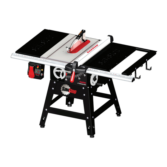
- Page 1 SawStop ® Contractor Fence Assembly OWNER’S MANUAL Model CNS-SFA...
-
Page 2: Warranty
SawStop will, upon proof of purchase and at its expense, send replacement parts to the original retail purchaser necessary to cure the defect. Alternatively, SawStop will repair the fence assembly provided it is returned to SawStop, shipping prepaid, within the warranty period. - Page 3 If you are missing hardware pack #3 or any of the other fence assembly components, call the SawStop Service Department at 503-682-6222 for replacements. Hardware Pack...
- Page 4 If you are missing hardware pack #3 or any of the other fence Square Head Screws, M8 x 20 (10 + 1 extra) assembly components, call the SawStop Service Department at 503-582-9934 for replacements. Lock Washers, M8...
- Page 5 M8 x 16 hex screws, three M8 lock washers, and one M8 hex nut (see Fig. 6). Hand tighten the hex screws; do not fully tighten them. The right rear rail should extend beyond the right extension wing. Fig. 6 SawStop Contractor Fence Assembly...
- Page 6 Do not tighten the hardware that mounts the material support shelf to the front rail. SawStop 10” Contractor Saw Fig. 9 SawStop Contractor Fence Assembly...
- Page 7 Fig. 11 12. Locate the fence and red fence handle. Thread the handle into the cam lock on the front of the fence (see Fig. 12). thread the handle into the cam lock Fig. 12 SawStop Contractor Fence Assembly...
- Page 8 14. To determine the final placement of the front rail, raise the saw blade and position the fence so that the left side of the fence rests against the right side of the saw blade (see Fig. 14). Fig. 14 SawStop Contractor Fence Assembly...
- Page 9 Fig. 16 Congratulations, your fence assembly is now installed and your saw is ready to use. SawStop Contractor Fence Assembly...
- Page 10 Once the left indicator right indicator fence is in the correct position, push the red locking handle down to the locked position. The fence is now locked in place and ready for use. Fig. 19 SawStop Contractor Fence Assembly...
- Page 11 5 mm hex key (see Fig. 21). Then align the side of the fence with the miter slot, clamp the fence in place and re-tighten the screws. The fence is now set parallel to the cutting surface of the blade. Fig. 21 SawStop Contractor Fence Assembly...
- Page 12 Contractor Fence Rails Assembly Exploded View SawStop Contractor Fence Assembly...
- Page 13 SFA-07-009 M8x1.25x16 Hex Screw SFA-07-010 Material Support Shelf SFA-07-011 Large Storage Hook SFA-07-012 M8x1.25x20 Carriage Bolt SFA-07-013 Small Storage Hook SFA-07-014 Accessories Contractor Fence Assembly Owner’s Manual SFA-07-046 Installation Instructions Poster SFA-07-047 Hardware Pack #3 SFA-07-048 SawStop Contractor Fence Assembly...
- Page 14 Contractor Fence Assembly Exploded View SawStop SawStop Contractor Fence Assembly...
- Page 15 Clamp Release Spring SFA-07-038 Clamp Adjustment Nut SFA-07-039 M4.3x12x1 Washer SFA-07-040 M4x0.7x10 Button Head Philips Screw SFA-07-041 Fence End Cap SFA-07-042 M6x40 Spring Pin SFA-07-043 M4x16 Button Head Philips Sheet Metal Screw SFA-07-044 Fence Label SFA-07-045 SawStop Contractor Fence Assembly...
- Page 16 9564 S.W. Tualatin Road Tualatin, Oregon 97062 www.sawstop.com Main Phone - (503) 570-3200 Service - (503) 582-9934 Fax - (503) 570-3303 Email: info@sawstop.com Updates of this manual may be available at www.sawstop.com. Copyright SawStop, LLC All Rights Reserved. June 2014...
Need help?
Do you have a question about the CNS-SFA and is the answer not in the manual?
Questions and answers