
Related Manuals for Carrier Access Wide Bank 28 DS3


Summary of Contents for Carrier Access Wide Bank 28 DS3
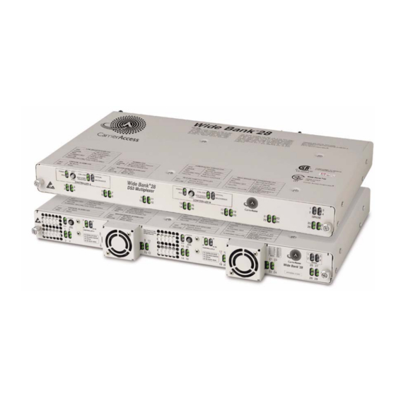
- Page 1 Wide Bank 28 DS3 ANUAL Fan Faceplate Option (FFO) Document: 770-0074-AT Product Release: 2.4 July 2004...
- Page 2 The information presented in this manual is subject to change without notice and does not represent a commitment on the part of Carrier Access Corporation. The hardware and software described herein are furnished under a license or non-disclosure agreement. The hardware, software, and manual may be used or copied only in accordance with the terms of this agreement.
- Page 3 REFACE Preface In this Preface Compliance ... iv Safety Precautions ... vi Notices ... vi Electrostatic Discharge Guidelines ... vii Warranty ... viii...
-
Page 4: Compliance
The telephone company may make changes in its facilities, equipment operations, or procedures that could effect the operation of the Wide Bank 28 DS3. If this occurs, the telephone company will provide advance notice so that you may make necessary modifications to maintain uninterrupted service. -
Page 5: Safety Requirements For Telecommunications Equipment
If the trouble is causing harm to the telephone network, the telephone company may request that you remove the Wide Bank 28 DS3 from the network until the problem is resolved. User repairs must not be made. Doing so will void your warranty. -
Page 6: Japan Approvals Institute For Telecommunication Equipment (Jate)
Refer to the installation chapters of this manual for safe and proper installation procedures. Notices This manual contains information and warnings that must be followed to ensure safe conditions for personnel while operating or maintaining the Wide Bank 28 DS3. Safety labels and notes have the following format and definitions: DANGER! -
Page 7: Electrostatic Discharge Guidelines
The ESD warning label below appears on packages and storage bags that contain static-sensitive products and components. Static electricity is always present, and using general anti-static procedures will minimize the chances of damage to the Wide Bank. Wide Bank 28 DS3 - Release 2.4 July 2004... -
Page 8: Warranty
Carrier Access. An exception is the Battery Unit product, which is warranted for 90 days. -
Page 9: Warranty Product Returns
No agent, Distributor, or representative is authorized to make any warranties on behalf of Carrier Access or to assume for Carrier Access any other liability in connection with any of Carrier Access’s Products, software, or services. Warranty Product Returns Before returning any equipment to Carrier Access Corporation, first contact the distributor or dealer from which you purchased the product. - Page 10 July 2004 Wide Bank 28 DS3 - Release 2.4...
-
Page 11: Table Of Contents
Wide Bank 28 DS3 Features........ - Page 12 LS Alarm Signals ........... . . 2-32 July 2004 Wide Bank 28 DS3 - Release 2.4...
- Page 13 Mounting the Wide Bank 28 DS3 ........
- Page 14 Show Current User Settings (Basic Security) ....... . 6-9 July 2004 Wide Bank 28 DS3 - Release 2.4...
- Page 15 Downloading to a Redundant Wide Bank 28 DS3 ....... .
- Page 16 DS3 Payload Loopback with C-bit Framing ....... . 7-36 July 2004 Wide Bank 28 DS3 - Release 2.4...
- Page 17 DS1 ENABLE/DISABLE ..........8-23 Wide Bank 28 DS3 - Release 2.4...
- Page 18 LS ENABLE/DISABLE ........... 8-53 xviii July 2004 Wide Bank 28 DS3 - Release 2.4...
- Page 19 VERSION ............. . 8-85 Wide Bank 28 DS3 - Release 2.4...
- Page 20 Error Message in Response to Commands Not Recognized or Supported ... . . 9-16 Error Response to Valid Commands Received When a User Is Not Logged In ..9-16 July 2004 Wide Bank 28 DS3 - Release 2.4...
- Page 21 RTRV-<FacilityType> ........... . . 9-47 Wide Bank 28 DS3 - Release 2.4...
- Page 22 Date <date> ............. 9-89 xxii July 2004 Wide Bank 28 DS3 - Release 2.4...
- Page 23 User Identifier <uid> ........... . . 9-100 Wide Bank 28 DS3 - Release 2.4...
- Page 24 Carrier Access DS3 Multiplexer Enterprise MIBs ........
- Page 25 RJ-45 Connector ............A-9 Glossary Index Wide Bank 28 DS3 - Release 2.4 July 2004...
- Page 26 Table of Contents xxvi July 2004 Wide Bank 28 DS3 - Release 2.4...
- Page 27 HAPTER 9Introduction In this Chapter System Overview ... 1-2 Features, Functions, and Options ... 1-3 Wide Bank 28 DS3 Features ... 1-3 DS3 Ports ... 1-4 DS1 and E1 Ports ... 1-4 Independent Clocking and Transparent Framing ... 1-4 Manageability ...
-
Page 28: Introduction
System Overview Fan Faceplate Option (FFO) Carrier Access’ Wide Bank 28 DS3 Multiplexer provides a standards-based M1-3 multiplexing function. This product converts a framed Digital Signal Level 3 (DS3) network connection to 28 Digital Signal Level 1 (DS1) connections to T1 facilities, or 21 connections to E1 facilities. -
Page 29: Features, Functions, And Options
DS3 C-bit application for Far-End terminal alarming, status reporting, and remote loopback initiation DS3 C-bit application terminal-to-terminal data link for identification message support and management of the remote terminal using Telnet, SNMP, or TL1 over PPP Wide Bank 28 DS3 - Release 2.4 July 2004... -
Page 30: Ds3 Ports
Because of independent timing and transparent framing, the installation and maintenance of the DS1 or E1 connections are easily managed. Because the Wide Bank 28 DS3 transmits DS1 or E1 streams transparently into a DS3 composite, there are no framing or timing options to set on the 28 DS1 or 21 E1 connections. -
Page 31: Manageability
Security To control access to user interface functions, the Wide Bank 28 DS3 Multiplexer supports a multiple-level user security system. Basic security, which allows users to be assigned access levels and passwords, is supported by all Wide Banks. Enhanced security, available as the “Security Upgrade”... -
Page 32: Security Upgrade Option
Wide Bank that supports the numerical access levels, the Level 1 user is automatically converted to secu; Level 2 users are converted to rw; and Level 3 users are converted to ro. July 2004 Wide Bank 28 DS3 - Release 2.4... -
Page 33: Management Capabilities
When security is off, no password is required, and each user is considered to be at the secu level. Management Capabilities The Wide Bank 28 DS3 currently provides three management ports for full configuration and monitoring. These ports are: One 9-pin RS-232 port for local Command Line Interface (CLI) control... -
Page 34: Command Line Interface
IP address to the Wide Bank using the RS-232 interface SNMP The Wide Bank 28 DS3 contains an embedded SNMP v1 agent that offers the standard MIB II (RFC 1213) in addition to the DS1/E1 MIB (RFC 1406) and the DS3 MIB (RFC 1407). -
Page 35: Networkvalet Software
NetworkValet sends commands over the carrier’s IP network to communicate with the SNMP agent in the Wide Bank 28 DS3. The Wide Bank includes a standard 10Base-T Ethernet port for connection to the hub or network interface, or laptop computer. The Wide Bank 28 DS3 must have FLASH software version 2.00 or higher. - Page 36 Introduction Management Capabilities 1-10 July 2004 Wide Bank 28 DS3 - Release 2.4...
- Page 37 HAPTER 9Product Description In this Chapter Overview ... 2-2 Physical Characteristics ... 2-5 Connector Panel Interfaces ... 2-6 Framing Modes ... 2-8 LED Test and Status Indicators ... 2-14 Controller and DS3 Redundancy ... 2-17 Low-Speed (LS) Redundancy ... 2-22 Tests and Loopbacks ...
-
Page 38: Product Description
Redundant Architecture ... 2-4 The Wide Bank 28 DS3 Multiplexer is available in increments up to the maximum of seven four- channel DS1 cards supporting 28 DS1 connections, or with seven three-channel E1 cards supporting 21 E1 connections. Built-in options include 1:7 low-speed electronic redundancy, 1:1 Controller electronics redundancy and electronics redundancy with 1+1 network protection. - Page 39 Automatic monitoring for fan presence and fan failure, fault-tolerant fan redundancy, and in- service hot swapping of FFO assembly in less than 30 seconds eliminates traditional fan maintenance concerns Wide Bank 28 DS3 - Release 2.4 July 2004...
-
Page 40: Redundant Architecture
Overview Redundant Architecture The Wide Bank 28 DS3 multiplexer uses two DS3 processors, which handle the DS3 interfaces, and a backplane bus that accesses the low-speed interfaces. It also contains up to seven active low-speed circuit boards and one optional spare circuit board that connect to the low-speed interfaces. -
Page 41: Physical Characteristics
0.875" Front cover is removable (See Chapter 10) All cards are removed Rack and wall-mounting from front of unit holes (See Chassis Mounting (See Chapter 10) in Chapter 4) Wide Bank 28 DS3 - Release 2.4 July 2004... -
Page 42: Connector Panel Interfaces
DS3 Connectors. There are four DS3 connections: Primary (Active) in and out, and Secondary (Protection) in and out, which make up two DS3 ports. Each Controller card has a single DS3 interface, so the Wide Bank 28 DS3 must have two Controller cards installed to have two DS3 ports available. - Page 43 The contacts can be programmed to be normally open or normally closed. One cable connector, which can be wired to externally-powered alarm monitor or indicator, is provided with each Wide Bank 28 DS3. For wiring information, see External Alarm Wiring on page 5-12.
-
Page 44: Framing Modes
DS3 Multiframe Structure ... 2-9 The Wide Bank 28 DS3 can be configured for either M23 or C-bit framing. The major difference between M23 framing and C-bit parity framing is that M23 framing uses the C-bits to indicate stuffing, while C-bit parity framing does not. -
Page 45: Ds3 Multiframe Structure
Figure 2-2 shows how the frame is structured with the C-bits highlighted. Figures 2-5 through 2-8 provide details about the individual subframes. M Subframe = 680 bits M Frame = 4760 bits Figure 2-2 Multiframe Structure Wide Bank 28 DS3 - Release 2.4 July 2004... -
Page 46: X-Bits - Error Message From Far-End To Near-End
M Subframe No. 1 Indicates Framing Sends Alarm/Status Information from Reserved Network Far-End Terminal back to Near-End Mode of the Equipment Application Bit (1 = C-bit parity) Terminal Figure 2-3 Subframe 1 C-bits 2-10 July 2004 Wide Bank 28 DS3 - Release 2.4... -
Page 47: Far End Alarm (Fea) Bit
FEBE bits are set to any combination of 1s and 0s except 111, and sent to the far-end terminal. A setting of 111 means there are no framing or parity errors. See Figure 2-5. Wide Bank 28 DS3 - Release 2.4 July 2004... - Page 48 M Frame (4760 bits) Subframe Subframe Subframe Subframe Subframe Subframe Subframe Bits Bits M Subframe No. 4 P-Bit Support the Far-End (Parity) Block Error (FEBE) function Figure 2-5 Subframe 4 C-bits 2-12 July 2004 Wide Bank 28 DS3 - Release 2.4...
-
Page 49: Dlt Bits
M Frame (4760 bits) Subframe Subframe Subframe Subframe Subframe Subframe Subframe Bits Bits M Subframe No. 5 Transmit path identification number over path-maintenance data link in point-to-point application Figure 2-6 Subframe 5 C-bits Wide Bank 28 DS3 - Release 2.4 July 2004 2-13... -
Page 50: Led Test And Status Indicators
GREEN ETHERNET STATUS 5V Onboard Power (On Rear Panel) Supply Failed LED State Meaning No Power or No Link GREEN Link OK Figure 2-7 Wide Bank Test and Status Indicators 2-14 July 2004 Wide Bank 28 DS3 - Release 2.4... -
Page 51: Critical And Major/Minor Alarm Definitions
The calculation of LCVs, and Bit Error Rate (BER) in the Wide Bank 28 DS3 is as follows: BPV (Bipolar Violations). The occurrence of a pulse of the same polarity that is not part of a zero suppression signature. - Page 52 Command Line Interface. AIS, RAI, DS3 Far-End alarm, Far-End single DS1 (E1) LOS, and Far-End multiple DS1 (E1) LOS are reported as events via TL1. DS3 Major LCV Errors are not reported via TL1. 2-16 July 2004 Wide Bank 28 DS3 - Release 2.4...
-
Page 53: Controller And Ds3 Redundancy
DS3 and low-speed connections during this type of switch. However, because the standby Controller is already framed up to the incoming signal, the hits are minimal. Wide Bank 28 DS3 - Release 2.4 July 2004... -
Page 54: Setting The Arm And Revertive Software Switches
Controller Select Figure 2-8 Electronics Protection Mode of the Wide Bank 28 DS3 If revertive switching is enabled (revertive ds3 on), after a five minute delay the Wide Bank will rearm the automatic protection switching. No automatic switchback will occur (as with Network Protection) but if the currently active Controller malfunctions, another protection switch will occur. -
Page 55: Electronics And Network Protection Mode
Controller Select Figure 2-9 Electronics and Network Protection Mode of the Wide Bank 28 DS3 If the active Controller malfunctions, the DS3 line condition deteriorates, or a maintenance switch is invoked (the switch command), a protection switch will occur. The Wide Bank will enable the secondary DS3 path through the other Controller card. -
Page 56: Operator-Initiated Switch
(after five minutes of error-free operation on the original Controller). Then the original Controller and the original DS3 line again carry the traffic. To configure revertive switching, set revertive ds3 on and arm on. 2-20 July 2004 Wide Bank 28 DS3 - Release 2.4... - Page 57 NOTE: To facilitate testing of automatic switching, you can reset the five minute delay (wait-to-restore time) by using the clear wtr command. Wide Bank 28 DS3 - Release 2.4 July 2004 2-21...
-
Page 58: Low-Speed (Ls) Redundancy
Low-Speed Circuit Groups The Wide Bank 28 DS3 employs a one to seven (1:7) electronics redundancy scheme using four spare DS1 circuits (or three spare E1 circuits) to protect up to 28 active DS1 circuits (or 21 active E1 circuits). Circuit groups are arranged so that each of the circuits on the spare card can replace a... - Page 59 12 (Fourth circuit on Card 3) 16 (Fourth circuit on Card 4) 20 (Fourth circuit on Card 5) 4 (Fourth circuit on spare) 24 (Fourth circuit on Card 6) 28 (Fourth circuit on Card 7) Wide Bank 28 DS3 - Release 2.4 July 2004 2-23...
-
Page 60: Maintenance Service Option (Mso)
DS3 systems. The MSO Electronics card contains all the necessary electronics for full operation of all four circuits of the MSO Quad DS1 card or all three circuits of the MSO E1 card. This section 2-24 July 2004 Wide Bank 28 DS3 - Release 2.4... - Page 61 EPROM-based systems. The FLASH-based systems will support software code updates via both TFTP and XMODEM. The EPROM-based systems require a new EPROM integrated circuit (IC) from Carrier Access Corporation. Both systems, if redundant, will maintain live traffic and configurations while the off-line Controller is updated.
-
Page 62: Failures That Cause A Low-Speed Switchover
To disable automatic switchovers for all low-speed circuits: (A:Active)> ds1 protect off (A:Active)> ls protect off To enable automatic switchovers for all low-speed circuits: (A:Active)> ds1 protect on (A:Active)> ls protect on 2-26 July 2004 Wide Bank 28 DS3 - Release 2.4... -
Page 63: Restoring To Original Status (Revertive Switching)
DS1 circuits (three E1) to be available, only one MSO card can be removed at a time (see Low-Speed (LS) Redundancy on page 2-22). If any of the spares are already in use by Wide Bank 28 DS3 - Release 2.4 July 2004 2-27... -
Page 64: Mso Conflicts With Spare Card
Electronics card sections, then remove and replace only one card at a time, starting with the card containing the failed low-speed circuits. Removing the relay sections of the MSO cards will also resolve the conflict but will not restore dropped circuits. 2-28 July 2004 Wide Bank 28 DS3 - Release 2.4... -
Page 65: Tests And Loopbacks
Wide Bank (part of self-test). Following activation of the PRBS pattern generation, received pattern synchronization is displayed along with bit error rate counts for the low-speed circuits under test. Wide Bank 28 DS3 - Release 2.4 July 2004 2-29... -
Page 66: Low-Speed Loopback Modes
The low-speed equipment loopback loops the low-speed signal back to the Wide Bank. Trans- Trans- Relays Selector Relays DS1/E1 ceiver Framer ceiver LS Card HS Card Send AIS Loopback Toward DS1/E1 Toward DS3 Figure 2-12 Low-Speed Equipment Loopback Mode 2-30 July 2004 Wide Bank 28 DS3 - Release 2.4... -
Page 67: Low-Speed Metallic Loopback
Low-Speed Metallic Loopback The low-speed metallic loopback loops the received low-speed signal back to the low-speed transmit using a relay. This Carrier Access Corporation-unique loopback provides “point-of- entry” fault-isolation between the Wide Bank and attached DS1 or E1 equipment to detect DS1 or E1 line problems. -
Page 68: Low-Speed Performance Monitoring
M13 framer. Trans- Trans- Relays Selector Relays DS1/E1 ceiver Framer ceiver LS Card HS Card Send AIS Loopback Toward DS1/E1 Toward DS3 Figure 2-14 DS3 Line Loopback 2-32 July 2004 Wide Bank 28 DS3 - Release 2.4... -
Page 69: Ds3 Payload Loopback
This loopback is used to send PRBS test patterns back to the low-speed transceivers during the Wide Bank self-test mode. Trans- Trans- Relays Selector Relays DS1/E1 ceiver Framer ceiver LS Card HS Card Loopback Send AIS Toward DS1/E1 Toward DS3 Figure 2-16 DS3 Equipment Loopback Wide Bank 28 DS3 - Release 2.4 July 2004 2-33... -
Page 70: Ds3 Loopcode Detection
Loss Of Signal Out Of Frame Idle Sequences Remote Alarm Indication Far-End Alarms DS3 Errors Line Code Violations Excessive Zeros P-bit Parity Errors C-bit Parity Errors Far-End Block Errors Framing Bit Errors 2-34 July 2004 Wide Bank 28 DS3 - Release 2.4... - Page 71 HAPTER 9Technical Specifications In this Chapter Specifications ... 3-2 System Parameters ... 3-2 DS1 (1.544 Mbps) Interface ... 3-4 E1 (2.048 Mbps) Interface ... 3-4 DS3 (44.736 Mbps) Interface ... 3-3 Cable Compensation ... 3-5 Management ... 3-5 Alarms ... 3-5 DS3 Transmit Clock Source ...
-
Page 72: Technical Specifications
Physical Dimensions ... 3-6 System Parameters The Wide Bank 28 DS3 has the following system parameters: Channel Capacity: Up to 28 DS1 signals or up to 21 E1 signals Multiplexed data rate = 44.736 Mbps ±20 ppm, full duplex Timing: Line Recovered, internally sourced, or externally supplied by BNC Reframe time maximum average: - Less than 1.5 ms for DS3 level... -
Page 73: Ds3 (44.736 Mbps) Interface
Cable Length: Meets ANSI T1.102 pulse mask for cable lengths up to 450 feet to the crossconnect, using coaxial cable type 735A or 1735A or equivalent up to 250 feet, and type 734A or 1734A or equivalent for cables longer than 250 feet Wide Bank 28 DS3 - Release 2.4 July 2004... -
Page 74: Ds1 (1.544 Mbps) Interface
Transmit Amplitude: 3.0 V (nominal) Transmit Pulse: Meets pulse shape requirements of ITU-T/G.703 Transmit Jitter: Meets ITU-T/G.823 recommendations Lightning surge protection and power induction protection per FCC part 68 and GR-1089 July 2004 Wide Bank 28 DS3 - Release 2.4... -
Page 75: Cable Compensation
Internal - on-board Stratum 4E clock source, 44.736 Mbps ±20 ppm External - external BNC input at 44.736 Mbps - Input Impedance: 75 Ohms - Amplitude: Minimum 250 mV rms sinusoid; Maximum 1.250 V rms sinusoid Wide Bank 28 DS3 - Release 2.4 July 2004... -
Page 76: Power
Internal solid-state (fuseless) over-voltage and over-current protection External inline power fuse recommended: One 3 Amp slow-blow for each power feed Optional Power Converter/Battery Charger (Carrier Access P/N 730-0116): 115 VAC to –48 VDC Optional Battery Unit (Carrier Access P/N 730-0114):... -
Page 77: Standards Compliance
Zone 4), Type 2 and 4 requirements for central office products including electrical safety, emissions, and immunity requirements for intra-building use. Refer to Telcordia GR-63-CORE and GR-1089- CORE for more details. Wide Bank 28 DS3 - Release 2.4 July 2004... -
Page 78: Installation
Optional EIA & WECO 23-inch crossbars for mounting up to eight units vertically in an 11 rack- unit space (P/N 710-0004) Fan Faceplate Option, which provides additional cooling and allows up to 40 Wide Banks to be mounted in a rack July 2004 Wide Bank 28 DS3 - Release 2.4... - Page 79 HAPTER 9Physical Installation In this Chapter Installation Preparation and Requirements ... 4-2 Mounting the Wide Bank 28 DS3 ... 4-3 Mounting the Power Converter/Battery Charger ... 4-11 Mounting the Battery Unit ... 4-11...
-
Page 80: Physical Installation
Installation Preparation and Requirements Installation Preparation and Requirements This product is shipped as a complete package, including the Wide Bank 28 DS3 case, equipped (per order) with the number of low-speed cards ordered (from none to as many as eight) and the number of DS3 Controller cards ordered (from none to as many as two). When the shipment arrives, check the contents of the shipping carton against the Packing Materials List in Table 4-1. -
Page 81: Mounting The Wide Bank 28 Ds3
A stable environment, clean and free from extremes of temperature, shock, vibration, and EMI, with a relative humidity between 0 and 98%. An appropriate ambient air temperature for the mounting method used. The Wide Bank 28 DS3 operates throughout the NEBS operating temperature range unless otherwise specified in the installation descriptions below. -
Page 82: Attaching Mounting Brackets To The Units
Mounting the Wide Bank 28 DS3 Attaching Mounting Brackets to the Units The included Universal Heavy-Duty Brackets (Carrier Access part number 710-0153) can be used to mount the Wide Bank in either 19-inch or 23-inch racks, with either 1 3/4-inch or 2-inch vertical hole spacing. - Page 83 12-24 x 1/2" machine screws 23" rack (included with brackets) Outside Flange 23" WECO rack For 23-Inch Mounting Only Use extension on both sides Figure 4-2 Attaching Brackets to 19-inch or 23-inch Racks Wide Bank 28 DS3 - Release 2.4 July 2004...
-
Page 84: Rack Mounting - Non-Ffo Equipped Units
At least 1 rack unit (1.75 inches) between units 4 RU At least 4 rack units (7 inches) of empty space 4 RU Figure 4-3 Horizontal Mounting in a Standard Rack July 2004 Wide Bank 28 DS3 - Release 2.4... -
Page 85: Vertical Mounting In A Standard Eia Or Weco Rack
EIA/WECO 23-inch rack using the mounting brackets shipped with the unit, and optional Carrier Access Vertical Mount Crossbars (PN 710-0003 for 19- inch racks and PN 710-0004 for 23-inch racks). See Figure 4-4 for an illustration of mounting in both sizes of racks. - Page 86 24 Wide Banks. Do not mount any other Wide Banks (horizontally) above or below the vertically-mounted units. Fan trays can be mounted below, and fuse panels above but no heat-dissipating equipment or passive structures that impede natural air flow. July 2004 Wide Bank 28 DS3 - Release 2.4...
-
Page 87: Rack Mounting - Ffo-Equipped Units
Figure 4-5 Standard Rack Fully Loaded with FFO-Equipped Units NOTE: Pre-FFO Wide Banks can be converted to FFO units. The conversion requires new Controller cards that can accommodate a Fan Faceplate and loaded with software release 2.0 or higher. Wide Bank 28 DS3 - Release 2.4 July 2004... -
Page 88: Rack Mounting (High-Density)
Fan Faceplate Option installed. Up to 40 FFO-equipped units can be mounted in a single rack. Vertical mounting is not an approved option for FFO-equipped units. Figure 4-7 High-Density Mounting with the FFO Option 4-10 July 2004 Wide Bank 28 DS3 - Release 2.4... -
Page 89: Mounting The Power Converter/Battery Charger
Rack Mounting the Power Converter & Battery Unit ... 4-14 The Wide Bank power supply redundancy can be supplemented by using a Carrier Access Corporation –48V Battery unit. The battery unit is kept charged by the Power Converter/Battery Charger. When AC power fails, the battery unit supplies continuous –48 VDC power for six to eight hours, depending on... - Page 90 5. Fasten the top of the battery unit to the plywood with two #8 x 3/4” pan-head wood screws in the upper pilot holes. Also see Rack Mounting the Power Converter & Battery Unit on page 4-14 for a description of how to rack-mount the Battery Unit. 4-12 July 2004 Wide Bank 28 DS3 - Release 2.4...
- Page 91 Mounting the Battery Unit Four #8 x 3/4" Pan-Head Wood Screws 1/8" Screw Hole Locations 5 3/8" Drill 7/64" pilot holes on these centers 16 1/4" Figure 4-8 Mounting the Battery Unit Wide Bank 28 DS3 - Release 2.4 July 2004 4-13...
-
Page 92: Rack Mounting The Power Converter & Battery Unit
(included with Battery Unit) 10-32 x 3/4" Power Converter/Battery Charger PN 730 0116 (up to three on one shelf) Shelf PN 710-0005 Figure 4-9 Rack-Mounting Battery Units & Power Converters 4-14 July 2004 Wide Bank 28 DS3 - Release 2.4... - Page 93 HAPTER 9Electrical Installation and Cabling In this Chapter Cabling and Compliance Requirements ... 5-2 Static-Sensitive Equipment Handling Procedures ... 5-3 Connector Panel Interface and Power Connectors ... 5-4 Cable and Wiring Layout ... 5-5 Ground Connection ... 5-6 Low-Speed DS1/E1 Cables ...
-
Page 94: Electrical Installation And Cabling
Maintaining NEBS 1089 and FCC Part 15 Compliance Shielding – All cables connected to the following connectors on the Wide Bank 28 DS3 must be shielded: the Ethernet connector, both low-speed connectors ( LOW SPEED IN... -
Page 95: Static-Sensitive Equipment Handling Procedures
6. Always store circuit cards in an anti-static storage bag. Whenever possible, use the same storage bag the card or replacement card came in. 7. If a circuit card is to be returned to the factory, always ship the circuit card inside an anti-static storage bag. Wide Bank 28 DS3 - Release 2.4 July 2004... -
Page 96: Connector Panel Interface And Power Connectors
Clock Port Port Alarm LOW SPEED Link OK (LED) DS1 OUT Alarming External Grounding HIGH Primary Secondary (Working) (Protection) SPEED Ethernet Figure 5-1 Wide Bank 28 DS3 Interface and Power Connectors July 2004 Wide Bank 28 DS3 - Release 2.4... -
Page 97: Cable And Wiring Layout
Cable and Wiring Layout The figure below shows a typical cable and wiring layout for the Wide Bank 28 DS3. Tie-down loops are provided on the left and right side of the connector panel for tieing down cables and wires. Because... -
Page 98: Ground Connection
Ground Connection Ground Connection When the Wide Bank is connected to a power source other than the Carrier Access Power Converter/ Battery Charger, a separate ground wire must be connected to a Common Bonding Network (CBN). A recommended method to make this connection is shown below. -
Page 99: Low-Speed Ds1/E1 Cables
Electrical Installation and Cabling Low-Speed DS1/E1 Cables Low-Speed DS1/E1 Cables The Wide Bank 28 DS3 uses DSX-1 cables for crossconnecting DS1 or E1 signals to other equipment. If the DSX-1 cables will interface with wire-wrap connections, see Low-Speed DS1/E1 (DSX-1) Connector Pinouts on page A-4 for circuit, pin, and wire group information. - Page 100 Figure 5-4 Connecting the Low-speed Cables Spring-loaded Latch Connector Retaining Screws Fasten DSX-1 Cables to bar with cable ties Figure 5-5 Fastening & Tying Down Low-speed Cables July 2004 Wide Bank 28 DS3 - Release 2.4...
-
Page 101: High-Speed Ds3 Cables
Figure 5-6 Connecting the DS3 and Clock Cables External Clock Cable The Wide Bank 28 DS3 is designed to accept a high-speed 44.736 Mbps external clock source for certain applications. The external clock cable must be a shielded coax terminated with a BNC connector. -
Page 102: Management Cables
RF suppressor as shown at right. Note that the cable is looped 360º through the suppressor, then the suppressor is closed and latched. Figure 5-8 Installing the RS-232 Port Cable and Ferrite RF Suppressor 5-10 July 2004 Wide Bank 28 DS3 - Release 2.4... -
Page 103: Tl1 Rs-232 Port Cable
Connect an Ethernet cable between the Wide Bank’s Ethernet port and an IP network for remote management using SNMP, Telnet, TL1 alarms, and Carrier Access’ NetworkValet EMS software. The Wide Bank’s Ethernet port accepts a standard RJ-45 connector. See Ethernet RJ-45 (10Base-... -
Page 104: External Alarm Wiring
The external alarm contacts can be wired to a remote alarm panel to indicate alarm conditions on the Wide Bank 28 DS3. The figure shows an example of how to wire the contacts. The external alarm contacts can be programmed for either normally open or normally closed operation, using the CLI command alarmout {no|nc}. -
Page 105: Power Wiring
CARDS NOTE: Carrier Access strongly recommends that power always be applied to both power input connectors even if the unit is equipped with only one Controller card. Powering both connectors allows Controller cards to be inserted into either card slot, enables quick installation of a redundant Controller, and also speeds card replacement and software upgrades without losing the current configuration settings. -
Page 106: Wiring The Power Plugs
Battery -48 VDC Ground Return Battery Wire Side Pin Side Set screw may Insert wire be located on in square hole front or bottom Figure 5-11 Wiring the Power Plugs 5-14 July 2004 Wide Bank 28 DS3 - Release 2.4... -
Page 107: Connecting To Power Source
(C3) Figure 5-12 Power Connector Pinout 1. Ensure that the power source switch is off (Carrier Access Power Converter/Battery Charger or other power source). 2. Connect the power connectors to the Power A and Power B receptacles on the Wide Bank. -
Page 108: Applying Power
2. Verify that power has been applied to the Wide Bank. The Power LEDs on the front of the Wide Bank should be green for each Controller card installed after initialization. 3. See Chapter 6, Configuration on page 6-1 for the next step in making the Wide Bank operational. 5-16 July 2004 Wide Bank 28 DS3 - Release 2.4... - Page 109 HAPTER 9Configuration In this Chapter Configuration Overview ... 6-2 Basic Configuration ... 6-2 Downloading New Software ... 6-23...
-
Page 110: Configuration
Configuration Overview Configuration Overview The Wide Bank 28 DS3 Multiplexer is configured at the factory with defaults that are common in the industry. If the default configuration must be changed, or if the setup is lost, perform the following steps to set up a basic configuration. -
Page 111: Basic Configuration
9-Pin RS-232 Pinout 2 RD Receive Data 3 TD Transmit Data 5 GND Signal Ground RS-232 (COMM) Port RS-232 Port TL1 Port Figure 6-1 RS-232 Management Connection Wide Bank 28 DS3 - Release 2.4 July 2004... -
Page 112: Logging On
TFTP. This copy of the configuration will not be destroyed by cycling power. The file can be retrieved using a restore tftp command. See the save command and the restore command in Chapter 9. July 2004 Wide Bank 28 DS3 - Release 2.4... -
Page 113: Saving A Temporary Copy Of Configuration
9). The IP address and the filename string must match the ones used in the save command. The file you receive is essentially a list of valid CLI commands that will set up the Wide Bank configuration to match the snapshot. (A:Active)> restore tftp ipaddr "filename" Wide Bank 28 DS3 - Release 2.4 July 2004... -
Page 114: Restoring Factory Defaults
E1 Card 5 Active DS1 Card 6 Active E1 Card 6 Active DS1 Card 7 Active E1 Card 7 Active DS1 Spare Card Card not present E1 Spare Card Card not present July 2004 Wide Bank 28 DS3 - Release 2.4... -
Page 115: Setting The Time And Date
Assign or Change a User’s Password (Basic Security) ... 6-9 Set a User’s Access Level (Basic Security) ... 6-9 Delete a User (Basic Security) ... 6-9 Show Current User Settings (Basic Security) ... 6-9 Wide Bank 28 DS3 - Release 2.4 July 2004... -
Page 116: Access Levels (Basic Security)
This three-attempt rule applies to both RS-232 and Telnet sessions but a Telnet session will be disconnected after three unsuccessful attempts, requiring reconnection after a 10-second delay. July 2004 Wide Bank 28 DS3 - Release 2.4... -
Page 117: Display Current Security Status (Basic Security)
Last Login ---- ----- ---------- admin admin 11:39:36 06/23/2004 (Active) bill 11:02:52 06/23/2004 marie Never logged in morgan 11:39:14 06/23/2004 When security is on, the currently logged-on user is indicated as (Active). Wide Bank 28 DS3 - Release 2.4 July 2004... -
Page 118: Setting System Security, Users, And Login Passwords (Security Upgrade Option)
Disable 9-Pin RS-232 CLI Port (Security Upgrade Option) ... 6-14 Disable 25-Pin RS-232 TL1 Port (Security Upgrade Option) ... 6-14 Disable SNMP Management (Security Upgrade Option) ... 6-15 Disable TL1 Management (Security Upgrade Option) ... 6-15 6-10 July 2004 Wide Bank 28 DS3 - Release 2.4... -
Page 119: Access Levels (Security Upgrade Option)
If you are upgrading firmware in an existing Wide Bank, previously defined user names and passwords that contain fewer than 8 characters will be preserved. Blank passwords are also preserved. Wide Bank 28 DS3 - Release 2.4 July 2004 6-11... -
Page 120: User Interface Access (Security Upgrade Option)
Wide Bank does not prevent SNMP or TL1 sessions over the C-bit link to the remote Wide Bank. To prevent SNMP or TL1 sessions to the remote Wide Bank via the C-bit link, these interfaces must be disabled for the remote Wide Bank as well. 6-12 July 2004 Wide Bank 28 DS3 - Release 2.4... -
Page 121: Display Current Security Status (Security Upgrade Option)
(A:Active)> user "bill" level rw Successfully set "bill"'s access level to rw Delete a User (Security Upgrade Option) NOTE: The secu user cannot be deleted. (A:Active)> user "bill" delete Successfully deleted user "bill" Wide Bank 28 DS3 - Release 2.4 July 2004 6-13... -
Page 122: Show Current User Settings (Security Upgrade Option)
Wide Bank’s IP address. Before disabling the CLI port, you must assign a valid IP address. See Configuring IP and PPP Addresses on page 6-15. Disable 25-Pin RS-232 TL1 Port (Security Upgrade Option) (A:Active)> security rs232tl1 disable TL1 RS-232 port disabled 6-14 July 2004 Wide Bank 28 DS3 - Release 2.4... -
Page 123: Disable Snmp Management (Security Upgrade Option)
(A:Active)> ip gateway 192.168.0.1 (IP Address for the LAN gateway) (A:Active)> ip nms1 192.168.0.3 (IP Address for SNMP Trap notification) (A:Active)> ip nms2 192.168.0.4 (Second IP Address for SNMP Trap notification) Wide Bank 28 DS3 - Release 2.4 July 2004 6-15... -
Page 124: Verify Network Settings
(Near End) IP over PPP over DS3 data link Remote Remote unit Configuration Requirements: Wide Bank 28 DS3 ip route ppp (Far End) Figure 6-2 IP Routing with Point-to-Point Protocol 6-16 July 2004 Wide Bank 28 DS3 - Release 2.4... -
Page 125: Ip Routing With Point-To-Point Protocol (Ppp)
IP PPP setting will route any IP packets destined for the PPP address along the C-bit PPP data link to the remote (far end) Wide Bank 28 DS3. The near-end Wide Bank will also handle routing of upstream IP traffic from the far-end Wide Bank 28 DS3. - Page 126 - line: errored seconds - line: coding viols-path p-bit: err seconds - path p-bit: loss of signal secs - line: sev err seconds - line: sev err sec - path cp-bit: 6-18 July 2004 Wide Bank 28 DS3 - Release 2.4...
-
Page 127: Configuring Low-Speed Ports
NOTE: There is only one line-coding for E1: HDB3. When E1 cards are installed in the Wide Bank 28 DS3 and the CLI is set for E1LS mode (see the lsmode command), the following DS1 references are changed to E1. -
Page 128: Verify All System Parameters
"DS3 Equip." equipment off facilityid "DS3 Path" frameid "Frame" framing cbit gennumber "DS3 Test Generator" length short line off locationid "DS3 Loc." loopdetect off payload off portnumber "DS3 Idle Port" 6-20 July 2004 Wide Bank 28 DS3 - Release 2.4... - Page 129 28 metallic off ds1 28 send off Performance Thresholds: 15 min. 1 hour 1 day -------- -------- -------- coding violations - line: 13340 40020 133400 errored seconds - line: Wide Bank 28 DS3 - Release 2.4 July 2004 6-21...
-
Page 130: Verifying Autocopy To Secondary Controller
(A:Active)> ds1 [n|range|all] disable (A:Active)> ls [n|range|all] disable Logging Off When you have finished configuring the Wide Bank, you can log off with the exit command. (A:Active)> exit Logging out 6-22 July 2004 Wide Bank 28 DS3 - Release 2.4... -
Page 131: Downloading New Software
Downloading to a Non-Redundant Wide Bank 28 DS3 ... 6-32 If your Wide Bank 28 DS3 Controller cards are equipped with FLASH memory, you can download a new level of firmware to your Wide Bank. Usually, units with a serial number of 01898491000 or higher have FLASH capability. -
Page 132: Protocol Options For Downloading Firmware
(Figure 6-3B) or is connected with a Telnet session through the Ethernet port (Figure 6-3C). There must be a TFTP server that can store and transfer the new control code. The TFTP protocol is usually faster than the Xmodem protocol. 6-24 July 2004 Wide Bank 28 DS3 - Release 2.4... - Page 133 TFTP Management PC TFTP Server protocol via Ethernet (Telnet TFTP New code resides using CLI) on TFTP server Figure 6-3 Downloading Software to the Wide Bank 28 DS3 Wide Bank 28 DS3 - Release 2.4 July 2004 6-25...
-
Page 134: Downloading To A Redundant Wide Bank 28 Ds3
Configuration Downloading New Software Downloading to a Redundant Wide Bank 28 DS3 This procedure applies when you are using TFTP to download, invoked either through the RS-232 port or by Telnet session through the Ethernet port. Connect a PC or terminal as described in... - Page 135 Figure 6-5 Downloading Code to Controller A RAM Do you want to Program the FLASH now (y/n)? 3. Enter Y. Please wait until this controller comes alive (approximately 1 minute). Switching control to Standby Controller Wide Bank 28 DS3 - Release 2.4 July 2004 6-27...
- Page 136 (Controller card A) (see Figure 6-6). During this programming, the traffic is carried by the secondary Controller card (B), which is now active. After the download is complete (approximately one minute), press Enter key to initiate a log-in to Controller card B. 6-28 July 2004 Wide Bank 28 DS3 - Release 2.4...
- Page 137 (B:Active)> load tftp [TFTP server IP address] “[filename]” Initializing memory buffer.Downloading Image using TFTP. Please wait... TFTP Download Finished Verifying. Please wait... Verification Successful Wide Bank 28 DS3 - Release 2.4 July 2004 6-29...
- Page 138 FLASH on the board that used to be active (Controller card B). During this programming, the traffic is carried by the primary Controller card (A), which is now active and running the new code. After the download is completed, log in to Controller card A. 6-30 July 2004 Wide Bank 28 DS3 - Release 2.4...
- Page 139 DS1 Card 2 Active DS1 Card 3 Active DS1 Card 4 Active DS1 Card 5 Active DS1 Card 6 Active DS1 Card 7 Active DS1 Spare Card Card not present Wide Bank 28 DS3 - Release 2.4 July 2004 6-31...
-
Page 140: Downloading To A Non-Redundant Wide Bank 28 Ds3
Configuration Downloading New Software Downloading to a Non-Redundant Wide Bank 28 DS3 Connect a PC or terminal as described in Management Connections for Downloading Firmware on page 6-23 Xmodem Download Initiated Via RS-232 ... 6-32 TFTP Download Initiated Via RS-232 or Ethernet ... - Page 141 3. From the "Transfer" menu in HyperTerminal, select the option "Send File". The following displays will appear. Type the path and filename you want to download and select Xmodem as the protocol. Wide Bank 28 DS3 - Release 2.4 July 2004 6-33...
- Page 142 7. A prompt asks if you want to program the FLASH now. If you say no, you will have to do it later, using the program flash command. Until you program the FLASH, your Wide Bank will continue to run using the old firmware. 6-34 July 2004 Wide Bank 28 DS3 - Release 2.4...
-
Page 143: Tftp Download Initiated Via Rs-232 Or Ethernet
(A:Active)> load tftp [TFTP server IP address] "[filename]" Initializing memory buffer... Downloading Image using TFTP. Please wait... TFTP Download Finished Verifying. Please wait... Verification Successful Wide Bank 28 DS3 - Release 2.4 July 2004 6-35... - Page 144 The system now resets, during which the DS3 traffic is interrupted for up to 90 seconds. NOTE: If you are using a Telnet session for this download, you will have to re-establish the Telnet session after the reset. 6-36 July 2004 Wide Bank 28 DS3 - Release 2.4...
- Page 145 HAPTER 9Diagnostics & Troubleshooting In this Chapter LED Test and Status Indicators ... 7-2 Determining Performance and Status ... 7-7 General Troubleshooting ... 7-9 Thermal Shut-Down ... 7-10 Self-Tests ... 7-11 Looptests Using Built-in PRBS BERT ... 7-15 Testing Low-Speed Interface Operation ...
-
Page 146: Diagnostics & Troubleshooting
... 7-6 Ethernet Status LED ... 7-6 Status LED indicators on the Wide Bank 28 DS3 control panel provide a visual means of identifying system status, high-speed DS3 line condition, and low-speed DS1/E1 line status. High Speed Controller A High Speed Controller B... -
Page 147: Power Led
ACO LED. However, if a new alarm condition occurs, the ACO function for that alarm severity will be reset and that alarm output will resume. ACO operation is also reset when the alarm condition is cleared. Color Description Alarms active YELLOW Alarms suppressed Wide Bank 28 DS3 - Release 2.4 July 2004... -
Page 148: Critical (Cr) Alarms
Status LED, or the Power LED for more information to identify the fault. For a detailed description of major and minor alarms and how they are reported, see Alarm Reporting on page 12-1. State Meaning No Alarms YELLOW Minor Alarms exist Major Alarms exist July 2004 Wide Bank 28 DS3 - Release 2.4... -
Page 149: Controller Status (Cs) Led
This LED shows the condition of the high speed DS3 line interface. State Meaning GREEN Normal Operation Loss of Signal (LOS) RED FLASHING LOF and/or AIS received YELLOW RAI Alarm YELLOW FLASHING Line Code Violation or Frame Bit Errors Wide Bank 28 DS3 - Release 2.4 July 2004... -
Page 150: Low-Speed Ds1/E1 Line Status Leds (One Per Span)
Equipment or Line Loopback YELLOW FLASHING Line Code Violations Ethernet Status LED This LED is located on the rear connector panel. State Meaning No Link (no power) GREEN Link OK (connected) July 2004 Wide Bank 28 DS3 - Release 2.4... -
Page 151: Determining Performance And Status
ANSI T1.107. DS3 Path Maintenance Data Link DS3 Path Maintenance Data Link is available only when the Wide Bank 28 DS3 is configured for C-bit framing. The Path Maintenance Data Link is a 28.2-kbps terminal-to-terminal data link embedded in the C-bits. -
Page 152: Point-To-Point Protocol Status
Use the status ppp command to retrieve status information for the PPP link. (See the status command in Chapter 8.) The following information is available. Operational Status Connection Speed Transmit Status Receive Status July 2004 Wide Bank 28 DS3 - Release 2.4... -
Page 153: General Troubleshooting
3xE1 Trans- Framer ceiver 4xDS1 3xE1 Note: DS1 and E1 cards cannot be mixed. E1 circuits use Protection Groups A, B, and C. Spare Spare Card Figure 7-1 General Troubleshooting Diagram Wide Bank 28 DS3 - Release 2.4 July 2004... -
Page 154: Thermal Shut-Down
Verify that the Wide Bank is properly ventilated to allow for heat dissipation. (Non-FFO equipped units require free air space between units for ventilation.) Reduce the ambient temperature if necessary. 7-10 July 2004 Wide Bank 28 DS3 - Release 2.4... -
Page 155: Self-Tests
DS1 3 Self Test: Pass DS1 28 Self Test: Pass Spare 1 Self Test: Pass Spare 2 Self Test: Pass Spare 3 Self Test: Pass Spare 4 Self Test: Pass Wide Bank 28 DS3 - Release 2.4 July 2004 7-11... -
Page 156: The Ds1/E1 Test
This will interrupt traffic. Continue (Y/N)? Y Testing DS3 ... Self Test: pass The DS3 Test 1. Sends AIS toward DS3 and DS1/E1. 2. Performs internal self-test on M13 Framer. 7-12 July 2004 Wide Bank 28 DS3 - Release 2.4... -
Page 157: Ffo Test And Monitoring
Fan Faceplate Option and only if the FFO is installed. If the Controller is an older version, or if the fans are not present, the fan tests are omitted. Wide Bank 28 DS3 - Release 2.4 July 2004... -
Page 158: Complete Self-Test (Power-Up Test)
Relays Selector Relays DS1/E1 ceiver Framer ceiver LS Card HS Card Send AIS Send AIS Perform Perform Perform Self-Test Self-Test Fan Test Toward DS1/E1 Toward DS3 Figure 7-4 Complete Self-Test 7-14 July 2004 Wide Bank 28 DS3 - Release 2.4... -
Page 159: Looptests Using Built-In Prbs Bert
Relays Selector Relays DS1/E1 ceiver Framer ceiver LS Card HS Card Send AIS Send CSU Loopup Send PRBS Toward DS3 Toward DS1/E1 Figure 7-5 Low-Speed CSU Looptest with PRBS BERT Wide Bank 28 DS3 - Release 2.4 July 2004 7-15... -
Page 160: Low-Speed Niu Loopup Network With Prbs Bert
Far-End DS3 Trans- Trans- Relays Selector Relays DS1/E1 ceiver Framer ceiver LS Card HS Card Send AIS Loop Detect Must be Enabled Figure 7-6 Low-Speed Network Looptest with PRBS BERT 7-16 July 2004 Wide Bank 28 DS3 - Release 2.4... -
Page 161: Ds3 Loopup Network With Prbs Bert
Trans- Trans- Relays Selector Relays DS1/E1 ceiver Framer ceiver LS Card HS Card Send AIS Loop Detect Must be Enabled Toward DS1/E1 Figure 7-7 DS3 Network Looptest with PRBS BERT Wide Bank 28 DS3 - Release 2.4 July 2004 7-17... -
Page 162: Testing Low-Speed Interface Operation
Use the test configuration below when perform the following tests. DS3 Test Set HS IN T1/E1 Test Set Wide Bank 28 Patch Panel HS OUT T1/E1 Line Figure 7-8 Test Setup 7-18 July 2004 Wide Bank 28 DS3 - Release 2.4... -
Page 163: Testing Low-Speed Near-End With Loop Tests
A test set should be used on the low-speed side to send patterns and perform loopback tests on each of the available low-speed circuits, as indicated in the following procedure. Wide Bank 28 DS3 - Release 2.4 July 2004 7-19... -
Page 164: Ds1 Line Loopback
Figure 7-10 Low-Speed Equipment Loopback 2. Test from the DS3 side and verify that there are no errors. 3. When the test is complete, disable equipment loopback. (A:Active)> ds1 1 equipment off 7-20 July 2004 Wide Bank 28 DS3 - Release 2.4... -
Page 165: Ds1 Metallic Loopback
2. Send a pattern from the test set on the low-speed circuits, and verify that the test set synchronizes on the pattern without errors. 3. When the test is complete, disable metallic loopback. (A:Active)> ds1 1 metallic off Wide Bank 28 DS3 - Release 2.4 July 2004 7-21... -
Page 166: Ds1 Niu Loopback
7. Verify that low-speed circuit #1 returns to normal operation. 8. Disable loop code detection. (A:Active)> ds1 1 loopdetect off 9. Repeat steps 1 to 8 for the remaining low-speed circuit interfaces. 7-22 July 2004 Wide Bank 28 DS3 - Release 2.4... -
Page 167: Ds1 Niu Loopback Using Two Wide Banks
Far-End DS3 Trans- Trans- Relays Selector Relays DS1/E1 ceiver Framer ceiver LS Card HS Card Send AIS Loop Detect Enabled Toward DS1/E1 Figure 7-13 Low-Speed NIU Loopback Using Two Wide Banks Wide Bank 28 DS3 - Release 2.4 July 2004 7-23... -
Page 168: Ds1 Send Csu Loopback Toward Drop
5. Repeat tests for interface configured with a line code of AMI. (A:Active)> ds1 1 linecode ami NOTE: The linecode parameter is used only with DS1s. The E1s are always configured for HDB3. 7-24 July 2004 Wide Bank 28 DS3 - Release 2.4... -
Page 169: Ds1 Send Niu Loopup Code Toward Drop
4. Verify that test set responds to the loopdown code. Trans- Trans- Relays Selector Relays DS1/E1 ceiver Framer ceiver LS Card HS Card Send NIU Loopup Toward DS1/E1 Figure 7-15 Send Low-Speed NIU Loopup Code Toward Drop Wide Bank 28 DS3 - Release 2.4 July 2004 7-25... -
Page 170: Ds1 Send Niu Loopup Code Toward Network
4. Verify that test set responds to the loopdown code. Trans- Trans- Relays Selector Relays DS1/E1 ceiver Framer ceiver LS Card HS Card Send NIU Loopup Toward DS3 Figure 7-16 Send Low-Speed NIU Loopup Code Toward Network 7-26 July 2004 Wide Bank 28 DS3 - Release 2.4... -
Page 171: Testing The Low-Speed Far-End With Loop Tests
The commands that control the far-end low-speed loop mode: ds1 [n|range|all] send [niu|csu|cbit] [loopup|loopdown] [network|drop] Sends a loop up or loop down code to the specified far-end for loop mode control. Wide Bank 28 DS3 - Release 2.4 July 2004 7-27... -
Page 172: Testing The Network To The Far-End Through A Low-Speed Drop
Selector Relays DS1/E1 ceiver Framer ceiver LS Card HS Card Send AIS Loop Detect Must be Enabled Toward DS1/E1 Figure 7-17 Testing the Network with a Send PRBS Network Command 7-28 July 2004 Wide Bank 28 DS3 - Release 2.4... -
Page 173: Running Maintenance Tests On A Low-Speed Circuit
Spare 2 DS1 27 Traffic Traffic None by Spare 3 DS1 28 Traffic Traffic None by Spare 4 Spare 1 Available Spare 2 Available Spare 3 Available Spare 4 Available Wide Bank 28 DS3 - Release 2.4 July 2004 7-29... - Page 174 Traffic Traffic None by Spare 2 DS1 7 Traffic Traffic None by Spare 3 DS1 8 Traffic Traffic None by Spare 4 DS1 9 Traffic Traffic None by Spare 1 7-30 July 2004 Wide Bank 28 DS3 - Release 2.4...
- Page 175 Interface Receive Transmit Loop Protection --------- ------- -------- ---- ---------- DS1 5 Traffic Traffic Line by Spare 1 5. Repeat for a low-speed circuit in each of the protection groups. Wide Bank 28 DS3 - Release 2.4 July 2004 7-31...
-
Page 176: Testing Ds3 Interfaces
(A:Active)> ds3 equipmentid "Wide Bank" (A:Active)> ds3 facilityid "primary" (A:Active)> ds3 frameid "videodata" (A:Active)> ds3 gennumber 1 (A:Active)> ds3 locationid "Boulder" (A:Active)> ds3 portnumber 2 (A:Active)> ds3 unit "aaaa05" (A:Active)> ds3 clock int 7-32 July 2004 Wide Bank 28 DS3 - Release 2.4... -
Page 177: Ds3 Test With M23 Framing
1. Configure the DS3 for C-bit Parity framing. (A:Active)> ds3 framing cbit ds3 framing cbit (A:Active)> ds3 - DS3 circuitid "DS3" clock int clockrevert on equipmentid "DS3 Equip." equipment off Wide Bank 28 DS3 - Release 2.4 July 2004 7-33... -
Page 178: Ds3 Tests With Line Timing
2. Repeat preceding DS3 Test with M23 Framing and DS3 Test with C-bit Framing for line clock source. 3. Configure clock source to internal for the following tests. (A:Active)> ds3 clock int 7-34 July 2004 Wide Bank 28 DS3 - Release 2.4... -
Page 179: Testing The Ds3 Near-End With Loopback Tests
2. At the test set apply a PRBS pattern, and verify that the test set synchronizes on the pattern without errors. 3. When complete, disable line loopback. (A:Active)> ds3 line off Wide Bank 28 DS3 - Release 2.4 July 2004 7-35... -
Page 180: Ds3 Line Loopback With C-Bit Framing
(A:Active)> ds3 framing cbit (A:Active)> ds3 payload on 2. When complete, disable payload loopback and set clock to internal. (A:Active)> ds3 payload off payload off (A:Active)> ds3 clock int clock int 7-36 July 2004 Wide Bank 28 DS3 - Release 2.4... -
Page 181: Testing The Ds3 Far-End With Loopback Tests
Select DS1 Line 2 01000100 11111111 Select DS1 Line 3 01000110 11111111 Select DS1 Line 4 (not E1) 01001000 11111111 Select DS1 Line 5 01001010 11111111 Select DS1 Line 6 01001100 11111111 Wide Bank 28 DS3 - Release 2.4 July 2004 7-37... - Page 182 Select DS1 Line 25 01110010 11111111 Select DS1 Line 26 01110100 11111111 Select DS1 Line 27 01110110 11111111 Select DS1 Line 28 (not E1) 01111000 11111111 Select DS1 Line All 00100110 11111111 7-38 July 2004 Wide Bank 28 DS3 - Release 2.4...
-
Page 183: Testing Ds3 Redundancy
2. Loop the DS3 back on itself (transmit to receive with 75 ohm BNC cable). 3. Send PRBS pattern across the low-speed circuit using the test set. 4. Verify that the test set synchronizes on its own pattern on the low-speed link. Wide Bank 28 DS3 - Release 2.4 July 2004 7-39... -
Page 184: Ds3 Manual Switch Test
3. Physically remove the primary Controller card (Controller card A). 4. Verify that a switch-over has occurred to the standby Controller. Prompt should read: Switching control to Standby DS3 Controller (B:Active)> 7-40 July 2004 Wide Bank 28 DS3 - Release 2.4... -
Page 185: Ds3 Revertive Switching Test
4. Remove the secondary Controller card (Controller card B). 5. Verify that the Wide Bank recognizes that the protection Controller card has been removed. 6. Verify that NO errors are encountered by the test set. Wide Bank 28 DS3 - Release 2.4 July 2004 7-41... -
Page 186: Testing Electronics And Network Protection
2. Send PRBS pattern across the low-speed circuit using the test set. 3. Verify that a manual switch-over to the secondary Controller can be achieved. (A:Active)> switch Switching control to Standby DS3 Controller (B:Active)> 7-42 July 2004 Wide Bank 28 DS3 - Release 2.4... -
Page 187: Ds3 Electronics Protection Test
4. Verify that no switch-over occurs. 5. Switch back to the primary Controller. (B:Active)> switch Switching control to Standby DS3 Controller 6. Pull out the secondary Controller card. 7. Re-insert the secondary Controller card. Wide Bank 28 DS3 - Release 2.4 July 2004 7-43... - Page 188 Diagnostics & Troubleshooting Testing DS3 Redundancy 7-44 July 2004 Wide Bank 28 DS3 - Release 2.4...
- Page 189 HAPTER 9CLI Commands and Messages In this Chapter Management Overview ... 8-2 Command Line Interface ... 8-6 CLI Command List ... 8-9...
-
Page 190: Cli Commands And Messages
... 8-5 Management Interfaces The Wide Bank 28 DS3 has four management interfaces (see Figure 8-1): Command Line Interface (CLI). An ASCII language, communicated over an RS-232 data port or via Ethernet through a Telnet session. The Command Line Interface is a scrolling interface. -
Page 191: Redundant Ds3 Network Interfaces
Telnet or the RS-232 port will fail. If this occurs, type Ctrl k on the terminal connected to the Wide Bank RS-232 port to end the one-sided Telnet session. If the Telnet session is idle for five minutes, you will be automatically logged out. Wide Bank 28 DS3 - Release 2.4 July 2004... -
Page 192: Security Levels
(read only) – An ro user is limited to commands that display status and reports. The ro access level permits technicians to monitor system operation and performance, but prevents them from altering settings. July 2004 Wide Bank 28 DS3 - Release 2.4... -
Page 193: Security Integrity
All supported SNMP MIB traps are turned on by default. The first three traps are supported by the Wide Bank 28 DS3 with RFC 1213 MIB II. The remaining are equipment status traps provided by the Carrier Access enterprise MIB (ds3am.mib). For detailed descriptions, see SNMP Traps... -
Page 194: Command Line Interface
DS1 Card 6 Active DS1 Card 7 Active DS1 Spare Card Active NOTE: While using the CLI, remember that an inactive period of 15 minutes causes an automatic termination of the session. July 2004 Wide Bank 28 DS3 - Release 2.4... -
Page 195: Context Sensitive Help
....DSX (440'-550') dsx550 ....DSX (550'-660') line ....... Apply Line Loopback to DS1 off ....Disable DS1 Line Loopback towards DS1 on ..... Enable DS1 Line Loopback towards DS1 Wide Bank 28 DS3 - Release 2.4 July 2004... - Page 196 ... Send NIU Loop Down Code to DS3 side prbs drop ....Send PRBS Code to DS1 Drop prbs test drop ..Perform Automated PRBS Test of DS1 Drop prbs network ... Send PRBS Code to DS1 Network July 2004 Wide Bank 28 DS3 - Release 2.4...
-
Page 197: Cli Command List
... 8-39 TEST ... 8-79 DS3 PORTNUMBER ... 8-41 TIME ... 8-80 DS3 PROTECT ... 8-41 ... 8-81 DS3 SEND ... 8-42 USER ... 8-82 DS3 THRESHOLD ... 8-42 VERSION ... 8-85 Wide Bank 28 DS3 - Release 2.4 July 2004... -
Page 198: Cli Command Syntax
CLI also allows you to edit commands by using the Backspace key to delete mistakes and retyping characters. This also allows you to easily recall and edit a previous command to change characters, and then press the Enter key to enter the modified command. 8-10 July 2004 Wide Bank 28 DS3 - Release 2.4... -
Page 199: Aco
Controller settings. You can still set a standby condition severity to a greater value but the actual reported value will be restricted by the active Controller setting, as shown in the following examples. Wide Bank 28 DS3 - Release 2.4 July 2004 8-11... - Page 200 “Notice” indicates that this alarm severity will be limited to Minor because the active Controller alarm severity is currently set to Minor. The standby Controller alarm severity can be no higher than the active Controller setting. 8-12 July 2004 Wide Bank 28 DS3 - Release 2.4...
-
Page 201: Alarmout
Controller. If DS3 network protection is also enabled (see DS3 PROTECT on page 8-41 ), the Wide Bank switches Controllers when a DS3 line defect occurs. Disables protection switching Wide Bank 28 DS3 - Release 2.4 July 2004 8-13... -
Page 202: Autocopy
All interface statistics and log data ds1 number Clear a low-speed interface number, 1 to 28 ds1 range Clear a range of low-speed interfaces separated by a hyphen as in 5-8 8-14 July 2004 Wide Bank 28 DS3 - Release 2.4... -
Page 203: Config
Message: - CONTROLLER protect on protect off autocopy revertive ds3 revertive ds1 present off security screen 24 address 192.168.26.44 mask 255.255.255.0 gateway 192.168.26.202 nms1 192.168.41.46 nms2 192.168.25.212 nms3 route ethernet Wide Bank 28 DS3 - Release 2.4 July 2004 8-15... - Page 204 1 metallic off ds1 1 send off Performance Thresholds: 15 min. 1 hour 1 day -------- -------- -------- coding violations - line: 13340 40020 133400 errored seconds - line: 8-16 July 2004 Wide Bank 28 DS3 - Release 2.4...
-
Page 205: Controller
Syntax: controller Message: DS3 (A:Active)> controller - CONTROLLER protect on protect off autocopy revertive ds3 revertive ds1 present on security screen 24 address 192.168.26.49 mask 255.255.255.0 gateway 192.168.26.202 nms1 Wide Bank 28 DS3 - Release 2.4 July 2004 8-17... -
Page 206: Copy
Use the command by itself to show the current setting Month = 1 to 12 Day = 1 to 31 yyyy Year = 1997 and up Example: date The time is 14:03:53 09/05/2002 8-18 July 2004 Wide Bank 28 DS3 - Release 2.4... -
Page 207: Day
Elapsed Sec LCV Error Rate Valid Intervals P-Parity Error Rate FE Elapsed Sec C-Parity Error Rate FE Valid Intervals FE C-Parity Err Rate ... FOLLOWED BY INTERVALS 5 THROUGH 96. Wide Bank 28 DS3 - Release 2.4 July 2004 8-19... - Page 208 PRBS Sync Sec Protected Cnt LCV Error Cnt PRBS Error Cnt Elapsed Sec LCV Error Rate Valid Intervals PRBS Error Rate No Sync..FOLLOWED BY INTERVALS 5 THROUGH 96. 8-20 July 2004 Wide Bank 28 DS3 - Release 2.4...
-
Page 209: Ds1
Performance Thresholds: 15 min. 1 hour 1 day -------- -------- -------- coding violations - line: errored seconds - line: Example: ds1 all Display configuration settings for all low-speed interfaces. Wide Bank 28 DS3 - Release 2.4 July 2004 8-21... -
Page 210: Ds1 Ains
Disables automatic in-service detection and allows LOS alarms on all low-speed channels delay time Set automatic in-service detection delay in hours, 1 to 168 (1 week). The default time is 2 hours. 8-22 July 2004 Wide Bank 28 DS3 - Release 2.4... -
Page 211: Ds1 Circuitid
DS1 ENABLE/DISABLE CAUTION! ISABLING AN INTERFACE WILL DISRUPT SERVICE DS1/E1 Interface Enable/Disable Name: Purpose: Activate or deactivate a low-speed interface (normally used for SNMP managed systems). Security: rw and above Wide Bank 28 DS3 - Release 2.4 July 2004 8-23... -
Page 212: Ds1 Equipment
A list of low-speed channels separated by commas as in 1,3,5,9 All low-speed interfaces equipment Send equipment loopback toward low-speed side Apply equipment loopback Remove equipment loopback Example: ds1 2 equipment on Apply DS1 #2 equipment loopback. 8-24 July 2004 Wide Bank 28 DS3 - Release 2.4... -
Page 213: Ds1 Length
Set DS1 #5 through #8 for line buildout of 330 to 440 feet. DS1 LINE DS1 Line Loopback Name: Purpose: Configure line loopback toward low-speed side (see chapter 7). Security: rw and above Syntax: ds1 {number|range|list|all} line {on|off} Wide Bank 28 DS3 - Release 2.4 July 2004 8-25... -
Page 214: Ds1 Linecode
Configure DS1 line coding. E1 circuits are fixed at hdb3 (High Density Bipolar 3). Alternate Mark Inversion b8zs Binary 8-Zero Substitution Example: ds1 10 linecode b8zs Set DS1 #10 for B8ZS line coding. 8-26 July 2004 Wide Bank 28 DS3 - Release 2.4... -
Page 215: Ds1 Loopdetect
Configure metallic loopback toward low-speed side (see chapter 7). Metallic loopbacks can only be applied to a maximum of four DS1 channels, one per protection group. Security: rw and above Wide Bank 28 DS3 - Release 2.4 July 2004 8-27... -
Page 216: Ds1 Move
Move low-speed channel home Move channel to home card spare Move channel to spare card Example: ds1 13 move spare Move DS1 #13 from home card to spare card. 8-28 July 2004 Wide Bank 28 DS3 - Release 2.4... -
Page 217: Ds1 Pm Threshold
Errored Seconds - Line. The number of one-second intervals containing one or more CVLs or one or more Loss of Signal (LOS) defects. Example: ds1 5 pm threshold The following message shows the default values defined in GR-820-CORE. Wide Bank 28 DS3 - Release 2.4 July 2004 8-29... -
Page 218: Ds1 Protect
–1 pseudo-random bit sequence (PRBS) code generator and detector (see chapter 7). Note: Because the codes are unframed, external test equipment may indicate a loss of framing. Security: rw and above Syntax: ds1 {number|range|list|all} send setting 8-30 July 2004 Wide Bank 28 DS3 - Release 2.4... - Page 219 Send unframed PRBS code toward the network side. prbs test drop Perform Automated PRBS Test of DS1 drop side. The Wide Bank will send an unframed PRBS code for 10 seconds and then display the test result. Wide Bank 28 DS3 - Release 2.4 July 2004 8-31...
-
Page 220: Ds3
- line: errored seconds - line: coding viols-path p-bit: err seconds - path p-bit: loss of signal secs - line: sev err seconds - line: sev err sec - path cp-bit: 8-32 July 2004 Wide Bank 28 DS3 - Release 2.4... -
Page 221: Ds3 Circuitid
Use external BNC input (44.736 Mbps) Use internal Stratum 4E clock oscillator line Recover clock from DS3 receive signal Example: ds3 clock int Set DS3 transmit clock source to use internal oscillator. Wide Bank 28 DS3 - Release 2.4 July 2004 8-33... -
Page 222: Ds3 Clockrevert
Set the DS3 equipment loopback (see chapter 7). Security: rw and above Syntax: ds3 equipment {off|on} Field Description Send DS3 equipment loopback toward the low-speed side Disable DS3 equipment loopback Example: ds3 equipment on 8-34 July 2004 Wide Bank 28 DS3 - Release 2.4... -
Page 223: Ds3 Equipmentid
DS3 Frame Identification Name: Purpose: Set the DS3 Frame Identification code to be sent on the C-bit parity link to the far end. Security: rw and above Syntax: ds3 frameid {"string"} Wide Bank 28 DS3 - Release 2.4 July 2004 8-35... -
Page 224: Ds3 Framing
Security: rw and above Syntax: ds3 gennumber {"string"} Field Description gennumber DS3 test generator number or name "string" Alphanumeric string providing Test Generator Number or Name Example: ds3 gennumber "MUX3A" 8-36 July 2004 Wide Bank 28 DS3 - Release 2.4... -
Page 225: Ds3 Length
DS3 LOCATIONID DS3 Location Identification Name: Purpose: Set the DS3 Location Identification code to be sent on the C-bit parity link to the far end. Security: rw and above Wide Bank 28 DS3 - Release 2.4 July 2004 8-37... -
Page 226: Ds3 Loopdetect
Set the DS3 interface setting for payload loopback toward the DS3 interface. Security: rw and above Syntax: ds3 payload {on|off} Field Description payload DS3 payload loopback Enable payload loopback toward DS3 interface Disable payload loopback (default) Example: ds3 payload on 8-38 July 2004 Wide Bank 28 DS3 - Release 2.4... -
Page 227: Ds3 Pm Threshold
An ESL is the occurrence of one or more Bipolar Violations (BPVs), one or more Excessive Zeros (EXZs), or one or more Loss of Signal (LOS) defects. Wide Bank 28 DS3 - Release 2.4 July 2004 8-39... - Page 228 - line: sev err sec - path cp-bit: Example: ds3 pm threshold min15 cvl 32 Set PM threshold for CVLs to 32 for each 15-minute report interval. 8-40 July 2004 Wide Bank 28 DS3 - Release 2.4...
-
Page 229: Ds3 Portnumber
Disable network protection (default). This setting will provide electronics-only protection if there are two Controllers and only one DS3 line. Enable network protection when there are two DS3 lines Example: ds3 protect on Wide Bank 28 DS3 - Release 2.4 July 2004 8-41... -
Page 230: Ds3 Send
DS3 Controller card. The bit error rate (BER) is specified as a power of 10, as in 10 where n=4, 5, 6, 7, or 8. Security: rw and above Syntax: ds3 threshold {4|5|6|7|8} 8-42 July 2004 Wide Bank 28 DS3 - Release 2.4... -
Page 231: Ds3 Unit
Alphanumeric string providing DS3 Unit code Example: ds3 unit "27" EQUIPMENT Equipment Configuration Name: Purpose: Display list showing what hardware and software is present and what redundant electronics exist. Security: ro and above Syntax: equipment Wide Bank 28 DS3 - Release 2.4 July 2004 8-43... - Page 232 Circuits cannot be switched because Spare card is not installed. Wrong Card for System mode is set to DS1 when E1 card is installed, or vice versa. Mode Status applies to both MSO and non-MSO card types. 8-44 July 2004 Wide Bank 28 DS3 - Release 2.4...
-
Page 233: Exit
Note: When an FFO-capable Controller is powered up or a fan faceplate is removed and then reinstalled, the Controller will detect the fan faceplate and set ffo present on. Security: Set - rw and above Show - ro and above Syntax: ffo present [on|off] Wide Bank 28 DS3 - Release 2.4 July 2004 8-45... -
Page 234: Help
..... Set IP Address of Other End of PPP Link route ...... Set Route for Outbound IP Traffic ethernet ....Ethernet ppp ....PPP over DS3 Path Maintenance Data Link 8-46 July 2004 Wide Bank 28 DS3 - Release 2.4... -
Page 235: Hour
15-Minute Interval Statistics for Far-end DS3 at 06:09:47 05/09/2001 STATISTIC \ INTERVAL Current Hour --------------------- -------- -------- -------- -------- -------- --------- FE Unavailable Sec FE C-bit Sev Err Sec FE C-bit Errored Sec FE C-Parity Err Cnt Wide Bank 28 DS3 - Release 2.4 July 2004 8-47... - Page 236 Send outbound packets to the C-bit PPP link using DS3 Path Maintenance Data Link addr PPP address in the form xxx.xxx.xxx.xxx, where xxx is a number from 0 to 255 8-48 July 2004 Wide Bank 28 DS3 - Release 2.4...
-
Page 237: Load
Host IP address of TFTP server, in the form xxx.xxx.xxx.xxx, where xxx is a number from 0 to 255. "filename" Set Network Management System (NMS) #1 to receive SNMP Trap notifications Wide Bank 28 DS3 - Release 2.4 July 2004 8-49... -
Page 238: Log
E1 (each E1 card has only three active circuits; the fourth, unused, circuit on an E1 card is called CIR). See LSMODE on page 8-58 and DS1 on page 8-21. Security: ro and above 8-50 July 2004 Wide Bank 28 DS3 - Release 2.4... -
Page 239: Ls Ains
Note: Following a DC power interruption, the LOS inhibit will be disabled on all channels, causing an LOS alarm on any DS1 or E1 that is enabled but not in service. Wide Bank 28 DS3 - Release 2.4 July 2004... - Page 240 Example: ls ains on Enable automatic in-service detection of all low-speed channels that are subsequently enabled. Example: ls ains delay 12 Set automatic in-service delay to 12 hours. 8-52 July 2004 Wide Bank 28 DS3 - Release 2.4...
-
Page 241: Ls Circuitid
ISABLING AN INTERFACE WILL DISRUPT SERVICE LS Interface Enable/Disable Name: Purpose: Activate or deactivate a low-speed interface (normally used for SNMP managed systems. Security: rw and above Syntax: ls {number|range|list|all} {enable|disable} Wide Bank 28 DS3 - Release 2.4 July 2004 8-53... - Page 242 A list of low-speed channels separated by commas as in 1,3,5,9 All low-speed interfaces equipment Send equipment loopback toward low-speed side Apply equipment loopback Remove equipment loopback Example: ls 2 equipment on Apply LS #2 equipment loopback. 8-54 July 2004 Wide Bank 28 DS3 - Release 2.4...
-
Page 243: Ls Length
Set for 440 to 550 feet dsx550 Set for 550 to 660 feet Example: ls 5-8 length dsx220 Set LS #5 through #8 for line buildout of 330 to 440 feet. Wide Bank 28 DS3 - Release 2.4 July 2004 8-55... -
Page 244: Ls Line
A list of low-speed channels separated by commas as in 1,3,5,9 All low-speed interfaces linecode Configure DS1 line coding. E1 circuits are fixed at hdb3 (High Density Bipolar 3). Alternate Mark Inversion b8zs Binary 8-Zero Substitution 8-56 July 2004 Wide Bank 28 DS3 - Release 2.4... -
Page 245: Ls Loopdetect
Configure metallic loopback toward low-speed side (see chapter 7). Metallic loopbacks can only be applied to a maximum of four LS channels, one per protection group. Security: rw and above Syntax: ls {number|range|list|all} metallic {on|off} Wide Bank 28 DS3 - Release 2.4 July 2004 8-57... -
Page 246: Lsmode
Name: Purpose: Set the low-speed mode on the Wide Bank 28 DS3. The CLI will behave accordingly, regardless of the type of low-speed circuits present in your Wide Bank. This command allows you to configure CLI operation to respond to legacy DS1 commands or to new low-speed (LS) commands for DS1 or E1 circuit configurations. -
Page 247: Ls Move
Wide Bank will log a CLI event and send an automatic TL1 message. The performance threshold function complies with Telcordia GR-820-CORE. Security: Set - rw and above Show - ro and above Wide Bank 28 DS3 - Release 2.4 July 2004 8-59... - Page 248 133400 errored seconds - line: Example: ds1 1-4 pm threshold min15 cvl 32 Set DS1 circuits 1 to 4 for PM threshold CVLs to 32 for each 15-minute report interval. 8-60 July 2004 Wide Bank 28 DS3 - Release 2.4...
-
Page 249: Ls Protect
A range of low-speed channels separated by a hyphen as in 5-8 list A list of low-speed channels separated by commas as in 1,3,5,9 All low-speed interfaces send Send a code pattern (see settings in following table) Wide Bank 28 DS3 - Release 2.4 July 2004 8-61... - Page 250 Perform Automated PRBS Test of DS1 drop side. The Wide Bank will send PRBS for 10 seconds and then display the test result. Example: ls 5 send csu loopup drop Send ls #5 csu loopup code toward low-speed drop side. 8-62 July 2004 Wide Bank 28 DS3 - Release 2.4...
-
Page 251: Ping
TFTP configuration, or retrieve the temp copy from RAM. See SAVE on page 8-68 and TEMP COPY on page 8-79. This command will not change the Wide Banks’s IP address, user names, or passwords. Wide Bank 28 DS3 - Release 2.4 July 2004 8-63... - Page 252 "DS3" 8-64 July 2004 Wide Bank 28 DS3 - Release 2.4...
- Page 253 This setting is not changed by the restore defaults command. snmp contact "Contact" snmp getcomm "public" snmp location "Location" snmp name "Name" snmp setcomm "public" snmp trapcomm "public" Wide Bank 28 DS3 - Release 2.4 July 2004 8-65...
-
Page 254: Results
DS1 Card 4 Self Test: Pass DS1 Card 5 Self Test: Pass DS1 Card 6 Self Test: Pass DS1 Card 7 Self Test: Pass DS1 Spare Card Self Test: Pass 8-66 July 2004 Wide Bank 28 DS3 - Release 2.4... -
Page 255: Revertive
Use reset option (see below) to remove the lockout. Enable revertive switching Disable revertive switching reset Reset low-speed revertive lockout. When revertive switching is on, this command will also move the low-speed circuit back to the home card. Wide Bank 28 DS3 - Release 2.4 July 2004 8-67... -
Page 256: Save
IP address of TFTP server where the file is to be saved. "filename" File name including path. Must be enclosed in quotes. Example: save tftp 192.128.17.10 "configuration" Save the configuration file to TFTP server. 8-68 July 2004 Wide Bank 28 DS3 - Release 2.4... -
Page 257: Screen
However, this setting can be changed or preset to ON, so that the user must enter a password if one has been defined. For added security, this setting is not affected by the restore defaults command. Wide Bank 28 DS3 - Release 2.4 July 2004 8-69... -
Page 258: Security Cli
Valid values are from 0 to 255 minutes. A value of 0 means there is no time-out period. The default is 15 minutes. Example: security cli 30 CLI timeout = 30 minutes 8-70 July 2004 Wide Bank 28 DS3 - Release 2.4... -
Page 259: Security Ethernet
CLI port, you must assign a valid IP address to the Wide Bank (cannot be null, 0.0.0.0, or 255.255.255.255). See Configuring IP and PPP Addresses on page 6-15 for information about setting the IP address. Security: secu Wide Bank 28 DS3 - Release 2.4 July 2004 8-71... -
Page 260: Security Rs232Tl1
Use the command by itself to show the current setting enable Enable the RS-232 TL1 port (default) disable Disable the RS-232 TL1 port Example: security rs232tl1 disable TL1 RS-232 port disabled 8-72 July 2004 Wide Bank 28 DS3 - Release 2.4... -
Page 261: Security Snmp
C-bit link to the remote Wide Bank. To prevent TL1 sessions to the remote Wide Bank via the C-bit link, TL1 must be disabled for the remote Wide Bank. Security: secu Wide Bank 28 DS3 - Release 2.4 July 2004 8-73... -
Page 262: Snmp
Set the Set Community name (used for write permission) setcom trapcom Set the Trap Community name (used for trap authentication) An alphanumeric character string "string" Example: snmp name "DS3 28 M13 Multiplexer" 8-74 July 2004 Wide Bank 28 DS3 - Release 2.4... -
Page 263: Status
Active, Fain Fail, or Fan Not Present. fan all All fans. Displays status of both cooling fans. ICMP layer statistics. See example below. icmp IP interface statistics. See example below. PPP interface statistics. See example below. Wide Bank 28 DS3 - Release 2.4 July 2004 8-75... - Page 264 "000000" Example: status ethernet Ethernet Interface: 1500 Speed 10000000 Physical Address 00-E0-97-00-29-9C Bytes Received Unicast Packets (in) Non-Unicast Packets (in) Discarded Packets (in) Errors (in) Unknown Protocols (in) Bytes Transmitted 8-76 July 2004 Wide Bank 28 DS3 - Release 2.4...
- Page 265 Incoming Packets Discarded Incoming Packets Delivered 12367 Outgoing Packet Requests 4568 Outgoing Packets Discarded Unroutable Outgoing Packets Reassembly Timeout Reassemblies Requested Successful Reassemblies Failed Reassemblies Successful Fragments Failed Fragments Fragments Generated Wide Bank 28 DS3 - Release 2.4 July 2004 8-77...
-
Page 266: Switch
Toggle control between the currently active and standby Controllers. The standby Controller becomes active and takes control of the DS3 line, control logic, and power conversion. This command has no options. Security: rw and above Syntax: switch 8-78 July 2004 Wide Bank 28 DS3 - Release 2.4... -
Page 267: Temp Copy
(Fan A, Fan B, or all) is asserted, and the Controller Status LED blinks red. fan all All fans Wide Bank 28 DS3 - Release 2.4 July 2004 8-79... -
Page 268: Time
Use the command by itself to show the current setting Hour, 1 to 24. (24-hour clock) Minutes, 0 to 59 Seconds, 0 to 59 Example: time The time is 15:54:14 03/05/2002 Example: time 5:55:00 Set time to 5:55 a.m. 8-80 July 2004 Wide Bank 28 DS3 - Release 2.4... -
Page 269: Tl1
Sends simulatedTL1 alarm to test the interface "TL1command;" An embedded Transaction Language One (TL1) command must end in a semicolon and be enclosed in quotes. See example below. Wide Bank 28 DS3 - Release 2.4 July 2004 8-81... -
Page 270: User
The maximum number of CLI user names is 10, including the secu user. The secu user cannot be deleted and no other user can have secu access. 8-82 July 2004 Wide Bank 28 DS3 - Release 2.4... - Page 271 Security Upgrade – With the Security Upgrade, users can be assigned the levels admin, rw, or ro. The secu level is automatically assigned to the secu user, and no other user can have secu access. Wide Bank 28 DS3 - Release 2.4 July 2004 8-83...
- Page 272 11:39:36 06/23/2004 (Active) john admin 11:39:36 06/23/2004 bill 11:02:52 06/23/2004 marie Never logged in jack Never logged in morgan 11:39:14 06/23/2004 Example is from a Wide Bank with the Security Upgrade option. 8-84 July 2004 Wide Bank 28 DS3 - Release 2.4...
-
Page 273: Version
Standby Controller. If included, shows version of software installed on standby Controller card. Example: version Boot Version 1.02 Security Software Version 2.43.0 This response indicates that the Wide Bank has the Security Upgrade option. Wide Bank 28 DS3 - Release 2.4 July 2004 8-85... - Page 274 Example: version Boot Version 1.02 Software Version 2.43.0 This response indicates that the Wide Bank does not have the Security Upgrade option. Example: version standby Standby Controller Software Version 2.43.0 8-86 July 2004 Wide Bank 28 DS3 - Release 2.4...
- Page 275 HAPTER 9TL1 Commands and Messages In this Chapter TL1 Overview ... 9-2 TL1 Setup and Configuration ... 9-9 TL1 Command List ... 9-17 TL1 Parameter Descriptions ... 9-83 TL1 Automatic Messages ... 9-101...
- Page 276 199-CORE, Issue 2, November 1996, and TR-NWT-000835, Issue 3, January 1993. The Wide Bank 28 DS3 also supports TL1 automatic messages that are used to automatically report alarms and other events detected by the Wide Bank. The Wide Bank supports the reporting of alarmed and non-alarmed events using the message formats defined by Telcordia GR-833-CORE, 1996.
-
Page 277: Tl1 Commands And Messages
In the Wide Bank system, the access identifier <aid>, correlation tag <ctag>, and target identifier <tid> are optional. If desired, you can insert the <ctag> in the command so that commands and their associated responses can be correlated. Wide Bank 28 DS3 - Release 2.4 July 2004... - Page 278 2001-08-04 10:42:22 ctag COMPLD NOTE: Normal responses are not shown in the command description unless they provide more information than the basic completed (COMPLD) message. July 2004 Wide Bank 28 DS3 - Release 2.4...
-
Page 279: Multiple Output Responses
<first response body line> <response body line> > tid 2001-08-04 10:42:22 ctag COMPLD <response body line> <response body line> > tid 2001-08-04 10:42:22 ctag COMPLD <response body line> <last response body line> Wide Bank 28 DS3 - Release 2.4 July 2004... -
Page 280: Error Responses
"MERR" (multiple errors) is used. For example, when an invalid or unsupported command is received by the Wide Bank, the following error response is transmitted: tid 2001-08-04 10:42:22 ctag DENY IICM /* Input, Invalid Command July 2004 Wide Bank 28 DS3 - Release 2.4... -
Page 281: Command Categories
T1 – for DS1 circuits operating at 1.544 Mbps T3 – for DS3 circuits operating at 44.736 Mbps LSType Low-Speed Types: E1 – for E1 circuits operating at 2.048 Mbps T1 – for DS1 circuits operating at 1.544 Mbps Wide Bank 28 DS3 - Release 2.4 July 2004... -
Page 282: Aidtype
The Wide Bank also allows you to edit TL1 commands by using the backspace key to delete mistakes and retyping characters. This also allows you to easily recall and edit a previous command to change characters, and then press the semicolon key to enter the modified command. July 2004 Wide Bank 28 DS3 - Release 2.4... -
Page 283: Tl1 Setup And Configuration
... 9-16 Connecting and Configuring for TL1 The Wide Bank 28 DS3 supports TL1 remote management and TL1 automatic messages. You can establish a TL1 session through a TCP connection to the Ethernet TCP port, the Asynchronous RS- 232 TL1 port, or a terminal-to-terminal session when running in C-bit framing mode. -
Page 284: Establishing A Tl1 Session Via The Rs-232 Tl1 Port
6-15. Setting the Network/Prompt/Source/Target Identifier It is recommended that each Wide Bank 28 DS3 be assigned a network identifier for management and identification purposes. This is particularly important when many units are being managed over TCP/IP from a single server. In large networks a unique network identifier can be used to identify each unit for domain name IP address lookup. -
Page 285: Setting The Initial Tl1 Admin Password
TL1 password will start a TL1 session with administrator privileges to add other users. Activating a TL1 User Session The Wide Bank 28 DS3 can accommodate up to five TL1 user sessions simultaneously: 1. One session through the 25-pin RS-232 (TL1) port. -
Page 286: Activating Users
01-12-07 01:41:20 ctag COMPLD tid 01-12-07 01:41:20 atag REPT EQPT "DS3-A:ACTIVE,2.41.0" "DS3-B:STANDBY,2.41.0" "DS1-CARD-1:ACTIVE," "DS1-CARD-2:ACTIVE," "DS1-CARD-3:ACTIVE," "DS1-CARD-4:ACTIVE," "DS1-CARD-5:ACTIVE," "DS1-CARD-6:ACTIVE," "DS1-CARD-7:ACTIVE," "DS1-CARD-SPARE:ACTIVE," 9-12 July 2004 Wide Bank 28 DS3 - Release 2.4... -
Page 287: Error Response For Incorrect Password
Users can be deleted only from an administrator session. Use the dlt-user-secu command: DLT-USER-SECU:MULTIPLEXER-1:UserName:1; NOTE: If there is only one administrator in the user database, that user cannot be deleted. Wide Bank 28 DS3 - Release 2.4 July 2004 9-13... -
Page 288: Normal Response To Delete User Command
Use the rtrv-user-secu command to retrieve a list of all users in the user data base, and their privilege levels: RTRV-USER-SECU:MULTIPLEXER-1:ALL:1; Below is an example response to this command: MULTIPLEXER-1 2001-06-20 14-30-00 1 COMPLD “ADMIN:RWA” “OPERATOR:RW” “MONITOR:R” 9-14 July 2004 Wide Bank 28 DS3 - Release 2.4... -
Page 289: Retrieving Alarms
Use the retrieve-header command to test if the Wide Bank is operating. A normal response indicates that the Wide Bank is alive. RTRV-HDR:MULTIPLEXER-1::34; The following message represents a normal response: MULTIPLEXER-1 01-12-07 01:41:20 34 COMPLD Wide Bank 28 DS3 - Release 2.4 July 2004 9-15... -
Page 290: Testing Tl1 Alarming
TL1 Setup and Configuration Testing TL1 Alarming The Wide Bank 28 DS3 provides the ability to test TL1 alarming from the command line interface without requiring you to actually initiate a network alarm. The tl1 send alarm CLI command sends a simulated alarm out the TL1 interface. - Page 291 SET-TH-<FacilityType> ... 9-79 INIT-LOG ... 9-39 STA-LOCL-RST ... 9-80 INIT-REG-<FacilityType> ... 9-40 SW-TOPROTN-<FacilityType> ... 9-80 INIT-SYS ... 9-41 SW-TOWKG-<FacilityType> ... 9-81 INIT-REG-<FacilityType> ... 9-40 WRT-MEM-FILE ... 9-82 INIT-SYS ... 9-41 Wide Bank 28 DS3 - Release 2.4 July 2004 9-17...
-
Page 292: Tl1 Command List
TEST. Example: ACT-USER:tid:FRED:ctag::FRED-22; ALW-AUTORST Allow Automatic Restoration Name: Purpose: Enables revertive switching modes. To disable revertive switching modes, see INH-AUTORST on page 9-35. Category: Transport Surveillance Commands Security: 9-18 July 2004 Wide Bank 28 DS3 - Release 2.4... -
Page 293: Alw-Log-Secu
Used by the administrator to enable the recording of security events. To inhibit recording, see INH-LOG-SECU on page 9-35. Category: Security Commands Security: Syntax: ALW-LOG-SECU:[<tid>]:SECURITY:[<ctag>]::ALL; Field Description ctag Correlation Tag (optional) Target ID of network element (optional) Example: ALW-LOG-SECU:MUTLIPLEXER-1:SECURITY:67::ALL; Wide Bank 28 DS3 - Release 2.4 July 2004 9-19... -
Page 294: Alw-Lpbk-
Security: NOTE: Only one parameter can be present in an inhibit/allow command: either the Access Identifier <aid> or the Notification Code <ntfcncde> or the Condition Type <condtype>. Syntax: ALW-MSG-{T1|E1|EQPT|T3|ALL}:[<tid>]: [<aid>]:[<ctag>]; 9-20 July 2004 Wide Bank 28 DS3 - Release 2.4... - Page 295 9-96 See Notification Code <ntfncde> on Example: ALW-MSG-ALL:tid::ctag::MJ; Enable Transmission of all Major Alarms. Example: ALW-MSG-T1:tid::ctag::IMPROPRMVL; Enable Transmission of a Specific Message. Example: ALW-MSG-ALL:tid::ctag; Enable Transmission of ALL Messages. Wide Bank 28 DS3 - Release 2.4 July 2004 9-21...
-
Page 296: Alw-Pmrept-
Enables the automatic electronics protection of the DS1/E1 or DS3 channels. To inhibit protection, see INH-SWTOPROTN-<FacilityType> on page 9-38. Category: Transport Surveillance Commands Security: Syntax: ALW-SWTOPROTN-{T3|T1|E1|ALL}:[<tid>]:ALL:[<ctag>]; Field Description ctag Correlation Tag (optional) Target ID of network element (optional) Example: ALW-SWTOPROTN-T1:tid:ALL:ctag; 9-22 July 2004 Wide Bank 28 DS3 - Release 2.4... -
Page 297: Alw-Swtowkg-
Cancel User Name: Purpose: Terminates the user’s TL1 session. Category: Security Commands Security: Syntax: CANC-USER:[<tid>]:[<uid>]:[<ctag>]; Field Description ctag Correlation Tag (optional) Target ID of network element (optional) User ID Example: CANC-USER:tid:FRED:ctag; Wide Bank 28 DS3 - Release 2.4 July 2004 9-23... -
Page 298: Canc-User-Secu
• R-2 – Send NIU loopdown request on network side • A-3 – Send NIU loopup request on line side • R-3 – Send NIU loopdown request on line side Target ID of network element (optional) Example: CONN-LPBK-T1:tid:DS1-1:ctag::A-1; 9-24 July 2004 Wide Bank 28 DS3 - Release 2.4... -
Page 299: Conn-Lpbk-T3
The data area from which memory is to be copied • ACTIVE • CONFIG • STANDBY • TEMP Memory <frommem> and <tomem> on page 9-94. tomem The data area where memory is to be copied (see above) Wide Bank 28 DS3 - Release 2.4 July 2004 9-25... -
Page 300: Dgn-
Access ID depends on selected AIDType. See table below. ctag Correlation Tag (optional) Target ID of network element (optional) AIDType DS1-1 to DS1-28 E1-1 to E1-27 FAN-A, FAN-B Example: DGN-T1:tid:DS1-1:ctag; 9-26 July 2004 Wide Bank 28 DS3 - Release 2.4... -
Page 301: Disc-Lpbk-
Network Maintenance Commands Security: Syntax: DISC-LPBK-{T3|T1|E1}:[<tid>]:<aid>:[<ctag>]; Field Description FacilityType T3, T1, E1 Access ID depends on selected FacilityType. See table below. ctag Correlation Tag (optional) FacilityType DS1-1 to DS1-28 E1-1 to E1-27 Wide Bank 28 DS3 - Release 2.4 July 2004 9-27... -
Page 302: Dlt-
Syntax: DLT-USER-SECU:[<tid>]:<uid>:[<ctag>]; The <uid> Field is the user account that is to be closed. Field Description ctag Correlation Tag (optional) Target ID of network element (optional) User ID Example: DLT-USER-SECU:tid:FRED:ctag; 9-28 July 2004 Wide Bank 28 DS3 - Release 2.4... -
Page 303: Ed-
T1/E1 Circuit ID: ASCII string of up to 32 characters TS/DS3 digital signal format: This parameter is only used with the T3 modifier. • CBIT – C-bit Parity format • M23 – M23 Framing format Wide Bank 28 DS3 - Release 2.4 July 2004 9-29... - Page 304 • N – no Example: ED-T3:tid:ALL:ctag:::FMT=M23; Set T3 frame format to M23. Example: ED-T1:tid:DS1-8:ctag:::LINECDE=AMI; Set DS1 channel 8 Line Code to AMI. Example: ED-E1:tid:E1-3:ctag:::DLCID=WB9-E1-3; Set E1-3 circuit identifier to WB9-E1-3. 9-30 July 2004 Wide Bank 28 DS3 - Release 2.4...
-
Page 305: Ed-Dat
New Private ID (password): ASCII string up to 10 characters long with at least two non-alphabetic characters with at least one special character, such as SECRET-1. Entering a null removes the password requirement. Wide Bank 28 DS3 - Release 2.4 July 2004 9-31... -
Page 306: Ed-User-Secu
Note: If there is only one user with RWA, that user cannot be demoted or deleted. new-uid New User ID (user name): Up to 10 alphanumeric characters. Target ID of network element (optional) User ID. Default is admin. Example: ED-USER-SECU:tid:ADMIN:ctag::FRED,FRED-1,,RW; 9-32 July 2004 Wide Bank 28 DS3 - Release 2.4... -
Page 307: Ent-
• NORM – Normal Data • AIS – Alarm Indication Signal • Null value defaults to NORM Note: QRSU is not supported. Example: ENT-T1:tid:DS1-8:ctag:::LINECDE=AMI; Create DS1 #8 with Line Code set to AMI. Wide Bank 28 DS3 - Release 2.4 July 2004 9-33... -
Page 308: Ent-User-Secu
• RWA – Read-Write-Administrator page 9-8 See Security Levels on User ID (user name): Up to 10 alphanumeric characters. Example: ENT-USER-SECU:tid:FRED:ctag::FRED-22,,RW; Creates new user named FRED with password FRED-22 and access RW. 9-34 July 2004 Wide Bank 28 DS3 - Release 2.4... -
Page 309: Inh-Autorst
Inhibits the recording of security events. To allow recording, see ALW-LOG-SECU on page 9-19. Category: Security Commands Security: Syntax: INH-LOG-SECU:[<tid>]:SECURITY:[<ctag>]::ALL; Field Description ctag Correlation Tag (optional) Target ID of network element (optional) Example: INH-LOG-SECU:tid:SECURITY:ctag::ALL; Wide Bank 28 DS3 - Release 2.4 July 2004 9-35... -
Page 310: Inh-Lpbk-
• For T3 or ALL, use ALL or omit Target ID of network element (optional). Example: INH-LPBK-T1:tid:DS1-1:ctag; Inhibit DS1 #1 loopback. Example: INH-LPBK-ALL:tid:ALL:ctag; Inhibit the detection of all loop codes. 9-36 July 2004 Wide Bank 28 DS3 - Release 2.4... -
Page 311: Inh-Msg-
• CL – Condition Cleared • NA – Not Alarmed • NR – Not Reported Example: INH-MSG-T1:tid:DS1-1:ctag::,; Inhibits messages for DS1 #1. Example: INH-MSG-T1:tid::ctag::MJ,; Inhibits major DS1 messages. Example: INH-MSG-T1:tid::ctag::,LOS; Inhibits DS1 LOS messages. Wide Bank 28 DS3 - Release 2.4 July 2004 9-37... -
Page 312: Inh-Pmrept-
ALW-SWTOPROTN-<FacilityType> on page 9-22. Category: Transport Surveillance Commands Security: Syntax: INH-SWTOPROTN-{T3|T1|E1|ALL}:[<tid>]:ALL:[<ctag>]; Field Description ctag Correlation Tag (optional) Target ID of network element (optional) Example: INH-SWTOPROTN-T1:tid:ALL:ctag; Inhibit DS1 Protection. 9-38 July 2004 Wide Bank 28 DS3 - Release 2.4... -
Page 313: Inh-Swtowkg
• ALL – clears all logs • SECURITY – security event log • EVT – event log • EVT-STBY – event log in standby Controller Target ID of network element (optional) Wide Bank 28 DS3 - Release 2.4 July 2004 9-39... -
Page 314: Init-Reg-
ALL or null DS1-1 to DS1-32, or ALL E1-1 to E1-31, or ALL ALL or null Example: INIT-REG-T3:tid::ctag::ALL; Clear DS3 Performance Monitoring Statistics. Example: INIT-REG-T1:tid:DS1-15:ctag::ALL; Clear DS1-15 Performance Monitoring Statistics. 9-40 July 2004 Wide Bank 28 DS3 - Release 2.4... -
Page 315: Init-Sys
INIT-SYS:[<tid>]:ALL:[<ctag>]::[<ph>]; Field Description ctag Correlation Tag (optional) Degree of system initialization. Because the Wide Bank 28 DS3 only supports one degree of system initialization, this parameter is ignored and may be omitted. Target ID of network element (optional) Example: INIT-SYS:tid:ALL:ctag::;... - Page 316 Qualified Inhibition (optional). If omitted, the default is QI. Target ID of network element (optional) Example: OPR-ARC-T1:tid::ctag; Turn on automatic in-service detection. Example: OPR-ARC-T1:tid::ctag::QI,12; Turn on automatic in-service detection and set delay time to 12 hours. 9-42 July 2004 Wide Bank 28 DS3 - Release 2.4...
-
Page 317: Opr-Lpbk-
E1s, one E1 per protection group. Example: OPR-LPBK-T1:tid:DS1-1:ctag::,,,EQUIPMENT; Initiate DS1 #1 equipment loopback. RD-MEM-FILE Read Memory File Name: Purpose: Downloads the configuration file. Category: Transport Surveillance Commands Wide Bank 28 DS3 - Release 2.4 July 2004 9-43... -
Page 318: Rls-Arc-
Access ID must either be ALL or be omitted. If omitted, the default is ALL. ctag Correlation Tag (optional) Qualified Inhibition (optional). If omitted, the default is QI. Target ID of network element (optional) Example: RLS-ARC-T1:tid::ctag; Turn off automatic in-service detection feature. 9-44 July 2004 Wide Bank 28 DS3 - Release 2.4... -
Page 319: Rls-Lpbk-
Active Controller DS -01 to DS -28 EQUIPMENT, LINE, METALLIC EQUIPMENT, LINE E1-1 to E -27 EQUIPMENT, LINE, METALLIC Syntax: RLS-LPBK-T1:[<tid>]:DS1-1:123::,,,EQUIPMENT; Release DS1 #1 equipment loopback. Example: RLS-LPBK-ALL:tid:ALL:ctag; Release all loopbacks. Wide Bank 28 DS3 - Release 2.4 July 2004 9-45... -
Page 320: Rmv-
• For T1 modifier, use DS1-1 to DS1-28, or ALL • For E1 modifier, use E1-1 to E1-27, or ALL ctag Correlation Tag (optional) Target ID of network element (optional) Example: RST-T1:tid:DS1-1:ctag; 9-46 July 2004 Wide Bank 28 DS3 - Release 2.4... -
Page 321: Rtrv-
This is hard-coded in the Wide Bank to ONES. CKTID The circuit identification parameter contains the Common Language Circuit ID or other alias of the channel being provisioned. This is an ASCII string limited to 32 characters. Wide Bank 28 DS3 - Release 2.4 July 2004 9-47... - Page 322 Indicates the value/polarity to which the outgoing X-bits are forced. This is hard-coded in the Wide Bank to ALM1, meaning the Wide Bank will set X-bits to one for indicating alarm. 9-48 July 2004 Wide Bank 28 DS3 - Release 2.4...
- Page 323 • 2 – DSX (110-220 ft.) • 3 – DSX (220-330 ft.) • 4 – DSX (330-440 ft.) • 5 – DSX (440-550 ft.) • 6 – DSX (550-660 ft.) Wide Bank 28 DS3 - Release 2.4 July 2004 9-49...
- Page 324 • NALMNR – The auto in-service feature is on and an LOS alarm is being suppressed on this DS1. • NALMCD – The auto in-service feature is on, a good signal exists, but it has not persisted for 2 minutes yet. 9-50 July 2004 Wide Bank 28 DS3 - Release 2.4...
-
Page 325: Rtrv-Alm-
Retrieves Critical LOS alarm on DS3-A. Response Format: <cr><lf><lf> ^^^<tid>^<YYYY-MM-DD>^<HH:MM:SS><cr><lf> M^^<ctag>^COMPLD<cr><lf> (^^^"[<aid>]:<ntfcncde>,<condtype>,<srveff>,[<ocrdat>], [<ocrtm>],[<locn>],[<dirn>],[:[<conddescr>],[<aiddet>]" <cr><lf>)* * - the contents of the parentheses can occur zero or more times. Example: RTRV-ALM-T3:tid::ctag; Retrieve all Active DS3 Alarms. Wide Bank 28 DS3 - Release 2.4 July 2004 9-51... - Page 326 "DS3-A:MN,INTERR,NSA,01-01,01-03-31,,:\"DS3 Over Temp\",STANDBY" "DS3-B:MN,INTERR,NSA,01-01,01-04-50,,:\"DS3 Over Temp\",STANDBY" "DS3-A:MN,INTERR,NSA,01-01,01-07-55,,:\"DS3 Over Temp\",ACTIVE" "DS3-B:MN,INTERR,NSA,01-01,01-09-51,,:\"DS3 Over Temp\",ACTIVE" "DS1-17:MN,INT,SA,01-01,01-39-13,,:\"DS1 HW Failure\"," "DS3-A:MN,LOS,SA,01-01,01-39-59,NEND,RCV:\"DS3 RX LOS\",STANDBY" "EXT48V-A:MN,PWR,NSA,01-01,01-11-34,,:\"External Power Supply Fail or Low\"," "EXT48V-B:MN,PWR,NSA,01-01,01-45-58,,:\"External Power Supply Fail or Low\"," 9-52 July 2004 Wide Bank 28 DS3 - Release 2.4...
-
Page 327: Rtrv-Alm-Env
Retrieve a Specific Alarm. Response Format: <cr> <lf> <lf> ^^^<tid>^YYYY-MM-DD^HH:MM:SS <cr> <lf> M^^<ctag>^COMPLD <cr> <lf> (^^^"<aid>:<ntfcncde>,<almtype>,[<ocrdat>],[<ocrtm>] [,<almmsg>]" <cr> <lf>)* * - the contents of the parentheses can occur zero or more times. Wide Bank 28 DS3 - Release 2.4 July 2004 9-53... -
Page 328: Rtrv-Ao
“REPT ALM” message. page 9-101 See TL1 Automatic Messages on Target ID of network element (optional) Example: RTRV-AO:tid::ctag::: ATAGSEQ=100&&110,MSGTYPE=ALM; Retrieve Alarm Messages with an <atag> from 100 to 110. 9-54 July 2004 Wide Bank 28 DS3 - Release 2.4... -
Page 329: Rtrv-Arc-
The following response appears when automatic in-service detection is turned on. If it is turned off, the response will be a simple COMPLD with no data. Response Format: <cr><lf><lf> ^^^<tid>^<YYYY-MM-DD>^<HH:MM:SS><cr><lf> M^^<ctag>^COMPLD<cr><lf> ^^^"ALL,T1:QI,<delay>" Response: tid 2002-06-12 11:21:32 ctag CMPLD "ALL,T1:QI,2" Wide Bank 28 DS3 - Release 2.4 July 2004 9-55... -
Page 330: Rtrv-Attr-
TL1 Automatic page 9-101). Messages on Not Reported (NR) events can be retrieved by the RTRV-COND command (see RTRV-COND-<AIDType> on page 9-59). Category: Transport Surveillance Commands Security: Syntax: RTRV-ATTR-{T3|T1|E1|EQPT}:[<tid>]:[<aid>]:[<ctag>]:: <ntfcncde>,<condtype>,<locn>,<dirn>,<tmpr>; 9-56 July 2004 Wide Bank 28 DS3 - Release 2.4... - Page 331 • WKSWPR – Working Unit Switched to Protect Unit • WKSWBK – Working Unit Switched Back to Working ctag Correlation Tag (optional) dirn Direction • RCV – receive • TX – transmit Wide Bank 28 DS3 - Release 2.4 July 2004 9-57...
- Page 332 Retrieve notification codes for T3 critical alarms, as in the following response. Response: tid 2001-08-04 11:51:58 ctag COMPLD "DS3-A,T3:CR,LOF,NEND,RCV" "DS3-A,T3:CR,LOS,NEND,RCV" "DS3-A,T3:CR,SYNCPRI,," Example: RTRV-ATTR-T1:tid:DS1-1:ctag::MN; Retrieve notification codes for T1 minor alarms for DS1 #1. Response: tid 2001-08-04 11:51:59 ctag COMPLD "DS1-01,T1:MN,BER-SD,NEND,RCV" 9-58 July 2004 Wide Bank 28 DS3 - Release 2.4...
-
Page 333: Rtrv-Cond-
Correlation Tag (optional) Target ID of network element (optional) Example: RTRV-COND-T1:tid:DS1-1:ctag::,,; Retrieve current condition of DS1 #1. Response: tid 2001-08-04 05:05:51 ctag COMPLD Response Format: <tid> <date> <time> <ctag> COMPLD ^^^"<aid>:[<ntfcncde>],<condtype>,[<srveff>],[<ocrdat>], [<ocrtm>],[<locn>],[<dirn>],[<tmper>],[<conddescr>]" Wide Bank 28 DS3 - Release 2.4 July 2004 9-59... - Page 334 Receive severities for all T3 alarms, as in the following response: Response: tid 2001-08-04 05:05:51 ctag COMPLD "DS3-A,T3:LOS,SA,01-01,04-42-21,NEND,RCV,,\"Loss of Signal\"" "DS3-A,T3:INHLPBK,NSA,,,,,,\"Loopdetect Inhibited\"" "DS3-A,T3:INHSWPR,NSA,,,,,,\"DS3 Facility Protection Not Enabled\"" "DS3-A,T3:PROTNA,NSA,,,,,,\"Protection Unit not Available\"" 9-60 July 2004 Wide Bank 28 DS3 - Release 2.4...
-
Page 335: Rtrv-Eqpt
Field Description ctag Correlation Tag (optional) Target ID of network element (optional) Example: RTRV-EQPT:tid:ALL:ctag; Response: tid 2001-08-04 05:08:45 ctag COMPLD "DS3-A:ACTIVE,2.41.0" "DS3-B:STANDBY,2.41.0" "DS1-CARD-1:ACTIVE," "DS1-CARD-2:ACTIVE," "DS1-CARD-3:ACTIVE," "DS1-CARD-4:ACTIVE," "DS1-CARD-5:ACTIVE," "DS1-CARD-6:ACTIVE," "DS1-CARD-7:ACTIVE," "DS1-CARD-SPARE:ACTIVE," Wide Bank 28 DS3 - Release 2.4 July 2004 9-61... -
Page 336: Rtrv-Hdr
Correlation Tag (optional) lognm Name of Log. Values are: • SECURITY – Log where Security Events are Logged • EVT – Event Log Target ID of network element (optional) Example: RTRV-LOG:tid:ALL:ctag::EVT; 9-62 July 2004 Wide Bank 28 DS3 - Release 2.4... -
Page 337: Rtrv-Netype
COMPLD ^^^"<vendor name>,<model name>,MUX,<software release>" Field Description vendor name "Carrier Access Corporation" model name "Wide Bank 28 DS3 Multiplexer" software release "2.41.0" – value is updated for each release Wide Bank 28 DS3 - Release 2.4 July 2004 9-63... -
Page 338: Rtrv-Pm-
Monitored parameter type: ALL or null Target ID of network element (optional) tmper Time period that these statistics were gathered Example: RTRV-PM-T1:tid:ALL:ctag::,,,,15-MIN,,; Retrieve PM for all DS1s at 15-minute intervals, as shown below: 9-64 July 2004 Wide Bank 28 DS3 - Release 2.4... - Page 339 COMPLD "DS1-01,:CSS,660,PRTL,NEND,NA,15-MIN,," "DS1-02,:CSS,660,PRTL,NEND,NA,15-MIN,," "DS1-03,:CSS,660,PRTL,NEND,NA,15-MIN,," "DS1-04,:CSS,660,PRTL,NEND,NA,15-MIN,," "DS1-05,:CSS,660,PRTL,NEND,NA,15-MIN,," "DS1-06,:CSS,660,PRTL,NEND,NA,15-MIN,," "DS1-07,:CSS,660,PRTL,NEND,NA,15-MIN,," "DS1-08,:CSS,660,PRTL,NEND,NA,15-MIN,," "DS1-09,:CSS,660,PRTL,NEND,NA,15-MIN,," "DS1-10,:CSS,660,PRTL,NEND,NA,15-MIN,," "DS1-11,:CSS,660,PRTL,NEND,NA,15-MIN,," "DS1-12,:CSS,660,PRTL,NEND,NA,15-MIN,," "DS1-13,:CSS,660,PRTL,NEND,NA,15-MIN,," "DS1-14,:CSS,660,PRTL,NEND,NA,15-MIN,," "DS1-15,:CSS,660,PRTL,NEND,NA,15-MIN,," "DS1-16,:CSS,660,PRTL,NEND,NA,15-MIN,," "DS1-17,:CSS,660,PRTL,NEND,NA,15-MIN,," "DS1-18,:CSS,660,PRTL,NEND,NA,15-MIN,," "DS1-19,:CSS,660,PRTL,NEND,NA,15-MIN,," "DS1-20,:CSS,660,PRTL,NEND,NA,15-MIN,," "DS1-21,:CSS,660,PRTL,NEND,NA,15-MIN,," "DS1-22,:CSS,660,PRTL,NEND,NA,15-MIN,," "DS1-23,:CSS,660,PRTL,NEND,NA,15-MIN,," "DS1-24,:CSS,660,PRTL,NEND,NA,15-MIN,," "DS1-25,:CSS,660,PRTL,NEND,NA,15-MIN,," "DS1-26,:CSS,660,PRTL,NEND,NA,15-MIN,," "DS1-27,:CSS,660,PRTL,NEND,NA,15-MIN,," "DS1-28,:CSS,660,PRTL,NEND,NA,15-MIN,," Wide Bank 28 DS3 - Release 2.4 July 2004 9-65...
- Page 340 Time period that these statistics were gathered • 15-MIN – 15 minutes • 1-HR – 1 hour • 1-DAY – 1 day vldty Validity • COMPL – complete • PRTL – partial period 9-66 July 2004 Wide Bank 28 DS3 - Release 2.4...
-
Page 341: Rtrv-Pmsched-
Response Format: <cr><lf><lf> ^^^<sid>^<YY-MM-DD>^<HH:MM:SS><cr><lf> A^^<atag>^REPT^PM^<FacilityType> ^^^"[<FacilityId>]:<montype>,<monval>,[<vldty>], [<locn>],[<dirn>],[<tmper>],[<mondat>],[<montm>]" Field Description ctag Correlation Tag (optional) dirn Direction of traffic: • TRMT – transmit • RCV – receive • NA – not applicable Wide Bank 28 DS3 - Release 2.4 July 2004 9-67... - Page 342 Reporting Interval specifies how often reports are to be generated and sent: • 15-MIN • 1-HR • 1-DAY Omitting this field defaults to 15-MIN. 9-68 July 2004 Wide Bank 28 DS3 - Release 2.4...
- Page 343 • Null • 0-1-0 tmper Time Period: • 15-MIN • 1-HR • 1-DAY} Note: tmper must be equal to reptinvl or omitted. Wide Bank 28 DS3 - Release 2.4 July 2004 9-69...
-
Page 344: Rtrv-Status
The response is a list of users currently logged on. The names of the users are separated by the '&' character, and optionally by a carriage return and line feed. 9-70 July 2004 Wide Bank 28 DS3 - Release 2.4... -
Page 345: Rtrv-Th-
The type of performance monitoring statistic the threshold exists for thlev Threshold Level, an integer value between 0 and (2^31)-1, a range from zero to more than 2 billion. tmper Time period that these statistics were gathered Wide Bank 28 DS3 - Release 2.4 July 2004 9-71... -
Page 346: Rtrv-Tod
Syntax: RTRV-USER-SECU:[<tid>]:<uid>:[<ctag>]; Field Description ctag Correlation Tag (optional) Target ID of network element (optional) User ID. Multiple user IDs can be grouped, as in uid1&uid2. ALL will retrieve all users. 9-72 July 2004 Wide Bank 28 DS3 - Release 2.4... - Page 347 Read-Write for operators that need to monitor and edit data Read Only for users that need only to monitor data Example: RTRV-USER-SECU:tid:ALLAN:ctag; Retrieve security parameters for ALLAN. Example: RTRV-USER-SECU:tid:ALLAN&WILLIAM&SYLVIA:ctag; Retrieve security parameters for ALLAN and WILLIAM and SYLVIA. Wide Bank 28 DS3 - Release 2.4 July 2004 9-73...
-
Page 348: Sched-Pmrept-
Wide Bank will report every reporting interval indefinitely until another schedule command is issued. • null – (default) report all intervals • 0 – no reports • integer – number of reports 9-74 July 2004 Wide Bank 28 DS3 - Release 2.4... -
Page 349: Set-Attr-
Critical (CR), Major (MJ), and Minor (MN) alarms are reported by REPT ALM messages (see page 9-101). TL1 Automatic Messages on Not Alarmed (NA) events are reported by REPT EVT messages (see TL1 Automatic page 9-101). Messages on Wide Bank 28 DS3 - Release 2.4 July 2004 9-75... - Page 350 Target ID of network element (optional) tmper Time period that these statistics were gathered – not supported in this release Example: SET-ATTR-T1:tid::ctag::MN,LOS,,,; Assign Minor alarm severity to T1 Loss of Signal. 9-76 July 2004 Wide Bank 28 DS3 - Release 2.4...
-
Page 351: Set-Attr-Secudflt
• Default value is 31 Example: SET-ATTR-SECUDFLT:tid::ctag::TMOUT=15; Set user TCP/IP sessions to time-out after 15 minutes of inactivity. For description of time-out message, see Cancel User Session Event Message Format on page 9-106. Wide Bank 28 DS3 - Release 2.4 July 2004 9-77... -
Page 352: Set-Sid
The first response following the SET-SID command will display the original tid so that the response can be matched to the command. Subsequent commands and responses will use the new tid. 9-78 July 2004 Wide Bank 28 DS3 - Release 2.4... -
Page 353: Set-Th-
If the value is zero, no threshold crossing alerts will be generated. tmper Time period that these statistics were gathered Example: SET-TH-T3:tid:ALL:ctag::CVL,100,,,15-MIN; Wide Bank 28 DS3 - Release 2.4 July 2004 9-79... -
Page 354: Sta-Locl-Rst
• For T1, use DS1-1 to DS1-28 • For E1, use E1-1 to E1-27 ctag Correlation Tag (optional) Target ID of network element (optional) Example: SW-TOPROTN-T3:tid:ALL:ctag; Switch to Protection Controller. 9-80 July 2004 Wide Bank 28 DS3 - Release 2.4... -
Page 355: Sw-Towkg-
• For T1, use DS1-1 to DS1-28 • For E1, use E1-1 to E1-27 ctag Correlation Tag (optional) Target ID of network element (optional) Example: SW-TOWKG-T3:tid:ALL:ctag; Switch to Working Controller. Example: SW-TOWKG-T1:tid:DS1-5:ctag; Move DS1 #5 Home. Wide Bank 28 DS3 - Release 2.4 July 2004 9-81... -
Page 356: Wrt-Mem-File
WRT-MEM-FILE:[<tid>]:CONFIG:[<ctag>]:: [<byteOffset(integer)>]:<data>; Because this command can take more than two seconds to execute, an “In Progress” (IP) acknowledgment will be sent upon receiving a valid command. Example: WRT-MEM-FILE:tid:CONFIG:ctag:: 160:00000000000000000000000000000100010000000000000001000 40000000000; 9-82 July 2004 Wide Bank 28 DS3 - Release 2.4... - Page 357 ... 9-93 Type or Request <typereq> ... 9-99 Loopback Type <lpbktype> ... 9-93 User Access Privilege <uap> ... 9-99 Memory <frommem> and <tomem> ... 9-94 User Identifier <uid> ... 9-100 Wide Bank 28 DS3 - Release 2.4 July 2004 9-83...
-
Page 358: Access Identifier
POWER-5V-A POWER-5V-B DS1-SPARE-{1-4} DS1-{01-28} E1-SPARE-{1-4} E1-{01-27} DS1-CARD-MSO-SPARE DS1-CARD-MSO-{1-7} DS1-CARD-SPARE DS1-CARD-{1-7} E1-CARD-MSO-SPARE E1-CARD-MSO-{1-7} E1-CARD-SPARE E1-CARD-{1-7} DS3-A DS3-B DS1 Low DS1-CARD-MSO-SPARE Speed Cards DS1-CARD-MSO-{1-7} DS1-CARD-SPARE DS1-CARD-{1-7} DS1 Low DS1-SPARE-{1-4} Speed Circuits DS1-{01-28} 9-84 July 2004 Wide Bank 28 DS3 - Release 2.4... -
Page 359: Error Response: Invalid Access Identifier
E1 Circuit ENV Circuit EQPT Equipment Unit T1 (or DS1) Circuit T3 (or DS3) Circuit Error Response: Invalid Access Identifier Type tid 2001-08-04 10:42:22 ctag DENY IICM /* Invalid Command */ Wide Bank 28 DS3 - Release 2.4 July 2004 9-85... -
Page 360: Additional Access Identifier Information
This parameter indicates the command execution mode: NORM or FRCD. This is hard-coded to FRCD in the Wide Bank, which means that existing parameter settings may be overridden in order to execute the command. 9-86 July 2004 Wide Bank 28 DS3 - Release 2.4... -
Page 361: Completion Codes
Alarm Indication Signal – North American Standard BER-SD Bit Error Rate – Signal Degrade BER-SF Bit Error Rate – Signal Failure CLFAN Cooling Fan failure CONTEQPT Control Equipment failure FAILTOSW Failure to Switch to protection Wide Bank 28 DS3 - Release 2.4 July 2004 9-87... -
Page 362: Error Response: Invalid Condition Type
Working unit switched back to working WKSWPR Working unit switched to protect unit Error Response: Invalid Condition Type tid 2001-11-02 01:41:20 ctag DENY INUP /* Invalid Payload block. Invalid positional field. */ 9-88 July 2004 Wide Bank 28 DS3 - Release 2.4... -
Page 363: Correlation Tag
MM is the month, and DD is the day. Direction of Alarm or Condition <dirn> This parameter indicates the direction of the alarm or condition with respect to the Wide Bank. Identifier Description Not Applicable Receive TRMT Transmit Wide Bank 28 DS3 - Release 2.4 July 2004 9-89... -
Page 364: Error Response: Invalid Direction
Error Message: Invalid T1/E1 Parameter or Value tid 2001-08-04 13:18:00 ctag DENY INUP /* Invalid Payload block. Invalid name value field. 9-90 July 2004 Wide Bank 28 DS3 - Release 2.4... -
Page 365: Ds3 Properties
External -48V Power Input to DS3 Controller A EXT48V-A External -48V Power Input to DS3 Controller B FAN-A Faceplate Fan A FAN-B Faceplate Fan B TEMP-A DS3 Controller A over temperature TEMP-B DS3 Controller B over temperature Wide Bank 28 DS3 - Release 2.4 July 2004 9-91... -
Page 366: Equipment Parameters
Far End: At a Distant Entity connected to the Identified Entity NEND Near End: At the Identified Entity Error Response: Invalid Location tid 2001-08-04 11:51:58 ctag DENY INUP /* Invalid Payload block. Invalid positional field. */ 9-92 July 2004 Wide Bank 28 DS3 - Release 2.4... -
Page 367: Log Identifier
Metallic Line Loopback. Valid for T1/E1 only. PAYLOAD Payload Loopback. Valid for T3 only. Error Response: Invalid Loopback Type tid 2001-08-04 11:51:58 ctag DENY INUP /* Invalid Payload block. Invalid positional field. */ Wide Bank 28 DS3 - Release 2.4 July 2004 9-93... -
Page 368: Memory
Bank currently supports only 1-UP, which means it will report any performance statistics that do not have a value of zero. Monitor Time <montm> This parameter specifies the starting time of the performance monitoring (PM) or storage register period defined with the <tmper> variable. 9-94 July 2004 Wide Bank 28 DS3 - Release 2.4...And -
Page 369: Monitored Parameter Type
/* montype must be "ALL" or NULL */ The following error occurs for invalid montype in set threshold or retrieve threshold commands. 2001-08-05 22:39:34 0 DENY INUP /* Invalid Payload block. Invalid positional field. */ Wide Bank 28 DS3 - Release 2.4 July 2004 9-95... -
Page 370: Notification Code
(24-hour clock), MM is the minutes, and SS is the seconds. Phase <ph> This parameter specifies the degree to which the system should be initialized. This parameter is currently accepted but ignored. 9-96 July 2004 Wide Bank 28 DS3 - Release 2.4... -
Page 371: Private Identifier
The security log buffer is overflowing T-UIDAGE A user ID has not been used over a long period of time and should be disabled. The Wide Bank does not currently support T-UIDAGE. Wide Bank 28 DS3 - Release 2.4 July 2004 9-97... -
Page 372: Service Effect Of Alarm Or Condition
Threshold Level <thlev> This parameter specifies the threshold level. If this level is exceeded, the Wide Bank will send an event report for the associated parameter. 9-98 July 2004 Wide Bank 28 DS3 - Release 2.4... -
Page 373: Time
This parameter determines which commands the user can issue. Identifier Description Monitor: Cannot change any parameters or configuration items. Operator: Can issue any command, except security commands. Administrator: Can issue any command. Wide Bank 28 DS3 - Release 2.4 July 2004 9-99... -
Page 374: Error Response: Illegal User Access Privilege
2001-08-04 10:42:22 ctag DENY PICC /* Illegal Command Code */ User Identifier <uid> This parameter specifies the user identifier. This is a string of up to 10 alphanumeric characters. 9-100 July 2004 Wide Bank 28 DS3 - Release 2.4... -
Page 375: Tl1 Automatic Messages
Message Summary Table ... 9-106 The Wide Bank 28 DS3 automatically reports alarms and events to the network management system. The Wide Bank provides default values for the severities assigned to these alarms and events. However, you can change the notification code (ntfcncde) of many alarm and events in order to alter their severity or to prevent them from being automatically reported (see SET-ATTR-<AIDType>... - Page 376 • CL – condition cleared ocrdat Occurrence Date: MM-DD • MM – month • DD – day ocrtm Occurrence Time: HH-MM-SS • HH – hour • MM – minutes • SS – seconds 9-102 July 2004 Wide Bank 28 DS3 - Release 2.4...
-
Page 377: Report Alarm Clear Message Format
(*C) to alert (A) and the notification code changed from critical (CR) to cleared (CL). Example: CLEAR MESSAGE tid 2001-08-04 11:52:19 atag REPT ALM EQPT "DS3-A:CL,LOS,SA,08-04,11-52-19,NEND,RCV: \"Loss of Signal\",ACTIVE" Wide Bank 28 DS3 - Release 2.4 July 2004 9-103... -
Page 378: Report Event Message Format
• TC – Transient condition • Null value defaults to TC page 9-101 other fields Same as Report Alarm Message Format on Example: tid 2001-10-19 16:26:20 atag REPT EVT T3 "DS3-A:RAI,SC,10-19,16-26-19,NEND,RCV,,,: \"Remote Alarm Indication\"" 9-104 July 2004 Wide Bank 28 DS3 - Release 2.4... -
Page 379: Report Performance Monitoring Message Format
Time period that these statistics were gathered • 15-MIN – 15 minutes • 1-HR – 1 hour • 1-DAY – 1 day vldty Validity • COMPL – complete • PRTL – partial period Wide Bank 28 DS3 - Release 2.4 July 2004 9-105... -
Page 380: Cancel User Session Event Message Format
DS3 link. This feature and the associated commands require the DS3 to be set for C-bit framing. Message Summary Table Table 2-1 summarizes the alarm and event messages provided by the Wide Bank 28 DS3. NOTE: Table 2-1 lists the default values for the Notification Code alarm severities. You can assign a different alarm severity to many of the Condition Types by using the TL1 command SET-ATTR-<AIDType>... - Page 381 Control Equipment Failure Internal Hardware Fault or Failure <aiddet>= STANDBY IMPROPRMVL Improper Removal TRMT Transmitter Failure REPT ALM Loss of Signal Loss of Frame SYNCPRI DS3 Loss of Designated Clock Wide Bank 28 DS3 - Release 2.4 July 2004 9-107...
- Page 382 Far-end DS3 Out of Frame Far-end DS3 Receive AIS Far-end DS3 Receive IDLE Far-end DS1 Equipment Failure (NSA) Far-end DS1 Equipment Failure (SA) Far-end Multiple DS1 LOS Far-end Single DS1 LOS 9-108 July 2004 Wide Bank 28 DS3 - Release 2.4...
- Page 383 Protection unit is not available LPBKEQPT Equipment loopback LPBKLINE Line loopback LPBKPAYLOAD Payload loopback INHAUTORSTEQPT Revertive Off INHAUTORSTSYNC DS3 clockrevert Off INHLPBK Loopdetect Off INHSWPR Facility protection not enabled INHSWWKG Equipment protection not enabled Wide Bank 28 DS3 - Release 2.4 July 2004 9-109...
- Page 384 Multiple MSO Card Removal {1-7} IMPROPRMVL Improper Removal DS1-CARD- REPT ALM EQPT IMPROPRMVL Improper Removal SPARE DS1-CARD- REPT ALM EQPT IMPROPRMVL Improper Removal MSO-{1-7} DS1-CARD- REPT ALM EQPT IMPROPRMVL Improper Removal MSO-SPARE 9-110 July 2004 Wide Bank 28 DS3 - Release 2.4...
- Page 385 Multiple MSO Card Removal IMPROPRMVL Improper Removal E1-CARD- REPT ALM EQPT IMPROPRMVL Improper Removal SPARE E1-CARD- REPT ALM EQPT IMPROPRMVL Improper Removal MSO-{1-7} E1-CARD- REPT ALM EQPT IMPROPRMVL Improper Removal MSO-SPARE Wide Bank 28 DS3 - Release 2.4 July 2004 9-111...
- Page 386 Power +5V Fail {A,B} SECURITY REPT ALM SECU LOGBUFR90- TL1 Security Log 90% Full SECULOG LOGBUFROVFL- TL1 Security Log Full SECULOG TEMP-{A,B} REPT ALM HITEMP High Temp Unit Identifier SECU INTRUSION <uid> 9-112 July 2004 Wide Bank 28 DS3 - Release 2.4...
- Page 387 HAPTER 10Maintenance In this Chapter Card Maintenance ... 10-2 Card Locations ... 10-2 Removing and Installing Faceplates ... 10-3 Replacing Low-Speed Cards ... 10-5 Replacing DS3 Controller Cards ... 10-10 Turning Off Unused or Unterminated Low-Speed Channels ... 10-11...
-
Page 388: Card Maintenance
LS Card #1 LS Card #3 (circuits 25-28 T1, (circuits17-20 T1, (circuits 9-12 T1, (circuits 1-4 T1, 17-19 E1) 25-27 E1) 9-11 E1) 1-3 E1) Figure 10-1 Card Locations (front view) 10-2 July 2004 Wide Bank 28 DS3 - Release 2.4... -
Page 389: Removing And Installing Faceplates
1. Remove the faceplate with a Phillips-head screw driver. Loosen the two captive screws on each end of the faceplate that secure the faceplate to the Wide Bank chassis. 2. When installiing the faceplate, do not overtighten the captive screws. Carrier Access recommends a maximum torque of 8 to 10 inch-pounds. - Page 390 2. When installiing the fan faceplate, use care to ensure correct alignment of the two power connectors before tightening the fastening screws at each end of the faceplate. Do not overtighten the captive screws. Carrier Access recommends a maximum torque of 8 to 10 inch- pounds.
-
Page 391: Replacing Low-Speed Cards
But when a second low- speed card is removed, the resulting resource conflict will cause all circuits on all removed cards to be dropped. Wide Bank 28 DS3 - Release 2.4 July 2004 10-5... -
Page 392: Replacing A Standard Low-Speed Card
When replacing a fan faceplate, ensure that the fan power connectors are aligned and seated on the Controller board power connectors. 7. Replace the faceplate and tighten the fastening screws. Do not overtighten. Carrier Access recommends a maximum torque of 8 to 10 inch-pounds. -
Page 393: Replacing An Mso Low-Speed Card
See Figure 10-6 and Figure 10-5 on the following pages. The white ejector latches the electronics section of the card to the relay section. The red ejector latch holds both the relay section and the electronics section of the card in the slot position. Wide Bank 28 DS3 - Release 2.4 July 2004 10-7... -
Page 394: Removing The Electronics Section Of An Mso Card
Do not disturb the red ejector latch. See Figure 10-6 and Figure 10-5 for the location of the white latch (upper latch) of each MSO Quad card. 4. Slide the electronics section of the card out of the Wide Bank. 10-8 July 2004 Wide Bank 28 DS3 - Release 2.4... -
Page 395: Inserting The Electronics Section Of An Mso Card
If the faceplate is a fan faceplate, in the following step ensure that the fan power connectors are aligned and seated on the Controller board power connectors. 3. Replace the faceplate and tighten the fastening screws. Do not overtighten. Carrier Access recommends a maximum torque of 8 to 10 inch-pounds. -
Page 396: Replacing Ds3 Controller Cards
Figure 10-7 Replacing a DS3 Controller Card 1. Use a Phillips head screwdriver to loosen the two fastening screws on the faceplate of the Wide Bank and remove the faceplate. See Figure 10-7. 10-10 July 2004 Wide Bank 28 DS3 - Release 2.4... -
Page 397: Turning Off Unused Or Unterminated Low-Speed Channels
If the faceplate is a fan faceplate, in the following step ensure that the fan power connectors are aligned and seated on the Controller board power connectors. 5. Replace the faceplate and tighten the two fastening screws. Do not overtighten. Carrier Access recommends a maximum torque of 8 to 10 inch-pounds. - Page 398 Maintenance Turning Off Unused or Unterminated Low-Speed Channels 10-12 July 2004 Wide Bank 28 DS3 - Release 2.4...
- Page 399 HAPTER 10SNMP In this Chapter Configuration for SNMP ... 11-2 Validate Link ... 11-4 Carrier Access DS3 Multiplexer Enterprise MIBs ... 11-5 SNMP Traps Supported by Wide Bank 28 DS3 ... 11-6...
-
Page 400: Configuration For Snmp
The default get, set, and trap community strings are “public” and can be changed by the SNMP manager after completing the basic configuration. The Wide Bank 28 DS3 contains an SNMP MIB agent that supports RFC 1213 (general), RFC 1406 (DS1 and E1), and RFC 1407 (DS3). -
Page 401: Location
3. Configure SNMP system group information contained in RFC-1213. Enter values for the name, location, and contact. For example: (A:Active)> SNMP name "Wide Bank 28 DS3" (A:Active)> SNMP location "Acme Corp: telephone closet" (A:Active)> SNMP contact "John Doe, Acme Corp (303)555-5678"... -
Page 402: Validate Link
4. Now validate that your management station can be seen by the Wide Bank. Use the Wide Bank CLI ping command to send a Ping request toward the NMS. For example: (A:Active)> ping 192.168.20.30 Pinging 192.168.20.30 with 32 bytes of data: Reply from 192.168.20.30: bytes=32 time<10ms TTL=128 11-4 July 2004 Wide Bank 28 DS3 - Release 2.4... -
Page 403: Carrier Access Ds3 Multiplexer Enterprise Mibs
External power low or missing trap Failed login attempt trap NOTE: The Wide Bank 28 DS3 documentation CD-ROM includes the Carrier Access Corporation Multiplexer Enterprise MIB definition file (DS3AM.MIB) in ASN.1 Standard syntax for use by network management software. Wide Bank 28 DS3 - Release 2.4... -
Page 404: Authentication Failure Trap
SNMP SNMP Traps Supported by Wide Bank 28 DS3 SNMP Traps Supported by Wide Bank 28 DS3 Interface Index (ifIndex) Numbers ... 11-6 Standard Traps ... 11-6 Enterprise Traps ... 11-8 Interface Index (ifIndex) Numbers SNMP trap reports use the following index numbers to identify the interfaces in the Wide Bank. -
Page 405: Warm Start Trap
SNMP SNMP Traps Supported by Wide Bank 28 DS3 Warm Start Trap A warmStartTrap indicates that the sending protocol entity is re-initializing itself in a way that neither the agent configuration nor the protocol entity implementation is altered. Events that cause a warmStartTrap: Turning the power off, then on again (cycle power). -
Page 406: Enterprise Traps
SNMP SNMP Traps Supported by Wide Bank 28 DS3 Enterprise Traps DS3 Controller State Trap The ds3ControllerStateTrap is an enterprise-specific trap that indicates a change in the DS3 Controller’s alarm state. The Trap-PDU contains two variable bindings: ds3amControllerStatus, ds3ControllerIndex. The first variable indicates the value of the Controller Status leaf for the affected Controller. -
Page 407: Ds1 Internal Harware Failure Trap
SNMP SNMP Traps Supported by Wide Bank 28 DS3 DS1 Internal Harware Failure Trap The ds1InternalHdwFailureSpareClearTrap is an enterprise-specific trap that indicates when a DS1/E1 facility experiences an internal hardware failure. This trap is sent with the DS1/E1 line index number bound to it. - Page 408 SNMP SNMP Traps Supported by Wide Bank 28 DS3 11-10 July 2004 Wide Bank 28 DS3 - Release 2.4...
- Page 409 HAPTER 10Alarm Reporting In this Chapter Overview ... 12-2 Critical, Major and Minor Alarms ... 12-2 LEDs That Report Alarms ... 12-3 DS3 Far-End Alarms and Control (FEAC) ... 12-4 TL1 Automatic Messages ... 12-4...
-
Page 410: Alarm Reporting
ACO switch on the front control panel, or by issuing the aco command from the Command Line Interface. ACO is a momentary action, and does not affect subsequent alarm reporting. 12-2 July 2004 Wide Bank 28 DS3 - Release 2.4... -
Page 411: Leds That Report Alarms
LEDs That Report Alarms LEDs That Report Alarms The information in Table 12-1 assumes that your Wide Bank 28 DS3 is fully redundant and is using the default alarm severities for Critical, Major, and Minor alarms. Some physical configurations other than fully redundant affect the way some alarms are reported. -
Page 412: Ds3 Far-End Alarms And Control (Feac)
DS3 Far-End Alarms and Control (FEAC) Far-end alarms are events that occur at a remote location and are reported to the Wide Bank 28 DS3 over the DS3 link. This feature and the associated commands require the DS3 to be set for C-bit framing. - Page 413 PPENDIX 9Connector Pinouts In this Appendix DC Power Connectors ... A-2 Alarm Contacts ... A-3 Low-Speed DS1/E1 (DSX-1) Connector Pinouts ... A-4 CLI RS-232 Management Port Pinout ... A-7 TL1 RS-232 Management Port Pinout ... A-8 Ethernet RJ-45 (10Base-T) Pinout ...
-
Page 414: Connector Pinouts
Table A-1 Power Connector Pinout Signal Position Top (C1) Telco or safety ground Middle (C2) DC return, to power supply + terminal Bottom (C3) Power Converter/Battery Charger, or other –42 to –58 VDC power source July 2004 Wide Bank 28 DS3 - Release 2.4... -
Page 415: Alarm Contacts
Alarm Normally Closed Contacts MJ/MN Open when Activated Alarm (Open when Power Is Off) Panel Critical Contacts rated: 200 mA @ 56 V DC Critical Alarm Figure A-2 Alarm Contacts Pinout Wide Bank 28 DS3 - Release 2.4 July 2004... -
Page 416: Low-Speed Ds1/E1 (Dsx-1) Connector Pinouts
Four of the wire pairs in group 3 repeat the same colors as the first seven pairs in group 1. The wire pairs in group 3 repeat the same colors as the first seven pairs in group 1. July 2004 Wide Bank 28 DS3 - Release 2.4... - Page 417 Wide Bank 28 DS3 - Release 2.4 July 2004...
- Page 418 Not used white/brown brown/white white/brown brown/white Not used Not used white/slate slate/white white/slate slate/white Not used Not used red/blue blue/red red/blue blue/red Not used Not used red/orange orange/red red/orange orange/red Not used July 2004 Wide Bank 28 DS3 - Release 2.4...
-
Page 419: Cli Rs-232 Management Port Pinout
Female DB9 Connector This connector is the one on the Wide Bank. Signal Name (not used) Receive Data Transmit Data (not used) Ground (not used) Request To Send (not used) (not used) Wide Bank 28 DS3 - Release 2.4 July 2004... -
Page 420: Tl1 Rs-232 Management Port Pinout
Signal Ground DCD or CD Data Carrier Detect 9-14 (not used) Transmit Clock (not used) Receive Clock 18-19 (not used) Data Transmit Ready 21-23 (not used) (external) Transmit Clock (not used) July 2004 Wide Bank 28 DS3 - Release 2.4... -
Page 421: Ethernet Rj-45 (10Base-T) Pinout
Connector Pinouts Ethernet RJ-45 (10Base-T) Pinout Ethernet RJ-45 (10Base-T) Pinout RJ-45 Connector Signal Color White w/Orange TX– Orange White w/Green Blue White w/Blue RX– Green White w/Brown Brown Wide Bank 28 DS3 - Release 2.4 July 2004... - Page 422 Connector Pinouts Ethernet RJ-45 (10Base-T) Pinout A-10 July 2004 Wide Bank 28 DS3 - Release 2.4...
- Page 423 LOSSARY Glossary Abbreviations/Acronyms Add/Drop Multiplexer Alarm Indication Signal Alternate Mark Inversion Automatic Protection Switching Address Resolution Protocol Asynchronous Transfer Mode B3ZS Bipolar with 3-Zero Substitution B8ZS Bipolar with 8-Zero Substitution Binary digit; a pulse of data Bits Per Second Bit Error Rate BITS Building Integrated Timing Supply Biplar Violation...
- Page 424 Exchange Carrier Standards Association Extended Superframe Excessive Zeros FEBE Far End Block Error FERF Far End Receive Failure Internet Protocol. A network protocol providing connectionless service Line Errored Seconds Loss of Signal Glossary-2 July 2004 Wide Bank 28 DS3 - Release 2.4...
- Page 425 P-bit Coding Violation P-bit Errored Seconds PING Packet Internet Groper Point of Presence PSES P-bit Severely Errored Seconds QRSS Quasi-Random Signal Sequence Remote Alarm Indication Remote Defect Indication Remote Error Indication Wide Bank 28 DS3 - Release 2.4 July 2004 Glossary-3...
- Page 426 Synchronous Optical Network Synchronous Payload Envelope Section Terminating Equipment Synchronous Transfer Mode STS-1 Synchronous Transport Signal level 1 Syntran Synchronous Transmission Telnet Telecommunications Network protocol Unavailable Seconds User Datagram Protocol Virtual Tributary Glossary-4 July 2004 Wide Bank 28 DS3 - Release 2.4...
- Page 427 Attenuation Reduction of signal magnitude or increased signal loss, usually expressed in decibels (dB). Authentication Process whereby a received message is associated with a specific originating entity. Wide Bank 28 DS3 - Release 2.4 July 2004 Glossary-5...
- Page 428 C-bits. For C-bit Parity, it is a count of CP-bit parity errors occurring in the Violation accumulation interval. For SYNTRAN, it is a count of CRC-9 errors occurring in the accumulation interval. Glossary-6 July 2004 Wide Bank 28 DS3 - Release 2.4...
- Page 429 ESF field. CRC-6 error events are logged into internal pairs of registers within the CSU and may be recalled through the 4 Kbps Facility Data Link (FDL) by the customer and the carrier. Wide Bank 28 DS3 - Release 2.4 July 2004 Glossary-7...
- Page 430 North American DS1. E1 uses separate 64 Kbps channels for synchronization and signaling, so all 8 bits of the DS0 are used to code the wave shape of the digitized voice sample. Glossary-8 July 2004 Wide Bank 28 DS3 - Release 2.4...
- Page 431 An electrical path (two wires) connecting between a central office and a subscriber. Line Errored LES. A Line Errored Second is a second in which one or more CVs occurred OR one or more LOS defects. Seconds Wide Bank 28 DS3 - Release 2.4 July 2004 Glossary-9...
- Page 432 PSES. A PSES is a second with 44 or more PCVs OR one or more Out of Frame defects Errored Seconds OR a detected incoming AIS. This gauge is not incremented when UASs are counted. Glossary-10 July 2004 Wide Bank 28 DS3 - Release 2.4...
- Page 433 SNMP agent resident in a managed device. For Protocol managing TCP/IP-based networks, SNMP is the de facto standard. SNMP is designed to implement an automated network-management system for controlling and performance Wide Bank 28 DS3 - Release 2.4 July 2004 Glossary-11...
- Page 434 OAM&P. Syntran Synchronous Transmission of restructured DS3 signals in North American format at 44.736 Mbps. Telnet A telecommunications network application protocol providing virtual terminal service within the Internet protocol suite. Glossary-12 July 2004 Wide Bank 28 DS3 - Release 2.4...
- Page 435 UASs. User Datagram UDP. A transport protocol offering connectionless-mode service within the Internet Protocol protocol suite. Wideband Services requiring 1.5 to 50 Mb/s transport capacity. Wide Bank 28 DS3 - Release 2.4 July 2004 Glossary-13...
- Page 436 Glossary Glossary-14 July 2004 Wide Bank 28 DS3 - Release 2.4...
- Page 437 NDEX Index Symbols Relay Output Contacts ........8-13 Reporting ............12-1 & (TL1 list notation) ........9-4 9-84 Reporting, Far End .......... 12-4 && (TL1 range notation) ........ 9-4 9-84 Severity, Other Controller Bad ....... 8-11 Numerics Severity, Standby DS3 Self-Test ..... 8-11 TL1 Messages ..........
- Page 438 Changing User Properties ........9-14 Error Rate, Definition ........2-15 Channel ............Glossary-7 BITS ..............Glossary-1 Capacity ............. 3-2 Block Errors, Far End ..........2-34 Circuit ............Glossary-7 bps ..............Glossary-1 Identifier ..........Glossary-7 Low-Speed Tests ..........7-29 Index-2 July 2004 Wide Bank 28 DS3 - Release 2.4...
- Page 439 Configuring nance ........... 7-7 DS3 ..............6-17 Rate ..............3-2 PPP ..............6-15 Terminal Equipment ......Glossary-8 SNMP IP addresses .......... 6-15 Data Segment <data_seg> ........9-89 TL1 ..............9-9 Wide Bank 28 DS3 - Release 2.4 July 2004 Index-3...
- Page 440 Far-End Alarms and Control (FEAC) ..... 12-4 Internal Hardware Failure Spare Clear Trap ..11-9 Far-End Statistics ..........7-7 Internal Hardware Failure Spare Trap .....11-9 Far-End with Loopback Tests, Testing the ..7-37 Index-4 July 2004 Wide Bank 28 DS3 - Release 2.4...
- Page 441 Far-End Block ..........2-34 DS3 LOCATIONID ..........8-37 P-bit parity ............2-34 DS3 LOOPDETECT ..........8-38 Error Message DS3 PAYLOAD ............. 8-38 Invalid Equipment Parameter Value ....9-92 DS3 PM THRESHOLD .......... 8-39 Wide Bank 28 DS3 - Release 2.4 July 2004 Index-5...
- Page 442 DS3 Payload Loopback with M23 ....7-36 Fan Faceplate, Installing .........10-3 DS3 Test with C-bit ......... 7-33 Fan Faceplates, Removing and Installing ....10-3 DS3 Test with M23 ......... 7-33 Formats, DS3 ............. 3-3 Index-6 July 2004 Wide Bank 28 DS3 - Release 2.4...
- Page 443 Impedance ............3-3 INIT-SYS ..............9-41 Loopback with C-bit Framing, DS3 ....7-36 Inserting the Electronic Section of an MSO Card .. 10-9 Loopback with M23 Framing, DS3 ....7-35 Wide Bank 28 DS3 - Release 2.4 July 2004 Index-7...
- Page 444 Using Two Wide Banks, DS1 NIU ....7-23 LSMODE ..............8-58 Loopback Type <lpbktype> ........9-93 LSType ..............9-7 Loopbacks in C-Bit Framing Mode, Far-End ..7-27 LTE ............... Glossary-3 Loopbacks in M23 Framing Mode, Far-End ..7-27 Index-8 July 2004 Wide Bank 28 DS3 - Release 2.4...
- Page 445 DS3 Enterprise ..........11-5 Loops, Introduction ........... 1-3 Minor Alarm Definition .......... 2-15 Loopup Code Toward Drop, DS1 Send ..7-25 Minor Alarms ............12-2 Loopup Code Toward Network, DS1 Send ..7-26 Wide Bank 28 DS3 - Release 2.4 July 2004 Index-9...
- Page 446 Over C-bit Link ..........2-8 Parameters, System ...........3-2 Status ..............7-8 Parity Check ..........Glossary-11 Poll .............. Glossary-11 Parity Errors POP ............... Glossary-3 C-bit ..............2-34 Port Management Connections ......... 6-3 P-bit ..............2-34 Index-10 July 2004 Wide Bank 28 DS3 - Release 2.4...
- Page 447 Underwriters Laboratories ........v RAI ..............Glossary-3 Reserved Network Application Bit ......2-10 Range Notation (&&) ........9-4 9-84 Response Syntax ............9-4 Rate, Data ..............3-2 Restoration Function Codes ........9-97 Wide Bank 28 DS3 - Release 2.4 July 2004 Index-11...
- Page 448 Service Effect of Alarm or Condition <srveff> ..9-98 RTRV-EQPT ............9-61 Session Timeout ............. 9-77 RTRV-HDR ............9-62 SET-ATTR- ............9-75 RTRV-LOG ............9-62 SET-ATTR-SECUDFLT ........9-77 RTRV-NETYPE .............9-63 SET-SID ..............9-78 RTRV-PM-<FacilityType> ........9-64 Index-12 July 2004 Wide Bank 28 DS3 - Release 2.4...
- Page 449 Parameters ............3-2 IP Address ............11-2 Parameters, Verifying ........6-20 Subnet Mask ............ 11-2 Traps ..............8-5 Traps Supported by Wide Bank 28 DS3 ..11-6 Clocking ............1-2 SNMPc ..............1-8 Range notation (&&) ........9-84 SONET ............Glossary-4 T1.102 ...............
- Page 450 Commands and Messages ........9-1 UL 60950 ..............v Commands and Response Messages ....9-11 UL 1950 ................v Description ............1-9 Current-Limiting Compliance ......5-14 Lists Using & .............9-4 Unavailable Seconds ........Glossary-13 Overview ............9-2 Index-14 July 2004 Wide Bank 28 DS3 - Release 2.4...
- Page 451 Violations, Line Code ..........2-34 Abnormal States ..........2-10 Volatile Storage, Configuration ........ 6-5 Error Messages from Rar-End ......2-10 VT ..............Glossary-4 Xmodem ..............6-24 Warm Start Trap ............. 11-7 Zeros, Excessive ............. 2-34 Wide Bank 28 DS3 - Release 2.4 July 2004 Index-15...
- Page 452 Index Index-16 July 2004 Wide Bank 28 DS3 - Release 2.4...
Need help?
Do you have a question about the Wide Bank 28 DS3 and is the answer not in the manual?
Questions and answers