Table of Contents
Advertisement
Quick Links
Advertisement
Table of Contents

Related Manuals for Lenovo ThinkSystem ST650 V2


Summary of Contents for Lenovo ThinkSystem ST650 V2
- Page 1 ThinkSystem ST650 V2 Maintenance Manual Machine Types: 7Z74 and 7Z75...
- Page 2 Before using this information and the product it supports, be sure to read and understand the safety information and the safety instructions, which are available at: http://thinksystem.lenovofiles.com/help/topic/safety_documentation/pdf_files.html In addition, ensure that you are familiar with the terms and conditions of the Lenovo warranty for your server, which can be found at: http://datacentersupport.lenovo.com/warrantylookup Second Edition (July 2021) ©...
-
Page 3: Table Of Contents
Remove a flash power module ..Safety inspection checklist..Install a flash power module ..100 © Copyright Lenovo 2021... - Page 4 Memory problems ... . 215 assembly ....153 Monitor and video problems ..219 ThinkSystem ST650 V2 Maintenance Manual...
- Page 5 Appendix B. Getting help and Index ....239 technical assistance ..231 © Copyright Lenovo 2021...
- Page 6 ThinkSystem ST650 V2 Maintenance Manual...
-
Page 7: Safety
Vor der Installation dieses Produkts die Sicherheitshinweise lesen. Prima di installare questo prodotto, leggere le Informazioni sulla Sicurezza. Les sikkerhetsinformasjonen (Safety Information) før du installerer dette produktet. Antes de instalar este produto, leia as Informações sobre Segurança. © Copyright Lenovo 2021... -
Page 8: Safety Inspection Checklist
1 & IEC 60950-1, the standard for Safety of Electronic Equipment within the Field of Audio/Video, Information Technology and Communication Technology. Lenovo assumes you are qualified in the servicing of equipment and trained in recognizing hazards energy levels in products. - Page 9 Click the Power tab to see all line cords. • Make sure that the insulation is not frayed or worn. 3. Check for any obvious non-Lenovo alterations. Use good judgment as to the safety of any non-Lenovo alterations. 4. Check inside the server for any obvious unsafe conditions, such as metal filings, contamination, water or other liquid, or signs of fire or smoke damage.
- Page 10 ThinkSystem ST650 V2 Maintenance Manual viii...
-
Page 11: Chapter 1. Introduction
Chapter 1. Introduction The ThinkSystem ST650 V2 server is a 4U tower server designed for performance and expansion for various IT workloads. With the modular design, the server is flexible to be customized for maximum storage capacity or high storage density with selectable input/output options and tiered system management. - Page 12 See “Install a 2.5-inch drive into a 3.5-inch drive bay” on page 65 for details. • When GPUs are installed, only two backplanes or backplates are supported and no optical drive or tape drive can be installed. ThinkSystem ST650 V2 Maintenance Manual...
- Page 13 • PCIe 4: Gen4 when connected to backplane, Gen3 when connected to PCIe slot 8 enable connector. • Front panel Input/Output (I/O) – One USB 2.0 connector with Lenovo XClarity Controller management features – One USB 3.2 Gen 1 connector • Rear panel –...
- Page 14 For a list of supported adapters, see: https://static.lenovo.com/us/en/serverproven/index.shtml Supports up to four hot-swap fans: Fans • 9238 single-rotor hot-swap fans • 9256 dual-rotor hot-swap fans Note: Single-rotor hot-swap fans cannot be mixed with dual-rotor hot-swap fans. ThinkSystem ST650 V2 Maintenance Manual...
- Page 15 Table 1. Specifications (continued) Specification Description Supports up to two power supplies with N+N redundancy: Power supply • ThinkSystem 2400W (230V) v2 Platinum hot-swap power supply • ThinkSystem 1800W (230V) v2 Platinum hot-swap power supply • ThinkSystem 1100W (230V/115V) v2 Platinum hot-swap power supply •...
- Page 16 Table 1. Specifications (continued) Specification Description The ThinkSystem ST650 V2 server complies with ASHRAE Class A2 specifications. Environment Depending on the hardware configuration, some models comply with ASHRAE Class A3 and Class A4 specifications. System performance may be impacted when operating temperature is outside ASHRAE A2 specification.
- Page 17 Note: Ensure that you observe the fan installation rules and sequence in “Technical rules for system fans” in the ThinkSystem ST650 V2 Setup Guide. • Keep ambient temperature to 30°C or lower when one or more of the following components are installed.
-
Page 18: Particulate Contamination
If Lenovo determines that the levels of particulates or gases in your environment have caused damage to the device, Lenovo may condition provision of repair or replacement of devices or parts on implementation of appropriate remedial measures to mitigate such environmental contamination. -
Page 19: Firmware Updates
Note: Lenovo typically releases firmware in bundles called UpdateXpress System Packs (UXSPs). To ensure that all of the firmware updates are compatible, you should update all firmware at the same time. If you are updating firmware for both the Lenovo XClarity Controller and UEFI, update the firmware for Lenovo XClarity Controller first. - Page 20 Machine-type-specific firmware-only UXSPs are also available. See the following table to determine the best Lenovo tool to use for installing and setting up the firmware: Note: The server UEFI settings for option ROM must be set to Auto or UEFI to update firmware using Lenovo XClarity Administrator or Lenovo XClarity Essentials.
- Page 21 • Lenovo XClarity Provisioning Manager V3 From Lenovo XClarity Provisioning Manager V3, you can update the Lenovo XClarity Controller firmware, the UEFI firmware, and the Lenovo XClarity Provisioning Manager V3 software. Note: By default, the Lenovo XClarity Provisioning Manager V3 Graphical User Interface is displayed when you press F1.
- Page 22 • Lenovo XClarity Controller If you need to install a specific update, you can use the Lenovo XClarity Controller interface for a specific server. Notes: – To perform an in-band update through Windows or Linux, the operating system driver must be installed and the Ethernet-over-USB (sometimes called LAN over USB) interface must be enabled.
-
Page 23: Tech Tips
Power off the server The server remains in a standby state when it is connected to a power source, allowing the Lenovo XClarity Controller to respond to remote power-on requests. To remove all power from the server (power-on LED off), you must disconnect all power cables. - Page 24 Note: The Lenovo XClarity Controller can place the server in a standby state as an automatic response to a critical system failure. • Start an orderly shutdown using the operating system (if supported by your operating system). • Press the power-on button to start an orderly shutdown (if supported by your operating system).
-
Page 25: Chapter 2. Server Components
This section provides information that helps locate the server components. Identifying your server When you contact Lenovo for help, the machine type and serial number information helps support technicians to identify your server and provide faster service. The machine type and serial number are on the ID label on the front of the server. -
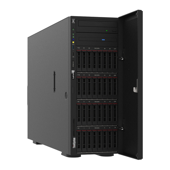
Page 26: Front View
The front view of the server varies by model. The illustrations in this topic show the server front views based on the supported drive bays. Note: Your server might look different from the illustrations in this topic. ThinkSystem ST650 V2 Maintenance Manual... - Page 27 Server models with twelve 3.5-inch simple-swap drive bays Figure 4. Front view of server models with twelve 3.5-inch simple-swap drive bays Table 3. Components on server models with twelve 3.5-inch simple-swap drive bays Front panel 3.5-inch simple-swap drive bays 4-7 Optical-drive bays 1-2 3.5-inch simple-swap drive bays 0-3 3.5-inch simple-swap drive bays 8-11...
- Page 28 The upper 5.25-inch optical-drive bay is for a secondary optical drive or a tape drive. Some models have a secondary optical drive or a tape drive installed. 5 6 7 3.5-inch hot-swap drive bays ThinkSystem ST650 V2 Maintenance Manual...
- Page 29 The drive bays are used to install 3.5-inch hot-swap drives. When you install drives, follow the order of the drive bay numbers. The EMI integrity and cooling of the server are protected by having all drive bays occupied. The vacant drive bays must be occupied by drive bay fillers or drive fillers. Note: For 3.5-inch drive bay models that support NVMe drives, you can install up to eight NVMe drives in bays 0-3 and 4-7.
- Page 30 Optical-drive bays 1-2 Foot stands 2.5-inch hot-swap drive bays 24-31 Front panel For information about the controls, connectors, and status LEDs on the front panel, see “Front panel” on page 21. Drive activity LED (green) ThinkSystem ST650 V2 Maintenance Manual...
-
Page 31: Front Panel
Each hot-swap drive comes with an activity LED. When this LED is flashing, it indicates that the drive is in use. Drive status LED (yellow) These LEDs are on SAS or SATA hard disk drives and solid-state drives, and indicate the following status: Lit: The drive has failed. - Page 32 System error LED (yellow) Simple-swap drive activity LED (green) USB 3.2 Gen 1 connector Network activity LED (green) USB 2.0 connector with Lenovo XClarity Controller management System ID button with system ID LED (blue) Power button with power status LED (green) Press this button to turn the server on and off manually.
- Page 33 Each time you press the system ID button, the state of both the system ID LEDs changes. The LEDs can be changed to on, blinking, or off. You can also use the Lenovo XClarity Controller or a remote management program to change the state of the system ID LEDs to assist in visually locating the server among other servers.
-
Page 34: Rear View
Install power supply units to these bays, connect them to power cords. Make sure the power cords are connected properly. You can purchase a power supply option from Lenovo and install the power supply to provide power redundancy without turning off the server. - Page 35 You can also use it to force a blue-screen memory dump. Use this button only when you are directed to do so by Lenovo Support. PCIe slots 1-4 (top to bottom) Install PCIe adapters into these slots.
-
Page 36: Rear View Leds
During normal operation, both the ac and dc power LEDs are lit. 10Gb ethernet link LED (green) 10Gb ethernet activity LED (green) Each 10Gb ethernet connector has two status LEDs. ThinkSystem ST650 V2 Maintenance Manual... -
Page 37: External Lcd Diagnostics Handset
Each time you press the system ID button on the front panel, the state of both the system ID LEDs changes. The LEDs can be changed to on, blinking, or off. You can also use the Lenovo XClarity Controller or a remote management program to change the state of the system ID LEDs to assist in visually locating the server among other servers. - Page 38 Note: When unplugging the external handset, see the following instructions: Press the plastic clip on the plug forward. Hold the clip and remove the cable from the connector. Display panel overview The diagnostics device consists of an LCD display and 5 navigation buttons. ThinkSystem ST650 V2 Maintenance Manual...
- Page 39 LCD display Scroll buttons (up/down/left/right) Press the scroll buttons to locate and select system information. Select button Press the select button to select from the options in the menu. Option flow diagram The external LCD diagnostics handset displays various system information. Navigate through the options with the scroll keys.
- Page 40 Following is the list of available options. Switch between an option and the subordinate information entries with the select button, and switch among options or information entries with the scroll buttons. Depending on the model, the options and entries on the LCD display might be different. ThinkSystem ST650 V2 Maintenance Manual...
- Page 41 Home Menu (System Status Dashboard) Home Menu Example System name System status Active alert quantity Temperature Power consumption Checkpoint code Active Alerts Sub Menu Example Home screen: Active error quantity Note: The “Active Alerts” menu displays only the quantity 1 Active Alerts of active errors.
- Page 42 • Static IPv6 IP IPv4 Network Mask • Current IPv6 Gateway :x.x.x.x IPv4 Default Gateway • IPv6 DNS : x.x.x.x Note: Only the MAC address that is currently in use is displayed (extension or shared). ThinkSystem ST650 V2 Maintenance Manual...
-
Page 43: System Board Components
System Environmental Information Sub Menu Example Ambient Temp: 24 C Exhaust Temp: 30 C • Ambient temperature PSU1: Vin= 213 w Inlet= 26 C • Exhaust temperature • PSU status FAN1 Front: 21000 RPM • Spinning speed of fans by RPM FAN2 Front: 21000 RPM FAN3 Front:... - Page 44 DIMM 1-8 slots (processor 1) PCIe 4 connector Intrusion switch connector M.2 signal connector PCIe slot 4 (processor 2) Fan 1 connector PCIe slot 3 (processor 1) Front USB connector PCIe slot 2 (processor 1) ThinkSystem ST650 V2 Maintenance Manual...
-
Page 45: System Board Leds
Table 10. Components on the system board (continued) M.2 power connector PCIe slot 1 (processor 1) SATA 4-7 connector Notes: • Trusted Platform Module • Trusted Cryptography Module • PCIe slot 8 is disabled by default. Connect PCIe slot 8 enable connector to NVMe 4 connector to enable PCIe slot 8. -
Page 46: System Board Switches
• Any system board switch that is not shown in the illustrations in this document are reserved. Note: If there is a clear protective sticker on the top of the switch blocks, you must remove and discard it to access the switches. ThinkSystem ST650 V2 Maintenance Manual... - Page 47 Figure 13. System board switches Table 12. System board switches SW3 switch block SW2 switch block Table 13. SW2 switch block definition Default Switch Description Definition position number Trusted Platform Changing this switch to the On position indicates a physical Module (TPM) physical presence to the TPM.
-
Page 48: Server Locks
You can remove the key attached on the rear of the server and use it to unlock or lock the server cover and the front door of the server. ThinkSystem ST650 V2 Maintenance Manual... -
Page 49: Backplates And Backplanes
Figure 14. Server cover and front door lock Backplates and backplanes Use the section to understand the internal connectors on the backplate or the backplane you use. 2.5-inch drive backplanes Use this information to locate the connectors on the 2.5-inch drive backplanes. 2.5-inch SAS/SATA 8-bay backplane SAS/SATA connector Power connector... -
Page 50: 3.5-Inch Drive Backplanes
Figure 16. 2.5-inch SAS/SATA/NVMe and NVMe 8-bay backplane connectors 3.5-inch drive backplanes Use this information to locate the connectors on the 3.5-inch drive backplanes. 3.5-inch SAS/SATA 4-bay backplane Power connector SAS/SATA connector Figure 17. 3.5-inch SAS/SATA 4-bay backplane connectors ThinkSystem ST650 V2 Maintenance Manual... -
Page 51: 3.5-Inch Drive Backplate
3.5-inch SAS/SATA/NVMe and NVMe 4-bay backplane NVMe 0-1 connector Power connector NVMe 2-3 connector SAS/SATA connector Figure 18. 3.5-inch SAS/SATA/NVMe and NVMe 4-bay backplane connectors 3.5-inch drive backplate Use this information to locate the connectors on the 3.5-inch drive backplate. 3.5-inch SAS/SATA 4-bay backplate Signal cable Power cable... -
Page 52: Parts List
BP 4 power connector Parts list Use the parts list to identify each of the components that are available for your server. Note: Depending on the model, your server might look slightly different from the illustration. ThinkSystem ST650 V2 Maintenance Manual... - Page 53 Tier 1 CRU at your request with no service agreement, you will be charged for the installation. • Tier 2 customer replaceable unit (CRU): You may install a Tier 2 CRU yourself or request Lenovo to install it, at no additional charge, under the type of warranty service that is designated for your server.
- Page 54 √ bay) Filler, 2.5-inch storage drive (eight bay) √ Bracket kit (drive retainer and PCIe √ bracket) 3.5-inch simple-swap drive backplate √ 3.5-inch hot-swap drive backplane √ 2.5-inch hot-swap drive backplane √ Front bezel √ ThinkSystem ST650 V2 Maintenance Manual...
- Page 55 Table 16. Parts listing (continued) Consumable Description Index Tier 1 CRU Tier 2 CRU Structural parts Foot stand √ Chassis √ System board √ M.2 boot adapter √ M.2 retainer clip √ M.2 drive √ Internal CFF RAID adapter √ TPM card (for Chinese Mainland only) √...
-
Page 56: Power Cords
The cord set should have the appropriate safety approvals for the country in which the equipment will be installed. • Power cords for a specific country or region are usually available only in that country or region. ThinkSystem ST650 V2 Maintenance Manual... -
Page 57: Chapter 3. Internal Cable Routing
• Ensure that the cable is not pinched and does not cover any connectors or obstruct any components on the system board. • Ensure that the relevant cables pass through the cable clips and guides. Figure 22. Cable clips and guides on 2.5-inch chassis © Copyright Lenovo 2021... -
Page 58: Backplane And Backplate Cable Routing
Any damage to the cable sockets might require replacing the system board. Backplane and backplate cable routing For more information about the backplane and backplate cable routing, see ThinkSystem ST650 V2 Backplane/Backplate Cable Routing Guide. -
Page 59: Front Usb Cable Routing
Figure 24. Cable routing for front panel Front USB cable routing Use the section to understand the cable routing for the front USB. From Rear of front panel System board: Front USB connector Notes: ↔ ↔ ↔ ↔ • Connections between connectors; , ... -
Page 60: Gpu Cable Routing
System board: CFF RAID power connector Notes: ↔ ↔ ↔ ↔ • Connections between connectors; , ... • When routing the cables, ensure that all cables are routed appropriately through the cable guides and cable clips. ThinkSystem ST650 V2 Maintenance Manual... -
Page 61: M.2 Boot Adapter Cable Routing
Figure 27. Cable routing for the CFF RAID adapter M.2 boot adapter cable routing Use the section to understand the cable routing for the M.2 boot adapter. From M.2 power connector on the M.2 boot adapter System board: M.2 power connector M.2 signal connector on the M.2 boot adapter System board: M.2 signal connector Notes:... -
Page 62: Optical Drive Cable Routing
System board: PCIe 4 connector Notes: ↔ ↔ ↔ ↔ • Connections between connectors; , ... • When routing the cables, ensure that all cables are routed appropriately through the cable guides and cable clips. ThinkSystem ST650 V2 Maintenance Manual... -
Page 63: Power Distribution Board Cable Routing
Figure 30. Cable routing to enable PCIe slot 8 Power distribution board cable routing Use the section to understand the cable routing for the power distribution board. From Power distribution board: Main power connector System board: Power distribution board power connector Power distribution board: PDB signal connector System board: Power distribution board signal connector Notes:... -
Page 64: Tape Drive Cable Routing
• The following illustrations show the cable routing for PCIe slot 1 and 9 respectively, the routing for the other PCIe slots are similar. Figure 32. Cable routing for SAS tape drive to PCIe slot 1 ThinkSystem ST650 V2 Maintenance Manual... - Page 65 Figure 33. Cable routing for SAS tape drive to PCIe slot 9 USB tape drive From Power connector on tape drive Power distribution board: ODD power connector Signal connector on tape drive System board: Internal USB connector 4 Notes: ↔ ↔...
- Page 66 ThinkSystem ST650 V2 Maintenance Manual...
-
Page 67: Chapter 4. Hardware Replacement Procedures
Go to to download firmware updates for your server. ThinkSystem ST650 V2 Drivers and Software Important: Some cluster solutions require specific code levels or coordinated code updates. If the component is part of a cluster solution, verify that the latest level of code is supported for the cluster solution before you update the code. -
Page 68: Safety Inspection Checklist
1 & IEC 60950-1, the standard for Safety of Electronic Equipment within the Field of Audio/Video, Information Technology and Communication Technology. Lenovo assumes you are qualified in the servicing of equipment and trained in recognizing hazards energy levels in products. -
Page 69: System Reliability Guidelines
Click the Power tab to see all line cords. • Make sure that the insulation is not frayed or worn. 3. Check for any obvious non-Lenovo alterations. Use good judgment as to the safety of any non-Lenovo alterations. 4. Check inside the server for any obvious unsafe conditions, such as metal filings, contamination, water or other liquid, or signs of fire or smoke damage. -
Page 70: Handling Static-Sensitive Devices
Note: This topic applies only to server models that have 2.5-inch hot-swap drive backplanes installed. Remove a 2.5-inch hot-swap drive backplane Use this information to remove a 2.5-inch hot-swap drive backplane. About this task S002 CAUTION: ThinkSystem ST650 V2 Maintenance Manual... - Page 71 The power-control button on the device and the power switch on the power supply do not turn off the electrical current supplied to the device. The device also might have more than one power cord. To remove all electrical current from the device, ensure that all power cords are disconnected from the power source.
-
Page 72: Install A 2.5-Inch Hot-Swap Drive Backplane
Watch the procedure. A video of the installation and removal process is available: • YouTube: https://youtube.com/playlist?list=PLYV5R7hVcs-DoEcxrm2zKNpaKOdZ3f8Qc • Youku: https://list.youku.com/albumlist/show/id_59636516 Procedure Step 1. Install the backplane. ThinkSystem ST650 V2 Maintenance Manual... -
Page 73: Inch Drive Replacement From 3.5-Inch Drive
• Reconnect the cables to the backplane. See “2.5-inch hot-swap drive backplane cable routing” in the ThinkSystem ST650 V2 Backplane/Backplate Cable Routing Guide. • Reinstall all the hot-swap drives and drive bay fillers (if any) into the drive bays. See “Install a hot-swap drive”... -
Page 74: Remove A 2.5-Inch Drive From A 3.5-Inch Drive
Remove the five screws that secure the 2.5-inch drive and the drive adapter; then, remove the 2.5- inch drive and the drive adapter from the tray. Figure 37. Removing the screws that secure the 2.5-inch drive and the drive adapter ThinkSystem ST650 V2 Maintenance Manual... -
Page 75: Install A 2.5-Inch Drive Into A 3.5-Inch Drive
Step 5. Remove the two screws that secure the 2.5-inch drive; then, lift the drive up to remove it from the drive adapter. Figure 38. 2.5-inch drive removal from the drive adapter After you finish If you are instructed to return the component or optional device, follow all packaging instructions, and use any packaging materials for shipping that are supplied to you. -
Page 76: 3.5-Inch Hot-Swap Drive Backplane Replacement
3. Complete the parts replacement. See “Complete the parts replacement” on page 206. 3.5-inch hot-swap drive backplane replacement Use this information to remove and install a 3.5-inch hot-swap drive backplane. Note: This topic applies only to server models that have 3.5-inch hot-swap drive backplanes installed. ThinkSystem ST650 V2 Maintenance Manual... -
Page 77: Remove A 3.5-Inch Hot-Swap Drive
Remove a 3.5-inch hot-swap drive backplane Use this information to remove a 3.5-inch hot-swap drive backplane. About this task S002 CAUTION: The power-control button on the device and the power switch on the power supply do not turn off the electrical current supplied to the device. -
Page 78: Install A 3.5-Inch Hot-Swap Drive Backplane
• Prevent exposure to static electricity, which might lead to system halt and loss of data, by keeping static- sensitive components in their static-protective packages until installation, and handling these devices with an electrostatic-discharge wrist strap or other grounding system. ThinkSystem ST650 V2 Maintenance Manual... -
Page 79: 3.5-Inch Simple-Swap Drive Backplate Replacement
1. Reconnect the cables to the backplane. See “3.5-inch hot-swap drive backplane cable routing” in the ThinkSystem ST650 V2 Backplane/Backplate Cable Routing Guide. 2. Reinstall all the hot-swap drives and drive bay fillers (if any) into the drive bays. See “Install a hot-swap drive”... - Page 80 Remove all installed simple-swap drives and drive bay fillers (if any) from the drive bays. See “Remove a simple-swap drive” on page 80. Step 2. Disconnect all cables connected to the system board. Step 3. Remove the backplate. ThinkSystem ST650 V2 Maintenance Manual...
-
Page 81: Install A 3.5-Inch Simple-Swap Drive
Figure 43. Removal of the 3.5-inch hot-swap drive backplate Open the plunger that secures the backplate. Slightly slide the backplate as shown to disengage it from the drive cage; then, remove the backplate from the drive cage. After you finish If you are instructed to return the component or optional device, follow all packaging instructions, and use any packaging materials for shipping that are supplied to you. -
Page 82: Air Baffle Replacement
Figure 44. Installation of the 3.5-inch hot-swap drive backplate Step 3. Connect the power cable and the signal cable to the system board. See “3.5-inch simple-swap drive backplate cable routing” in the ThinkSystem ST650 V2 Backplane/Backplate Cable Routing Guide. After you finish 1. - Page 83 About this task S033 CAUTION: Hazardous energy present. Voltages with hazardous energy might cause heating when shorted with metal, which might result in spattered metal, burns, or both. S017 CAUTION: Hazardous moving fan blades nearby. Keep fingers and other body parts away. Attention: •...
-
Page 84: Install The Air Baffle
Follow this procedure to install the air baffle. About this task S033 CAUTION: Hazardous energy present. Voltages with hazardous energy might cause heating when shorted with metal, which might result in spattered metal, burns, or both. S017 ThinkSystem ST650 V2 Maintenance Manual... - Page 85 CAUTION: Hazardous moving fan blades nearby. Keep fingers and other body parts away. Attention: • Read “Installation guidelines” on page 57 to ensure that you work safely. • Power off the server and disconnect all power cords for this task. •...
-
Page 86: Cmos Battery (Cr2032) Replacement
S004 CAUTION: When replacing the lithium battery, use only Lenovo specified part number or an equivalent type battery recommended by the manufacturer. If your system has a module containing a lithium battery, replace it only with the same module type made by the same manufacturer. The battery contains lithium and can explode if not properly used, handled, or disposed of. - Page 87 CAUTION: The battery is a lithium ion battery. To avoid possible explosion, do not burn the battery. Exchange it only with the approved part. Recycle or discard the battery as instructed by local regulations. Attention: • Read “Installation guidelines” on page 57 to ensure that you work safely. •...
-
Page 88: Install The Cmos Battery (Cr2032)
S004 CAUTION: When replacing the lithium battery, use only Lenovo specified part number or an equivalent type battery recommended by the manufacturer. If your system has a module containing a lithium battery, replace it only with the same module type made by the same manufacturer. The battery contains lithium and can explode if not properly used, handled, or disposed of. -
Page 89: Drive Replacement
• After replacing the CMOS battery, make sure to reconfigure the server and reset system date and time. • Lenovo has designed this product with your safety in mind. The lithium battery must be handled correctly to avoid possible danger. If you install the CMOS battery, you must adhere to the following instructions. -
Page 90: Remove A Simple-Swap Drive
• Before you remove any component of a RAID array, back up all RAID configuration information. Watch the procedure. A video of the installation and removal process is available: • YouTube: https://youtube.com/playlist?list=PLYV5R7hVcs-DoEcxrm2zKNpaKOdZ3f8Qc • Youku: https://list.youku.com/albumlist/show/id_59636516 Procedure ThinkSystem ST650 V2 Maintenance Manual... -
Page 91: Install A Simple-Swap Drive
Step 1. Use the key to unlock the server cover; then, open the front door. Step 2. Locate the simple-swap drive you want to remove. Step 3. Remove the simple-swap drive. Figure 49. Opening the tray handle of a 3.5-inch simple-swap drive Use a screwdriver to turn the handle lock to the unlocked position. - Page 92 Close the tray handle to lock the drive in place. After you finish 1. Install other drives or drive fillers if necessary. ThinkSystem ST650 V2 Maintenance Manual...
-
Page 93: Remove A Hot-Swap Drive
Solid on Green None The simple-swap drive is not active. 4. Use the Lenovo XClarity Provisioning Manager to configure the RAID if necessary. For more information, see: http://sysmgt.lenovofiles.com/help/index.jsp?topic=%2FLXPM%2FRAID_setup.html 5. Complete the parts replacement. See “Complete the parts replacement” on page 206. -
Page 94: Install A Hot-Swap Drive
Use this information to install a hot-swap drive. About this task S033 CAUTION: Hazardous energy present. Voltages with hazardous energy might cause heating when shorted with metal, which might result in spattered metal, burns, or both. ThinkSystem ST650 V2 Maintenance Manual... - Page 95 The following notes describe the type of drives that your server supports and other information that you must consider when you install a drive. • For a complete list of supported optional devices for the server, see: https://static.lenovo.com/us/en/ serverproven/index.shtml • The drive bays are numbered to indicate the installation order (starting from number “0”). Follow the installation order when you install a drive.
-
Page 96: Eia Brackets Replacement
Blinking yellow (blinking rapidly, about The RAID adapter is locating the drive. four flashes per second) 4. Use the Lenovo XClarity Provisioning Manager to configure the RAID if necessary. For more information, see: http://sysmgt.lenovofiles.com/help/index.jsp?topic=%2FLXPM%2FRAID_setup.html 5. Complete the parts replacement. See “Complete the parts replacement” on page 206. - Page 97 • YouTube: https://youtube.com/playlist?list=PLYV5R7hVcs-DoEcxrm2zKNpaKOdZ3f8Qc • Youku: https://list.youku.com/albumlist/show/id_59636516 Procedure Step 1. Lay the server on its side. Step 2. Use a screwdriver to remove the three screws that secure the right EIA bracket; then, remove the right EIA bracket. Figure 53. Right EIA bracket removal Step 3.
-
Page 98: Install The Eia Brackets
• Prevent exposure to static electricity, which might lead to system halt and loss of data, by keeping static- sensitive components in their static-protective packages until installation, and handling these devices with an electrostatic-discharge wrist strap or other grounding system. ThinkSystem ST650 V2 Maintenance Manual... - Page 99 Watch the procedure. A video of the installation and removal process is available: • YouTube: https://youtube.com/playlist?list=PLYV5R7hVcs-DoEcxrm2zKNpaKOdZ3f8Qc • Youku: https://list.youku.com/albumlist/show/id_59636516 Procedure Step 1. Align the holes in the right EIA bracket with the corresponding holes on the top of the chassis; then, use a screwdriver to install the three screws to secure the right EIA bracket Figure 55.
-
Page 100: Expansion Drive Cage Replacement
The device also might have more than one power cord. To remove all electrical current from the device, ensure that all power cords are disconnected from the power source. Attention: • Read “Installation guidelines” on page 57 to ensure that you work safely. ThinkSystem ST650 V2 Maintenance Manual... -
Page 101: Install The Expansion Drive Cage
• Power off the server and disconnect all power cords for this task. • Prevent exposure to static electricity, which might lead to system halt and loss of data, by keeping static- sensitive components in their static-protective packages until installation, and handling these devices with an electrostatic-discharge wrist strap or other grounding system. - Page 102 Carefully push the expansion drive cage at the same time to slide it into the bay until it snaps into position. After you finish 1. Reconnect the cables to the backplane. See “3.5-inch hot-swap drive backplane cable routing” in the ThinkSystem ST650 V2 Backplane/Backplate Cable Routing Guide. ThinkSystem ST650 V2 Maintenance Manual...
-
Page 103: Fan And Fan Cage Replacement
2. Reinstall all the hot-swap drives and drive bay fillers (if any) into the drive bays. See “Install a hot-swap drive” on page 84. 3. Reinstall the front bezel. See “Install the front bezel” on page 106. 4. Reinstall the front door. See “Install the front door” on page 109. 5. -
Page 104: Install A Hot-Swap Fan
Install a hot-swap fan Use this procedure to install a hot-swap fan. About this task S017 CAUTION: Hazardous moving fan blades nearby. Keep fingers and other body parts away. S033 CAUTION: ThinkSystem ST650 V2 Maintenance Manual... -
Page 105: Remove The Fan Cage Assembly
Locate the required fan slot in the fan cage. Note: Ensure that you observe the installation rules and sequence in “Technical rules for system fans” in the ThinkSystem ST650 V2 Setup Guide. Step 2. Align the fan over the fan slot in the fan cage assembly. - Page 106 Remove the air baffle. See “Remove the air baffle” on page 72. Remove all the full-length GPU adapters. See “Remove a full-length GPU adapter” on page 113. Remove all the fans. See “Remove a hot-swap fan” on page 93. Step 2. Remove the fan cage assembly. ThinkSystem ST650 V2 Maintenance Manual...
-
Page 107: Install The Fan Cage Assembly
Figure 61. Fan cage assembly removal Lift and rotate the fan cage release latches to disengage the fan cage assembly from the server. Lift the fan cage assembly from the server. After you finish If you are instructed to return the component or optional device, follow all packaging instructions, and use any packaging materials for shipping that are supplied to you. -
Page 108: Flash Power Module Replacement
The flash power module protects the cache memory on the installed RAID adapter. You can purchase a flash power module from Lenovo. For a list of supported options, see: https://static.lenovo.com/us/en/serverproven/index.shtml Remove a flash power module Use this information to remove a flash power module. ThinkSystem ST650 V2 Maintenance Manual... - Page 109 About this task S002 CAUTION: The power-control button on the device and the power switch on the power supply do not turn off the electrical current supplied to the device. The device also might have more than one power cord. To remove all electrical current from the device, ensure that all power cords are disconnected from the power source.
-
Page 110: Install A Flash Power Module
Attention: • Read “Installation guidelines” on page 57 to ensure that you work safely. • Power off the server and disconnect all power cords for this task. ThinkSystem ST650 V2 Maintenance Manual... - Page 111 • Prevent exposure to static electricity, which might lead to system halt and loss of data, by keeping static- sensitive components in their static-protective packages until installation, and handling these devices with an electrostatic-discharge wrist strap or other grounding system. Locate the flash power module slot on the air baffle.
-
Page 112: Foot Stands Replacement
Hazardous energy present. Voltages with hazardous energy might cause heating when shorted with metal, which might result in spattered metal, burns, or both. Attention: • Read “Installation guidelines” on page 57 to ensure that you work safely. ThinkSystem ST650 V2 Maintenance Manual... - Page 113 • Prevent exposure to static electricity, which might lead to system halt and loss of data, by keeping static- sensitive components in their static-protective packages until installation, and handling these devices with an electrostatic-discharge wrist strap or other grounding system. Watch the procedure.
-
Page 114: Install The Foot Stands
For each foot stand, carefully align the pin and screw hole on the foot stand with the corresponding hole on the chassis; then, use a screwdriver to install a screw to secure the foot stand. Figure 70. Foot stand installation Step 2. For each foot stand, rotate the foot stand outwards. ThinkSystem ST650 V2 Maintenance Manual... -
Page 115: Front Bezel Replacement
Figure 71. Foot stand adjustment Important: To help the server stand steadily, ensure that the foot stands are rotated outward. After you finish Complete the parts replacement. See “Complete the parts replacement” on page 206. Front bezel replacement Use this information to remove and install the front bezel. Remove the front bezel Use this information to remove the front bezel. -
Page 116: Install The Front Bezel
Use this information to install the front bezel. About this task S033 CAUTION: Hazardous energy present. Voltages with hazardous energy might cause heating when shorted with metal, which might result in spattered metal, burns, or both. Attention: ThinkSystem ST650 V2 Maintenance Manual... -
Page 117: Front Door Replacement
• Read “Installation guidelines” on page 57 to ensure that you work safely. • Prevent exposure to static electricity, which might lead to system halt and loss of data, by keeping static- sensitive components in their static-protective packages until installation, and handling these devices with an electrostatic-discharge wrist strap or other grounding system. - Page 118 Lift the front door slightly upwards until you can completely remove it. After you finish If you are instructed to return the component or optional device, follow all packaging instructions, and use any packaging materials for shipping that are supplied to you. ThinkSystem ST650 V2 Maintenance Manual...
-
Page 119: Install The Front Door
Install the front door Use this information to install the front door. About this task S033 CAUTION: Hazardous energy present. Voltages with hazardous energy might cause heating when shorted with metal, which might result in spattered metal, burns, or both. Attention: •... -
Page 120: Front Panel Board Assembly Replacement
Remove all the flash power modules. See “Remove a flash power module” on page 98. Remove the air baffle. See “Remove the air baffle” on page 72. Remove all the full-length GPU adapters. See “Remove a full-length GPU adapter” on page 113. ThinkSystem ST650 V2 Maintenance Manual... -
Page 121: Install The Front Panel Board Assembly
Remove all the fans. See “Remove a hot-swap fan” on page 93. Remove the fan cage. See “Remove the fan cage assembly” on page 95. Remove the front door. See “Remove the front door” on page 107. Remove the front bezel. See “Remove the front bezel” on page 105. Step 2. - Page 122 7. Reinstall all the flash power modules. See “Install a flash power module” on page 100. 8. Reinstall the server cover. See “Install the server cover” on page 190. 9. Complete the parts replacement. See “Complete the parts replacement” on page 206. ThinkSystem ST650 V2 Maintenance Manual...
-
Page 123: Full-Length Gpu Adapter Replacement
GPU adapter if necessary. Notes: • For a list of the supported GPU adapters, see: https://static.lenovo.com/us/en/serverproven/index.shtml • For instructions on how to remove and install a half-length GPU adapter or PCIe adapter, see “PCIe adapter replacement” on page 162 Remove a full-length GPU adapter Use this information to remove a full-length GPU adapter. -
Page 124: Install A Full-Length Gpu Adapter
3. If you are instructed to return the component or optional device, follow all packaging instructions, and use any packaging materials for shipping that are supplied to you. Install a full-length GPU adapter Use this information to install a full-length GPU adapter. About this task ThinkSystem ST650 V2 Maintenance Manual... - Page 125 PCIe slots in your server. Note: Ensure that you observe the installation rules and sequence in “Technical rules for PCIe adapters” in the ThinkSystem ST650 V2 Setup Guide. Step 2. Make sure you have installed a PCIe adapter holder corresponding to the PCIe slot for your full- length GPU adapter.
-
Page 126: Gpu Filler Replacement
Use this information to remove a GPU filler. About this task S033 CAUTION: Hazardous energy present. Voltages with hazardous energy might cause heating when shorted with metal, which might result in spattered metal, burns, or both. ThinkSystem ST650 V2 Maintenance Manual... - Page 127 S017 CAUTION: Hazardous moving fan blades nearby. Keep fingers and other body parts away. Attention: • Read “Installation guidelines” on page 57 to ensure that you work safely. • Prevent exposure to static electricity, which might lead to system halt and loss of data, by keeping static- sensitive components in their static-protective packages until installation, and handling these devices with an electrostatic-discharge wrist strap or other grounding system.
-
Page 128: Install A Gpu Filler
• YouTube: https://youtube.com/playlist?list=PLYV5R7hVcs-DoEcxrm2zKNpaKOdZ3f8Qc • Youku: https://list.youku.com/albumlist/show/id_59636516 Procedure Step 1. Align the GPU filler with the corresponding slots on the air baffle. Step 2. Insert the GPU filler onto the air baffle until it snaps into position ThinkSystem ST650 V2 Maintenance Manual... -
Page 129: Heat Sink Torx T30 Nut Replacement
Figure 81. GPU filler installation After you finish 1. Reinstall the server cover. See “Install the server cover” on page 190. 2. Complete the parts replacement. See “Complete the parts replacement” on page 206. Heat sink Torx T30 nut replacement Use this information to remove and install a heat sink Torx T30 nut. - Page 130 1. Install a new Torx T30 nut. See “Install a heat sink Torx T30 nut” on page 121. 2. If you are instructed to return the component or optional device, follow all packaging instructions, and use any packaging materials for shipping that are supplied to you. ThinkSystem ST650 V2 Maintenance Manual...
-
Page 131: Install A Heat Sink Torx T30 Nut
Install a heat sink Torx T30 nut This task has instructions for installing a PEEK (Polyether ether ketone) Torx T30 nut on the heat sink. About this task S002 CAUTION: The power-control button on the device and the power switch on the power supply do not turn off the electrical current supplied to the device. -
Page 132: Internal Cff Adapter Replacement
Use this information to remove and install the internal CFF RAID adapter, internal CFF HBA adapter, or internal CFF RAID expander adapter. Remove the internal CFF adapter Use this information to remove the internal CFF RAID adapter, internal CFF HBA adapter, or internal CFF RAID expander adapter. About this task S002 ThinkSystem ST650 V2 Maintenance Manual... - Page 133 CAUTION: The power-control button on the device and the power switch on the power supply do not turn off the electrical current supplied to the device. The device also might have more than one power cord. To remove all electrical current from the device, ensure that all power cords are disconnected from the power source.
-
Page 134: Install The Internal Cff Adapter
Install the internal CFF adapter Use this information to install the internal CFF RAID adapter, internal CFF HBA adapter, or internal CFF RAID expander adapter. ThinkSystem ST650 V2 Maintenance Manual... - Page 135 About this task S002 CAUTION: The power-control button on the device and the power switch on the power supply do not turn off the electrical current supplied to the device. The device also might have more than one power cord. To remove all electrical current from the device, ensure that all power cords are disconnected from the power source.
- Page 136 Connect the cables to the CFF adapter. See “Internal CFF RAID adapter cable routing” on page 50. After you finish 1. Connect the cables to the backplane. See ThinkSystem ST650 V2 Backplane/Backplate Cable Routing Guide. 2. Reinstall the fan cage. See “Install the fan cage assembly” on page 97.
-
Page 137: Intrusion Switch Replacement
7. Reinstall the server cover. See “Install the server cover” on page 190. 8. Complete the parts replacement. See “Complete the parts replacement” on page 206. Intrusion switch replacement Use this information to remove and install the intrusion switch. The intrusion switch informs you that the server cover is not properly installed or closed by creating an event in the system event log (SEL). -
Page 138: Install The Intrusion Switch
The device also might have more than one power cord. To remove all electrical current from the device, ensure that all power cords are disconnected from the power source. Attention: • Read “Installation guidelines” on page 57 to ensure that you work safely. ThinkSystem ST650 V2 Maintenance Manual... - Page 139 • Power off the server and disconnect all power cords for this task. • Prevent exposure to static electricity, which might lead to system halt and loss of data, by keeping static- sensitive components in their static-protective packages until installation, and handling these devices with an electrostatic-discharge wrist strap or other grounding system.
-
Page 140: M.2 Boot Adapter Replacement
Remove the fan cage. See “Remove the fan cage assembly” on page 95. Remove all the M.2 drives from the M.2 boot adapter. See “Remove an M.2 drive” on page 133 Step 2. Disconnect the cables from the M.2 boot adapter. ThinkSystem ST650 V2 Maintenance Manual... -
Page 141: Install The M.2 Boot Adapter
Figure 92. M.2 signal cable screw removal Loosen the screw that secures the M.2 signal cable to the M.2 boot adapter. Disconnect all the cables. Step 3. Remove the M.2 boot adapter. Figure 93. M.2 boot adapter removal Loosen the screw that secures the M.2 boot adapter to the chassis. Slightly slide the M.2 boot adapter as shown and carefully lift it out of the chassis. - Page 142 Tighten the screw that secures the M.2 signal cable to the M.2 boot adapter. Step 3. Connect the power cable and the signal cable to the system board. See “M.2 boot adapter cable routing” on page 51. ThinkSystem ST650 V2 Maintenance Manual...
-
Page 143: M.2 Drive Replacement
After you finish 1. Reinstall the M.2 drives to the M.2 boot adapter. See “Install an M.2 drive” on page 135. 2. Reinstall the fan cage. See “Install the fan cage assembly” on page 97. 3. Reinstall all the fans. See “Install a hot-swap fan” on page 94. 4. -
Page 144: Adjust The Retainer On The M.2 Boot
• Prevent exposure to static electricity, which might lead to system halt and loss of data, by keeping static- sensitive components in their static-protective packages until installation, and handling these devices with an electrostatic-discharge wrist strap or other grounding system. ThinkSystem ST650 V2 Maintenance Manual... -
Page 145: Install An M.2 Drive
Before adjusting the retainer on the M.2 boot adapter, locate the correct keyhole that the retainer should be installed into to accommodate the particular size of the M.2 drive you wish to install. Note: The M.2 boot adapter might be different from the following illustrations, but the adjustment method is the same. - Page 146 Watch the procedure. A video of the installation and removal process is available: • YouTube: https://youtube.com/playlist?list=PLYV5R7hVcs-DoEcxrm2zKNpaKOdZ3f8Qc • Youku: https://list.youku.com/albumlist/show/id_59636516 Procedure Step 1. Install the M.2 drive Figure 99. M.2 drive installation Insert the M.2 drive at an angle of approximately 30 degrees into the connector. ThinkSystem ST650 V2 Maintenance Manual...
-
Page 147: Memory Module Replacement
Pivot the M.2 drive down until the notch catches on the lip of the retainer. Slide the retainer forward (towards the connector) to secure the M.2 drive into place. After you finish 1. Reinstall the server cover. See “Install the server cover” on page 190. 2. - Page 148 • Install a memory module filler or a new memory module to cover the slot. See “Install a memory module” on page 139. • If you are instructed to return the component or optional device, follow all packaging instructions, and use any packaging materials for shipping that are supplied to you. ThinkSystem ST650 V2 Maintenance Manual...
-
Page 149: Install A Memory Module
Locate the required memory module slot on the system board. Note: Ensure that you observe the installation rules and sequence in “Technical rules for memory modules” in the ThinkSystem ST650 V2 Setup Guide. Step 3. Install the memory module into the slot. - Page 150 5. Reinstall all the flash power modules. See “Install a flash power module” on page 100. 6. Reinstall the server cover. See “Install the server cover” on page 190. 7. Complete the parts replacement. See “Complete the parts replacement” on page 206. ThinkSystem ST650 V2 Maintenance Manual...
-
Page 151: Nvlink Bridge Replacement
NVLink bridge replacement Use this information to remove and install an NVLink bridge. Remove an NVLink bridge Use this information to remove an NVLink bridge. About this task Important: Make sure you have a suction cup available for properly removing the NVLink bridge. S002 CAUTION: The power-control button on the device and the power switch on the power supply do not turn off the... -
Page 152: Install An Nvlink Bridge
If you are instructed to return the component or optional device, follow all packaging instructions, and use any packaging materials for shipping that are supplied to you. Install an NVLink bridge Use this information to install an NVLink bridge. About this task ThinkSystem ST650 V2 Maintenance Manual... - Page 153 S002 CAUTION: The power-control button on the device and the power switch on the power supply do not turn off the electrical current supplied to the device. The device also might have more than one power cord. To remove all electrical current from the device, ensure that all power cords are disconnected from the power source.
-
Page 154: Optical Drive Cage Replacement
Attention: • Read “Installation guidelines” on page 57 to ensure that you work safely. • Power off the server and disconnect all power cords for this task. ThinkSystem ST650 V2 Maintenance Manual... -
Page 155: Install The Optical Drive Cage
• Prevent exposure to static electricity, which might lead to system halt and loss of data, by keeping static- sensitive components in their static-protective packages until installation, and handling these devices with an electrostatic-discharge wrist strap or other grounding system. •... - Page 156 1. Reinstall all the optical drives, tape drives, and fillers (if any) into the optical drive cage. See “Install an optical drive or a tape drive” on page 150 and “Install the 5.25-inch drive bay adapter assembly” on page 156. 2. Reinstall the front bezel. See “Install the front bezel” on page 106. ThinkSystem ST650 V2 Maintenance Manual...
-
Page 157: Optical Drive Or Tape Drive Replacement
3. Reinstall the front door. See “Install the front door” on page 109. 4. Reinstall the server cover. See “Install the server cover” on page 190. 5. Complete the parts replacement. See “Complete the parts replacement” on page 206. Optical drive or tape drive replacement Use this information to remove and install the optical drive or tape drive. - Page 158 Remove the optical drive or tape drive. Figure 108. Optical drive removal Press and hold the release tab. Carefully pull the optical drive or tape drive at the same time to remove it from the chassis. After you finish ThinkSystem ST650 V2 Maintenance Manual...
- Page 159 1. Install a new optical drive, tape drive, or filler to cover the drive bay. See “Install an optical drive or a tape drive” on page 150. To install a filler, complete the following steps: a. Insert the filler to the vacant drive bay. Figure 109.
-
Page 160: Install An Optical Drive Or A Tape Drive
• Do not remove the covers. Removing the covers of the laser product could result in exposure to hazardous laser radiation. There are no serviceable parts inside the device. • Use of controls or adjustments or performance of procedures other than those specified herein might result in hazardous radiation exposure. ThinkSystem ST650 V2 Maintenance Manual... - Page 161 S007 CAUTION: This product contains a Class 1M laser. Do not view directly with optical instruments. Attention: • Read “Installation guidelines” on page 57 to ensure that you work safely. • Power off the server and disconnect all power cords for this task. •...
- Page 162 Figure 113. Drive bay filler installation Step 3. Remove the retainer from the chassis. Figure 114. Drive retainer removal Step 4. Install the retainer to only the left side of the optical drive or tape drive. ThinkSystem ST650 V2 Maintenance Manual...
-
Page 163: Remove The 5.25-Inch Drive Bay Adapter
Figure 115. Optical drive retainer installation Step 5. Hold the optical drive or tape drive in the correct orientation; then, slide it into the drive bay until it snaps into position. Figure 116. Optical drive installation Step 6. Connect the power cable and the signal cable to the rear of the optical drive or tape drive. See “Optical drive cable routing”... - Page 164 Remove the server cover. See “Remove the server cover” on page 188. Remove the front door. See “Remove the front door” on page 107. Remove the front bezel. See “Remove the front bezel” on page 105. ThinkSystem ST650 V2 Maintenance Manual...
- Page 165 Step 2. Disconnect every cable from the 5.25-inch drive bay adapter assembly. Step 3. Remove the 5.25-inch drive bay adapter assembly. Figure 117. 5.25-inch drive bay adapter assembly removal Press and hold the release tab. Carefully pull the 5.25-inch drive bay adapter assembly at the same time to remove it from the chassis.
-
Page 166: Install The 5.25-Inch Drive Bay Adapter
2. If you are instructed to return the component or optional device, follow all packaging instructions, and use any packaging materials for shipping that are supplied to you. Install the 5.25-inch drive bay adapter assembly Use this information to install the 5.25-inch drive bay adapter assembly. ThinkSystem ST650 V2 Maintenance Manual... - Page 167 About this task S002 CAUTION: The power-control button on the device and the power switch on the power supply do not turn off the electrical current supplied to the device. The device also might have more than one power cord. To remove all electrical current from the device, ensure that all power cords are disconnected from the power source.
- Page 168 Remove the cover of the drive bay filler as shown. Step 2. If necessary, remove the drive bay filler out of the chassis. Figure 122. Drive bay filler installation Step 3. Install the slim optical drive into the adapter. ThinkSystem ST650 V2 Maintenance Manual...
-
Page 169: Pcie Adapter Holder Replacement
Figure 123. Installing slim optical drive into the drive bay adapter Slide the slim optical drive into the adapter. Secure the slim optical drive with two screws. Step 4. Hold the 5.25-inch drive bay adapter assembly in the correct orientation; then, slide it into the drive bay until it snaps into position. -
Page 170: Remove A Pcie Adapter Holder
Remove all the full-length GPU adapters. See “Remove a full-length GPU adapter” on page 113. Step 2. Press and hold the tab to release the PCIe adapter holder from the fan cage; then, remove the PCIe adapter holder in the direction as shown. ThinkSystem ST650 V2 Maintenance Manual... -
Page 171: Install A Pcie Adapter Holder
Figure 125. PCIe adapter holder removal After you finish If you are instructed to return the component or optional device, follow all packaging instructions, and use any packaging materials for shipping that are supplied to you. Install a PCIe adapter holder Use this information to install a PCIe adapter holder. -
Page 172: Pcie Adapter Replacement
• For instructions on how to remove and install a full-length GPU adapter, see “Full-length GPU adapter replacement” on page 113 Remove a PCIe adapter Use this information to remove a PCIe adapter. About this task S002 ThinkSystem ST650 V2 Maintenance Manual... - Page 173 CAUTION: The power-control button on the device and the power switch on the power supply do not turn off the electrical current supplied to the device. The device also might have more than one power cord. To remove all electrical current from the device, ensure that all power cords are disconnected from the power source.
-
Page 174: Install A Pcie Adapter
• Prevent exposure to static electricity, which might lead to system halt and loss of data, by keeping static- sensitive components in their static-protective packages until installation, and handling these devices with an electrostatic-discharge wrist strap or other grounding system. Notes: ThinkSystem ST650 V2 Maintenance Manual... - Page 175 PCIe slots in your server. Note: Ensure that you observe the installation rules and sequence in “Technical rules for PCIe adapters” in the ThinkSystem ST650 V2 Setup Guide. Step 2. If a bracket is installed in the PCIe slot, remove it. Store the bracket for the PCIe slot in case that you later remove the PCIe adapter and need the bracket to cover the place.
-
Page 176: Power Distribution Board Replacement
Remove all the PCIe adapters. See “Remove a PCIe adapter” on page 162. Remove all the full-length GPU adapters. See “Remove a full-length GPU adapter” on page 113. Remove all the fans. See “Remove a hot-swap fan” on page 93. ThinkSystem ST650 V2 Maintenance Manual... - Page 177 Remove the fan cage. See “Remove the fan cage assembly” on page 95. Remove the system board. See “Remove the system board” on page 192. Step 2. Remove the power distribution board cover. Figure 129. Power distribution board cover removal Loosen the captive screw.
-
Page 178: Install The Power Distribution Board
The device also might have more than one power cord. To remove all electrical current from the device, ensure that all power cords are disconnected from the power source. Attention: ThinkSystem ST650 V2 Maintenance Manual... - Page 179 • Read “Installation guidelines” on page 57 to ensure that you work safely. • Power off the server and disconnect all power cords for this task. • Prevent exposure to static electricity, which might lead to system halt and loss of data, by keeping static- sensitive components in their static-protective packages until installation, and handling these devices with an electrostatic-discharge wrist strap or other grounding system.
-
Page 180: Power Supply Unit Replacement
11. Complete the parts replacement. See “Complete the parts replacement” on page 206. Power supply unit replacement Use this information to remove and install the redundant power supply unit. Remove a hot-swap power supply Use this information to remove a hot-swap power supply. ThinkSystem ST650 V2 Maintenance Manual... - Page 181 About this task S001 DANGER Electrical current from power, telephone, and communication cables is hazardous. To avoid a shock hazard: • Connect all power cords to a properly wired and grounded electrical outlet/source. • Connect any equipment that will be attached to this product to properly wired outlets/sources. •...
- Page 182 Attention: This type of power supply is hot-swap only when two power supplies are installed for redundancy. If only one power supply is installed, you must power off the server first before removing the power supply. 在直流输入状态下,若电源供应器插座不支持热插拔功能,请务必不要对设备电源线进行热插拔,此操作可能 导致设备损坏及数据丢失。因错误执行热插拔导致的设备故障或损坏,不属于保修范围。 ThinkSystem ST650 V2 Maintenance Manual...
-
Page 183: Install The Hot-Swap Power Supply
NEVER CONNECT AND DISCONNECT THE POWER SUPPLY CABLE AND EQUIPMENT WHILE YOUR EQUIPMENT IS POWERED ON WITH DC SUPPLY (hot-plugging). Otherwise you may damage the equipment and result in data loss, the damages and losses result from incorrect operation of the equipment will not be covered by the manufacturers’... - Page 184 The following tips describe the type of power supply that the server supports and other information that you must consider when you install a power supply: ThinkSystem ST650 V2 Maintenance Manual...
- Page 185 • Ensure that the devices that you are installing are supported. For a list of supported optional devices for the server, go to: https://static.lenovo.com/us/en/serverproven/index.shtml CAUTION: 1. 240 V dc input (input range: 180-300 V dc) is ONLY supported in Chinese Mainland.
- Page 186 2. If the server is powered off, power on the server. Ensure that both the power input LED and the power output LED on the power supply are lit, indicating that the power supply is operating properly. 3. Complete the parts replacement. See “Complete the parts replacement” on page 206. ThinkSystem ST650 V2 Maintenance Manual...
-
Page 187: Processor And Heat Sink Replacement
Processor and heat sink replacement Use this information to remove and install a processor and heat sink. Attention: Before you begin replacing a processor, make sure that you have an alcohol cleaning pad (part number 00MP352) and thermal grease. Remove a processor and heat sink This task has instructions for removing an assembled processor and heat sink, known as a processor-heat- sink module (PHM). - Page 188 Figure 137. Processor locations on system board Note: The heat sink, processor, and processor carrier for your system might be different from those shown in the illustrations. The following illustration shows the components of the PHM. Figure 138. PHM components ThinkSystem ST650 V2 Maintenance Manual...
- Page 189 Heat sink Clips to secure processor in carrier Processor identification label Carrier triangular mark Heat sink triangular mark Processor ejector handle Nut and wire bail retainer Processor heat spreader Torx T30 nut Thermal grease Anti-tilt wire bail Processor contacts Processor carrier Processor triangular mark Clips to secure carrier to heat sink Watch the procedure.
- Page 190 181 • If you are instructed to return the component or optional device, follow all packaging instructions, and use any packaging materials for shipping that are supplied to you. ThinkSystem ST650 V2 Maintenance Manual...
-
Page 191: Separate The Processor From Carrier And Heat
Separate the processor from carrier and heat sink This task has instructions for separating a processor and its carrier from an assembled processor and heat sink, known as a processor-heat-sink module (PHM). This procedure must be executed by a trained technician. - Page 192 Separate the processor carrier from the heat sink. Figure 141. Separating a processor carrier the from heat sink Note: The processor carrier will be discarded and replaced with a new one. Release the retaining clips from the heat sink. ThinkSystem ST650 V2 Maintenance Manual...
-
Page 193: Install A Processor And Heat Sink
Lift the carrier from the heat sink. Wipe the thermal grease from the bottom of the heat sink with an alcohol cleaning pad. After you finish If you are instructed to return the component or optional device, follow all packaging instructions, and use any packaging materials for shipping that are supplied to you. - Page 194 See “Update the firmware” in the ThinkSystem ST650 V2 Setup Guide. • Installing an additional PHM can change the memory requirements for your system. See “Technical rules for memory modules” in the ThinkSystem ST650 V2 Setup Guide for a list of processor-to-memory relationships.
- Page 195 Figure 143. PHM components Heat sink Clips to secure processor in carrier Processor identification label Carrier triangular mark Heat sink triangular mark Processor ejector handle Nut and wire bail retainer Processor heat spreader Torx T30 nut Thermal grease Anti-tilt wire bail Processor contacts Processor carrier Processor triangular mark...
- Page 196 If there is any old thermal grease on the processor, gently wipe the top of the processor with an alcohol cleaning pad. Note: Make sure the alcohol has fully evaporated before applying new thermal grease. ThinkSystem ST650 V2 Maintenance Manual...
- Page 197 Apply the thermal grease on the top of the processor with syringe by forming four uniformly spaced dots, while each dot consists of about 0.1 ml of thermal grease. Figure 145. Thermal grease application with processor in shipping tray Step 4. Assemble the processor and heat sink.
-
Page 198: Server Cover Replacement
5. Complete the parts replacement. See “Complete the parts replacement” on page 206. Server cover replacement Use this information to remove and install the server cover. Remove the server cover Use this information to remove the server cover. ThinkSystem ST650 V2 Maintenance Manual... - Page 199 About this task S014 CAUTION: Hazardous voltage, current, and energy levels might be present. Only a qualified service technician is authorized to remove the covers where the label is attached. S017 CAUTION: Hazardous moving fan blades nearby. Keep fingers and other body parts away. S033 CAUTION: Hazardous energy present.
-
Page 200: Install The Server Cover
Use this information to install the server cover. About this task S014 CAUTION: Hazardous voltage, current, and energy levels might be present. Only a qualified service technician is authorized to remove the covers where the label is attached. ThinkSystem ST650 V2 Maintenance Manual... - Page 201 S017 CAUTION: Hazardous moving fan blades nearby. Keep fingers and other body parts away. S033 CAUTION: Hazardous energy present. Voltages with hazardous energy might cause heating when shorted with metal, which might result in spattered metal, burns, or both. Attention: •...
-
Page 202: System Board Replacement
Use this information to remove and install the system board. Note: This task must be operated by trained technicians. Remove the system board Use this information to remove the system board. About this task S002 ThinkSystem ST650 V2 Maintenance Manual... - Page 203 Procedure Step 1. Make preparations for this task. Record all system configuration information, such as Lenovo XClarity Controller IP addresses, vital product data, and the machine type, model number, serial number, Universally Unique Identifier, and asset tag of the server.
- Page 204 Figure 150. System board screws removal Step 3. Move the system board towards the front of the server. Ensure that the rear connectors on the system board are disengaged from the corresponding holes in the rear panel. ThinkSystem ST650 V2 Maintenance Manual...
- Page 205 Figure 151. Disengaging the system board from chassis Step 4. Grasp the plungers and remove the system board in the direction as shown. Figure 152. System board removal Step 5. Place the old system board on a clean, flat, and static-protective surface. After you finish •...
-
Page 206: Install The System Board
Watch the procedure. A video of the installation and removal process is available: • YouTube: https://youtube.com/playlist?list=PLYV5R7hVcs-DoEcxrm2zKNpaKOdZ3f8Qc • Youku: https://list.youku.com/albumlist/show/id_59636516 Procedure Step 1. Grasp the system board by the plungers and gently lower the system board into the chassis as shown. ThinkSystem ST650 V2 Maintenance Manual... - Page 207 Figure 153. System board installation Step 2. Move the system board towards the rear of the server. Ensure that the rear connectors on the new system board are inserted into the corresponding holes in the rear panel. Figure 154. Engaging the system board to chassis Step 3.
-
Page 208: Update The Machine Type And Serial
13. Complete the parts replacement. See “Complete the parts replacement” on page 206. 14. Update the machine type and serial number with new vital product data (VPD). Use the Lenovo XClarity Provisioning Manager V3 to update the machine type and serial number. See “Update the machine type and serial number”... - Page 209 2. Copy and unpack the OneCLI package, which also includes other required files, to the server. Make sure that you unpack the OneCLI and the required files to the same directory. 3. After you have Lenovo XClarity Essentials OneCLI in place, type the following commands to set the machine type and serial number: onecli config set SYSTEM_PROD_DATA.SysInfoProdName <m/t_model>...
-
Page 210: Enable Tpm/Tcm
Example commands are as follows: onecli config set SYSTEM_PROD_DATA.SysInfoProdName <m/t_model> −−bmc xcc_user_id:xcc_password@xcc_external_ip onecli config set SYSTEM_PROD_DATA.SysInfoSerialNum <s/n> −−bmc xcc_user_id:xcc_password@xcc_external_ip 4. Reset the Lenovo XClarity Controller to the factory defaults. Go to https://sysmgt.lenovofiles.com/help/ for more information. topic/com.lenovo.systems.management.xcc.doc/NN1ia_c_resettingthexcc.html Enable TPM/TCM The server supports Trusted Platform Module (TPM). - Page 211 Note: Although the setting undefined is available as a policy setting, it should not be used. • From Lenovo XClarity Essentials OneCLI Note: Please note that a Local IPMI user and password must be setup in Lenovo XClarity Controller for remote accessing to the target system.
-
Page 212: Enable Uefi Secure Boot
• From Lenovo XClarity Provisioning Manager V3 To enable UEFI Secure Boot from Lenovo XClarity Provisioning Manager V3: 1. Start the server and press F1 to display the Lenovo XClarity Provisioning Manager V3 interface. 2. If the power-on Administrator password is required, enter the password. -
Page 213: T4 Filler Replacement
– <ip_address> is the IP address of the BMC. For more information about the Lenovo XClarity Essentials OneCLI s s e e t t command, see: http://sysmgt.lenovofiles.com/help/topic/toolsctr_cli_lenovo/onecli_r_set_command.html T4 filler replacement Use this information to remove and install the T4 filler. -
Page 214: Install A T4 Filler
Install a T4 filler Use this information to install a T4 filler. About this task S017 CAUTION: Hazardous moving fan blades nearby. Keep fingers and other body parts away. S033 CAUTION: ThinkSystem ST650 V2 Maintenance Manual... - Page 215 Hazardous energy present. Voltages with hazardous energy might cause heating when shorted with metal, which might result in spattered metal, burns, or both. Attention: • Read “Installation guidelines” on page 57 to ensure that you work safely. • Prevent exposure to static electricity, which might lead to system halt and loss of data, by keeping static- sensitive components in their static-protective packages until installation, and handling these devices with an electrostatic-discharge wrist strap or other grounding system.
-
Page 216: Complete The Parts Replacement
• Update the UEFI configuration. • Reconfigure the disk arrays if you have installed or removed a hot-swap drive or a RAID adapter. See the Lenovo XClarity Provisioning Manager V3 User Guide, which is available for download at: http:// datacentersupport.lenovo.com Note: Make sure the latest version of ThinkSystem M.2 with Mirroring Enablement Kit Firmware is applied to... -
Page 217: Chapter 5. Problem Determination
An alert is a message or other indication that signals an event or an impending event. Alerts are generated by the Lenovo XClarity Controller or by UEFI in the servers. These alerts are stored in the Lenovo XClarity Controller Event Log. If the server is managed by the Chassis Management Module 2 or by the Lenovo XClarity Administrator, alerts are automatically forwarded to those management applications. - Page 218 Lenovo XClarity Controller event log The Lenovo XClarity Controller monitors the physical state of the server and its components using sensors that measure internal physical variables such as temperature, power-supply voltages, fan speeds, and component status. The Lenovo XClarity Controller provides various interfaces to systems management software and to system administrators and users to enable remote management and control of a server.
-
Page 219: Light Path Diagnostics
• Any external devices • Surge-suppressor device (on the server) • Printer, mouse, and non-Lenovo devices • Each adapter • Storage drives • Memory modules until you reach the minimum configuration that is supported for the server Note: The minimum configuration required for the server to start is one processor and one 8 GB DIMM. -
Page 220: Resolving Suspected Ethernet Controller Problems
Make sure that the device drivers on the client and server are using the same protocol. If the Ethernet controller still cannot connect to the network but the hardware appears to be working, the network administrator must investigate other possible causes of the error. ThinkSystem ST650 V2 Maintenance Manual... -
Page 221: Troubleshooting By Symptom
1. Check the event log of the application that is managing the server and follow the suggested actions to resolve any event codes. • If you are managing the server from the Lenovo XClarity Administrator, begin with the Lenovo XClarity Administrator event log. - Page 222 • Replace the affected backplane signal cable. • Replace the affected backplane. 8. Run the diagnostics tests for the hard disk drives. When you start a server and press F1, the Lenovo XClarity Provisioning Manager V3 interface is displayed by default. You can perform hard drive diagnostics from this interface.
-
Page 223: Fan Problems
2. For a USB device: a. Make sure that the device is configured correctly. Restart the server and press F1 to display the Lenovo XClarity Provisioning Manager V3 system setup interface. Then, click System Settings ➙ Devices and I/O Ports ➙ USB Configuration. -
Page 224: Keyboard, Mouse, Or Usb-Device Problems
(POST Watchdog Timer). To check the POST watchdog time, restart the server and press F1 to display the Lenovo XClarity Provisioning Manager V3 system setup interface. Then, click BMC Settings ➙ POST Watchdog Timer. -
Page 225: Memory Problems
2. Make sure that the USB configuration options are set correctly in system setup. Restart the server and press F1 to display the Lenovo XClarity Provisioning Manager V3 system setup interface. Then, click System Settings ➙ Devices and I/O Ports ➙ USB Configuration. - Page 226 • If a memory module was disabled by the user or by POST, reseat the memory module; then, run the Setup utility and enable the memory module. 4. Run memory diagnostics. When you start a solution and press F1, the Lenovo XClarity Provisioning Manager V3 interface is displayed by default. You can perform memory diagnostics with this interface.
- Page 227 (for both Linux and Windows). ipmctl delete -pcd Notes: See the following links to learn how to download and use impctl in different operating systems: • Windows: https://datacentersupport.lenovo.com/us/en/videos/YTV101407 • Linux: https://datacentersupport.lenovo.com/us/en/solutions/HT508642 6. Reboot the system, and press F1 to enter Setup Utility.
- Page 228 Based on the original population order, install the PMEMs to the original system where they were installed previously, and back up the data from the PMEMs to other storage devices. b. Disable PMEM security with one of the following options: • LXPM ThinkSystem ST650 V2 Maintenance Manual...
-
Page 229: Monitor And Video Problems
Notes: See the following links to learn how to download and use impctl in different operating systems: • Windows: https://datacentersupport.lenovo.com/us/en/videos/YTV101407 • Linux: https://datacentersupport.lenovo.com/us/en/solutions/HT508642 2. Install the PMEMs back to the target system, and upgrade system firmware to the latest version without entering Setup Utility. - Page 230 2. If the server installed with the graphical adapters while turning on the server, the Lenovo logo displays on the screen after approximately 3 minutes. This is normal operation while the system loads. 3. Make sure that: • The server is turned on and there is power supplied to the server.
-
Page 231: Network Problems
You can view processor details from system setup. To determine if the processor is supported for the server, see https://static.lenovo.com/us/en/ serverproven/index.shtml 3. (Trained technician only) Make sure that processor 1 is seated correctly 4. (Trained technician only) Remove processor 2 and restart the server. - Page 232 You can specify the number of consecutive restart attempts in System Setup. Restart the server and press F1 to display the Lenovo XClarity Provisioning Manager V3 system setup interface. Then, click System Settings ➙ Recovery and RAS ➙ POST Attempts ➙ POST Attempts Limit. Available options are 3, 6, 9, and disable.
-
Page 233: Optional-Device Problems
• “PCIe adapter is not recognized or is not functioning” on page 223 • “A Lenovo optional device that was just installed does not work.” on page 223 • “A Lenovo optional device that worked previously does not work now. ” on page 224 External USB device not recognized Complete the following steps until the problem is resolved: 1. -
Page 234: Power On And Power Off Problems
3. Reseat the device that you just installed. 4. Replace the device that you just installed. A Lenovo optional device that worked previously does not work now. 1. Check the XCC event log for any events associated with the device. -
Page 235: Processor Problems
The power button does not work (server does not start) Note: The power button will not function until approximately 1 to 3 minutes after the server has been connected to ac power. Complete the following steps until the problem is resolved: 1. -
Page 236: Serial-Device Problems
Failing serial device. b. Serial cable. 4. (Trained technician only) Replace the system board. Software problems See this section to solve software problems. 1. To determine whether the problem is caused by the software, make sure that: ThinkSystem ST650 V2 Maintenance Manual... - Page 237 Note: If you have just installed an adapter or memory, the server might have a memory-address conflict. • The operating system is on the ServerProven list (see https://static.lenovo.com/us/en/serverproven/ index.shtml ) and supported by your hardware. • The software is designed to operate on the server.
- Page 238 ThinkSystem ST650 V2 Maintenance Manual...
-
Page 239: Appendix A. Hardware Disassembling For Recycle
Step 17. Remove the PCIe adapter holders. See “Remove a PCIe adapter holder” on page 160. Step 18. Remove all the fans. See “Remove a hot-swap fan” on page 93. Step 19. Remove the fan cage. See “Remove the fan cage assembly” on page 95. © Copyright Lenovo 2021... - Page 240 Step 29. Remove the foot stands. See “Remove the foot stands” on page 102. Step 30. Remove the EIA brackets. See “Remove the EIA brackets” on page 86. After disassembling the server, recycle the unit in compliance with local regulations. ThinkSystem ST650 V2 Maintenance Manual...
-
Page 241: Appendix B. Getting Help And Technical Assistance
Appendix B. Getting help and technical assistance If you need help, service, or technical assistance or just want more information about Lenovo products, you will find a wide variety of sources available from Lenovo to assist you. On the World Wide Web, up-to-date information about Lenovo systems, optional devices, services, and support are available at: http://datacentersupport.lenovo.com... -
Page 242: Collecting Service Data
Collecting service data To clearly identify the root cause of a server issue or at the request of Lenovo Support, you might need collect service data that can be used for further analysis. Service data includes information such as event logs and hardware inventory. -
Page 243: Contacting Support
Lenovo XClarity Essentials OneCLI has inventory application to collect service data. It can run both in- band and out-of-band. When running in-band within the host operating system on the server, OneCLI can collect information about the operating system, such as the operating system event log, in addition to the hardware service data. - Page 244 ThinkSystem ST650 V2 Maintenance Manual...
-
Page 245: Appendix C. Notices
Lenovo representative for information on the products and services currently available in your area. Any reference to a Lenovo product, program, or service is not intended to state or imply that only that Lenovo product, program, or service may be used. Any functionally equivalent product, program, or service that does not infringe any Lenovo intellectual property right may be used instead. -
Page 246: Trademarks
(TBW). A device that has exceeded this limit might fail to respond to system-generated commands or might be incapable of being written to. Lenovo is not responsible for replacement of a device that has exceeded its maximum guaranteed number of program/erase cycles, as documented in the Official Published Specifications for the device. -
Page 247: Electronic Emission Notices
Electronic emission notices When you attach a monitor to the equipment, you must use the designated monitor cable and any interference suppression devices that are supplied with the monitor. Additional electronic emissions notices are available at: http://thinksystem.lenovofiles.com/help/index.jsp Taiwan BSMI RoHS declaration Taiwan import and export contact information Contacts are available for Taiwan import and export information. - Page 248 ThinkSystem ST650 V2 Maintenance Manual...
-
Page 249: Index
CR2032 replacing creating a personalized support web page front door custom support web page installing removing replacing front panel 16, 21 front panel board assembly devices, static-sensitive installing handling removing diagnostics panel replacing © Copyright Lenovo 2021... - Page 250 GPU adapter separating GPU filler microprocessor heat sink module heat sink installing heat sink nut removing hot-swap drive separating hot-swap drive backplane 62, 68 monitor problems 219, 225 ThinkSystem ST650 V2 Maintenance Manual...
- Page 251 LED server cover problem determination simple-swap drive problems simple-swap drive backplate drive system board Ethernet controller T30 nut T4 filler intermittent tape drive 147, 153 keyboard removing, memory module © Copyright Lenovo 2021...
- Page 252 USB-device problems before you call video 219, 225 hardware Trusted Cryptographic Module ThinkSystem ST650 V2 Maintenance Manual...
- Page 253 Trusted Platform Module video problems 219, 225 UEFI Secure Boot update firmware warranty updating, working inside the server machine type power on USB-device problems © Copyright Lenovo 2021...
- Page 254 ThinkSystem ST650 V2 Maintenance Manual...
Need help?
Do you have a question about the ThinkSystem ST650 V2 and is the answer not in the manual?
Questions and answers