Table of Contents
Advertisement
Quick Links
Advertisement
Table of Contents

Related Manuals for Lenovo ThinkSystem ST650 V2


Summary of Contents for Lenovo ThinkSystem ST650 V2
- Page 1 ThinkSystem ST650 V2 Setup Guide Machine Types: 7Z74 and 7Z75...
- Page 2 Before using this information and the product it supports, be sure to read and understand the safety information and the safety instructions, which are available at: http://thinksystem.lenovofiles.com/help/topic/safety_documentation/pdf_files.html In addition, be sure that you are familiar with the terms and conditions of the Lenovo warranty for your server, which can be found at: http://datacentersupport.lenovo.com/warrantylookup First Edition (May 2021) ©...
-
Page 3: Table Of Contents
Install a GPU filler ... . 133 Working inside the server with the power on . . Install a T4 filler ... . . 134 © Copyright Lenovo 2021... - Page 4 Collecting service data ... . 168 Set the network connection for the Lenovo XClarity Contacting Support ... . . 169 Controller .
-
Page 5: Safety
Vor der Installation dieses Produkts die Sicherheitshinweise lesen. Prima di installare questo prodotto, leggere le Informazioni sulla Sicurezza. Les sikkerhetsinformasjonen (Safety Information) før du installerer dette produktet. Antes de instalar este produto, leia as Informações sobre Segurança. © Copyright Lenovo 2021... -
Page 6: Safety Inspection Checklist
1 & IEC 60950-1, the standard for Safety of Electronic Equipment within the Field of Audio/Video, Information Technology and Communication Technology. Lenovo assumes you are qualified in the servicing of equipment and trained in recognizing hazards energy levels in products. - Page 7 Click the Power tab to see all line cords. • Make sure that the insulation is not frayed or worn. 3. Check for any obvious non-Lenovo alterations. Use good judgment as to the safety of any non-Lenovo alterations. 4. Check inside the server for any obvious unsafe conditions, such as metal filings, contamination, water or other liquid, or signs of fire or smoke damage.
- Page 8 ThinkSystem ST650 V2 Setup Guide...
-
Page 9: Chapter 1. Introduction
Chapter 1. Introduction The ThinkSystem ST650 V2 server is a 4U tower server designed for performance and expansion for various IT workloads. With the modular design, the server is flexible to be customized for maximum storage capacity or high storage density with selectable input/output options and tiered system management. - Page 10 The Lenovo XClarity Controller consolidates multiple management functions in a single chip on the server system board. Some of the features that are unique to the Lenovo XClarity Controller are enhanced performance, higher- resolution remote video, and expanded security options. For additional information about the Lenovo XClarity Controller, see: http://sysmgt.lenovofiles.com/help/topic/com.lenovo.systems.management.xcc.doc/product_page.html...
-
Page 11: Specifications
Notes: • Only two-socket type CPUs are supported in two CPU configurations. • UPI function is only available when two or more processors are installed. For a list of supported processors, see: https://static.lenovo.com/us/en/serverproven/index.shtml • Minimum: 16 GB Memory • Maximum: –... - Page 12 • 3.5-inch configurations with two NVMe/AnyBay backplanes and no NVMe Retimer Adapter or one NVMe Retimer Adapter is not supported. • 2.5-inch configurations with two NVMe/AnyBay backplanes and two NVMe Retimer Adapters or three NVMe Retimer Adapters are not supported. ThinkSystem ST650 V2 Setup Guide...
- Page 13 • PCIe 4: Gen4 when connected to backplane, Gen3 when connected to PCIe slot 8 enable connector. • Front panel Input/Output (I/O) – One USB 2.0 connector with Lenovo XClarity Controller management features – One USB 3.2 Gen 1 connector • Rear panel –...
- Page 14 • One drive with RAID adapter and backplane or backplate (if OS is needed for debugging) • Three single rotor fans in fan slot 1, 2, and 4. • One fan filler in fan slot 3. ThinkSystem ST650 V2 Setup Guide...
- Page 15 Table 1. Specifications (continued) Specification Description The ThinkSystem ST650 V2 server complies with ASHRAE Class A2 specifications. Environment Depending on the hardware configuration, some models comply with ASHRAE Class A3 and Class A4 specifications. System performance may be impacted when operating temperature is outside ASHRAE A2 specification.
- Page 16 Further, compliance with such government regulations depends on a variety of additional factors, including the duration of employees' exposure and whether employees wear hearing protection. Lenovo recommends that you consult with qualified experts in this field to determine whether you are in compliance with the applicable regulations.
-
Page 17: Particulate Contamination
If Lenovo determines that the levels of particulates or gases in your environment have caused damage to the device, Lenovo may condition provision of repair or replacement of devices or parts on implementation of appropriate remedial measures to mitigate such environmental contamination. -
Page 18: Management Options
Management options The XClarity portfolio and other system management options described in this section are available to help you manage the servers more conveniently and efficiently. ThinkSystem ST650 V2 Setup Guide... - Page 19 Consolidates the service processor functionality, Super I/O, video controller, and remote presence capabilities into a single chip on the server system board. Interface • CLI application • GUI application Lenovo XClarity Controller • Mobile application • Web interface • REST API Usage and downloads http://sysmgt.lenovofiles.com/help/topic/com.lenovo.systems.management.xcc.doc/...
- Page 20 Description Series of applications that integrate the management and monitoring functionalities of the Lenovo physical servers with the software used in a certain deployment infrastructure, such as VMware vCenter, Microsoft Admin Center, or Microsoft System Center while delivering additional workload resiliency.
- Page 21 1. Most options can be updated through the Lenovo tools. Some options, such as GPU firmware or Omni- Path firmware require the use of vendor tools. 2. The server UEFI settings for option ROM must be set to Auto or UEFI to update firmware using Lenovo XClarity Administrator or Lenovo XClarity Essentials.
- Page 22 ThinkSystem ST650 V2 Setup Guide...
-
Page 23: Chapter 2. Server Components
This section provides information that helps locate the server components. Identifying your server When you contact Lenovo for help, the machine type and serial number information helps support technicians to identify your server and provide faster service. The machine type and serial number are on the ID label on the front of the server. -
Page 24: Front View
The front view of the server varies by model. The illustrations in this topic show the server front views based on the supported drive bays. Note: Your server might look different from the illustrations in this topic. ThinkSystem ST650 V2 Setup Guide... - Page 25 Server models with twelve 3.5-inch simple-swap drive bays Figure 4. Front view of server models with twelve 3.5-inch simple-swap drive bays Table 3. Components on server models with twelve 3.5-inch simple-swap drive bays Front panel 3.5-inch simple-swap drive bays 4-7 Optical-drive bays 1-2 3.5-inch simple-swap drive bays 0-3 3.5-inch simple-swap drive bays 8-11...
- Page 26 The upper 5.25-inch optical-drive bay is for a secondary optical drive or a tape drive. Some models have a secondary optical drive or a tape drive installed. 5 6 7 3.5-inch hot-swap drive bays ThinkSystem ST650 V2 Setup Guide...
- Page 27 The drive bays are used to install 3.5-inch hot-swap drives. When you install drives, follow the order of the drive bay numbers. The EMI integrity and cooling of the server are protected by having all drive bays occupied. The vacant drive bays must be occupied by drive bay fillers or drive fillers. Note: For 3.5-inch drive bay models that support NVMe drives, you can install up to eight NVMe drives in bays 0-3 and 4-7.
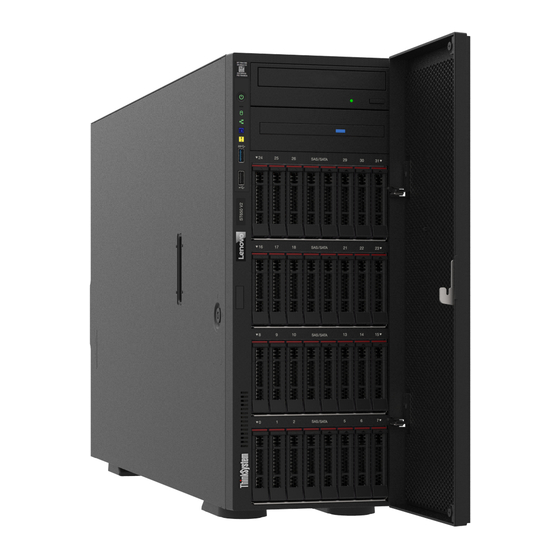
- Page 28 Optical-drive bays 1-2 Foot stands 2.5-inch hot-swap drive bays 24-31 Front panel For information about the controls, connectors, and status LEDs on the front panel, see “Front panel” on page 21. Drive activity LED (green) ThinkSystem ST650 V2 Setup Guide...
-
Page 29: Front Panel
Each hot-swap drive comes with an activity LED. When this LED is flashing, it indicates that the drive is in use. Drive status LED (yellow) These LEDs are on SAS or SATA hard disk drives and solid-state drives, and indicate the following status: Lit: The drive has failed. - Page 30 System error LED (yellow) Simple-swap drive activity LED (green) USB 3.2 Gen 1 connector Network activity LED (green) USB 2.0 connector with Lenovo XClarity Controller management System ID button with system ID LED (blue) Power button with power status LED (green) Press this button to turn the server on and off manually.
- Page 31 Each time you press the system ID button, the state of both the system ID LEDs changes. The LEDs can be changed to on, blinking, or off. You can also use the Lenovo XClarity Controller or a remote management program to change the state of the system ID LEDs to assist in visually locating the server among other servers.
-
Page 32: Rear View
Install power supply units to these bays, connect them to power cords. Make sure the power cords are connected properly. You can purchase a power supply option from Lenovo and install the power supply to provide power redundancy without turning off the server. -
Page 33: Rear View Leds
Press this button to force a nonmaskable interrupt to the processor. You might have to use a pen or the end of a straightened paper clip to press the button. You can also use it to force a blue-screen memory dump. Use this button only when you are directed to do so by Lenovo Support. 10Gb Ethernet connector Used to attach a 10Gb Ethernet cable. - Page 34 Each time you press the system ID button on the front panel, the state of both the system ID LEDs changes. The LEDs can be changed to on, blinking, or off. You can also use the Lenovo XClarity Controller or a remote management program to change the state of the system ID LEDs to assist in visually locating the server among other servers.
-
Page 35: External Lcd Diagnostics Handset
Ethernet status LED Color Status Description Ethernet link LED Green Network link is established. None Network link is disconnected. Ethernet activity LED Green Blinking Network link is connected and active. None The server is disconnected from a LAN. External LCD diagnostics handset The external LCD diagnostics handset is an external device that is connected to the server with a cable, and it allows quick access to system information such as errors, system status, firmware, network, and health information. - Page 36 The diagnostics device consists of an LCD display and 5 navigation buttons. LCD display Scroll buttons (up/down/left/right) Press the scroll buttons to locate and select system information. Select button Press the select button to select from the options in the menu. ThinkSystem ST650 V2 Setup Guide...
- Page 37 Option flow diagram The external LCD diagnostics handset displays various system information. Navigate through the options with the scroll keys. Chapter 2 Server components...
- Page 38 • Possible sources of the error Configuration Error System VPD Information Example Sub Menu Machine Type: xxxx • Machine type and serial number Serial Num: xxxxxx • Universal Unique ID (UUID) Universal Unique ID: xxxxxxxxxxxxxxxxxxxxxxxxxxxx ThinkSystem ST650 V2 Setup Guide...
- Page 39 System Firmware Sub Menu Example UEFI UEFI (Inactive) • Firmware level (status) Build: D0E101P • Build ID Version: 1.00 • Version number Date: 2019-12-26 • Release date XCC Primary XCC Primary (Active) • Firmware level (status) Build: DVI399T • Build ID Version: 4.07 •...
-
Page 40: System Board Components
• Modify XCC Static IPv4 Address/Net mask/ Gateway • Modify System Name • Generate/Download FFDC Service Data • Remove FPGA Test Image System board components The illustration in this section shows the component locations on the system board. ThinkSystem ST650 V2 Setup Guide... - Page 41 Figure 11. System board components Table 10. Components on the system board CMOS battery connector SATA 0-3 connector PCIe 2 connector SATA 8-11 connector PCIe 1 connector Internal USB connector 3 Operator-information-panel connector Internal USB connector 4 Power distribution board signal connector /TCM connector (for Chinese Mainland only) Power distribution board power connector...
-
Page 42: System Board Leds
Off: No power supply is properly installed, or the LED itself has failed. Flashing rapidly (four times per second): The server is turned off and is not ready to be turned on. The power-control button is disabled. This will last approximately 5 to 10 seconds. ThinkSystem ST650 V2 Setup Guide... -
Page 43: System Board Switches
• LED blinking: the system is functioning properly, and no action is necessary. • LED not blinking: (trained technician only) replace the system board. See “System board replacement” in the ThinkSystem ST650 V2 Maintenance Manual. XCC heartbeat LED (green) This LED indicates XCC heartbeat and boot process: •... - Page 44 On: dump UEFI debug message to serial port. BMC Remote debug Keeping this switch in the off position enables BMC remote debug. ME security override Changing this switch to the On position disables ME Security checks. ThinkSystem ST650 V2 Setup Guide...
-
Page 45: Server Locks
Table 14. SW3 switch block definition Default Switch Description Definition position number Force BMC and CPU Changing this switch to the On position forces BMC and CPU reset reset. Power permission Changing this switch to the Off position ignores Power override Permission and allows the system to power-on. -
Page 46: Backplates And Backplanes
Use the section to understand the internal connectors on the backplate or the backplane you use. 2.5-inch drive backplanes Use this information to locate the connectors on the 2.5-inch drive backplanes. 2.5-inch SAS/SATA 8-bay backplane SAS/SATA connector Power connector Figure 15. 2.5-inch SAS/SATA 8-bay backplane connectors ThinkSystem ST650 V2 Setup Guide... -
Page 47: 3.5-Inch Drive Backplanes
2.5-inch SAS/SATA/NVMe and NVMe 8-bay backplane NVMe 6-7 connector NVMe 4-5 connector SAS/SATA connector Power connector NVMe 2-3 connector NVMe 0-1 connector Figure 16. 2.5-inch SAS/SATA/NVMe and NVMe 8-bay backplane connectors 3.5-inch drive backplanes Use this information to locate the connectors on the 3.5-inch drive backplanes. 3.5-inch SAS/SATA 4-bay backplane Power connector SAS/SATA connector... -
Page 48: 3.5-Inch Drive Backplate
Use this information to locate the connectors on the 3.5-inch drive backplate. 3.5-inch SAS/SATA 4-bay backplate Signal cable Power cable Figure 19. 3.5-inch SAS/SATA 4-bay backplate cables Power distribution board connectors Use this information to locate the connectors on the power distribution board connectors. ThinkSystem ST650 V2 Setup Guide... -
Page 49: Parts List
Figure 20. Connectors on the power distribution board Table 15. Connectors on the power distribution board PDB signal connector BP 3 power connector Main power connector BP 2 power connector BP 1 power connector GPU 3 power connector GPU 1 power connector ODD power connector GPU 2 power connector PSU 2 power connector... - Page 50 Tier 1 CRU at your request with no service agreement, you will be charged for the installation. • Tier 2 customer replaceable unit (CRU): You may install a Tier 2 CRU yourself or request Lenovo to install it, at no additional charge, under the type of warranty service that is designated for your server.
- Page 51 For more information about ordering the parts shown in Figure 21 “Server components” on page 42: 1. Go to and navigate to the support page for your server. http://datacentersupport.lenovo.com 2. Click Parts. Power distribution board √ Power distribution board cover √...
- Page 52 NVLink bridge √ Full-length GPU adapter √ PCIe adapter √ Fan module √ Fan filler √ Intrusion switch √ External LCD diagnostics handset √ PCIe adapter holder √ Fan cage √ Redundant power supply unit √ ThinkSystem ST650 V2 Setup Guide...
-
Page 53: Power Cords
Several power cords are available, depending on the country and region where the server is installed. To view the power cords that are available for the server: 1. Go to: http://dcsc.lenovo.com/#/ 2. Click Preconfigured Model or Configure to order. 3. Enter the machine type and model for your server to display the configurator page. - Page 54 ThinkSystem ST650 V2 Setup Guide...
-
Page 55: Chapter 3. Internal Cable Routing
• Ensure that the cable is not pinched and does not cover any connectors or obstruct any components on the system board. • Ensure that the relevant cables pass through the cable clips and guides. Figure 22. Cable clips and guides on 2.5-inch chassis © Copyright Lenovo 2021... -
Page 56: Backplane And Backplate Cable Routing
Any damage to the cable sockets might require replacing the system board. Backplane and backplate cable routing For more information about the backplane and backplate cable routing, see ThinkSystem ST650 V2 Backplane/Backplate Cable Routing Guide. -
Page 57: Front Usb Cable Routing
Figure 24. Cable routing for front panel Front USB cable routing Use the section to understand the cable routing for the front USB. From Rear of front panel System board: Front USB connector Notes: ↔ ↔ ↔ ↔ • Connections between connectors; , ... -
Page 58: Gpu Cable Routing
System board: CFF RAID power connector Notes: ↔ ↔ ↔ ↔ • Connections between connectors; , ... • When routing the cables, ensure that all cables are routed appropriately through the cable guides and cable clips. ThinkSystem ST650 V2 Setup Guide... -
Page 59: M.2 Boot Adapter Cable Routing
Figure 27. Cable routing for the CFF RAID adapter M.2 boot adapter cable routing Use the section to understand the cable routing for the M.2 boot adapter. From M.2 power connector on the M.2 boot adapter System board: M.2 power connector M.2 signal connector on the M.2 boot adapter System board: M.2 signal connector Notes:... -
Page 60: Optical Drive Cable Routing
System board: PCIe 4 connector Notes: ↔ ↔ ↔ ↔ • Connections between connectors; , ... • When routing the cables, ensure that all cables are routed appropriately through the cable guides and cable clips. ThinkSystem ST650 V2 Setup Guide... -
Page 61: Power Distribution Board Cable Routing
Figure 30. Cable routing to enable PCIe slot 8 Power distribution board cable routing Use the section to understand the cable routing for the power distribution board. From Power distribution board: Main power connector System board: Power distribution board power connector Power distribution board: PDB signal connector System board: Power distribution board signal connector Notes:... -
Page 62: Tape Drive Cable Routing
• The following illustrations show the cable routing for PCIe slot 1 and 9 respectively, the routing for the other PCIe slots are similar. Figure 32. Cable routing for SAS tape drive to PCIe slot 1 ThinkSystem ST650 V2 Setup Guide... - Page 63 Figure 33. Cable routing for SAS tape drive to PCIe slot 9 USB tape drive From Power connector on tape drive Power distribution board: ODD power connector Signal connector on tape drive System board: Internal USB connector 4 Notes: ↔ ↔...
- Page 64 ThinkSystem ST650 V2 Setup Guide...
-
Page 65: Chapter 4. Server Hardware Setup
Validate that the server hardware was set up successfully. See “Validate server setup” on page 149. 3. Configure the system. a. Connect the Lenovo XClarity Controller to the management network. See “Set the network connection for the Lenovo XClarity Controller” on page 151. -
Page 66: Installation Guidelines
Go to to download firmware updates for your server. ThinkSystem ST650 V2 Drivers and Software Important: Some cluster solutions require specific code levels or coordinated code updates. If the component is part of a cluster solution, verify that the latest level of code is supported for the cluster solution before you update the code. -
Page 67: Safety Inspection Checklist
Click the Power tab to see all line cords. • Make sure that the insulation is not frayed or worn. 3. Check for any obvious non-Lenovo alterations. Use good judgment as to the safety of any non-Lenovo alterations. 4. Check inside the server for any obvious unsafe conditions, such as metal filings, contamination, water or other liquid, or signs of fire or smoke damage. -
Page 68: System Reliability Guidelines
Attention: Prevent exposure to static electricity, which might lead to system halt and loss of data, by keeping static-sensitive components in their static-protective packages until installation, and handling these devices with an electrostatic-discharge wrist strap or other grounding system. • Limit your movement to prevent building up static electricity around you. ThinkSystem ST650 V2 Setup Guide... -
Page 69: Technical Rules
• Take additional care when handling devices during cold weather, for heating would reduce indoor humidity and increase static electricity. • Always use an electrostatic-discharge wrist strap or other grounding system. • While the device is still in its static-protective package, touch it to an unpainted metal surface on the outside of the server for at least two seconds. -
Page 70: Technical Rules For Memory Modules
• The following table includes all the feasible combinations of different types of DIMMs: Table 17. DIMM compatibility DIMM Types RDIMM PMEMs RDIMM PMEMs See the following to locate the DIMM slots and corresponding channels. ThinkSystem ST650 V2 Setup Guide... - Page 71 Figure 35. Processor and memory module layout Table 18. Channel and slot information of DIMMs around processor Memory Controller 2 Controller 3 Controller 1 Controller 0 controllers Channels Channel Channel Channel Channel Channel Channel Channel Channel 1 (F) 1 (E) 1 (H) 0 (G) 0 (C)
- Page 72 Table 20. Independent memory mode with one processor and different capacity memory modules Processor 1 Total Total DIMMs DIMMs Notes: 1. DIMM configurations that support Sub NUMA Clustering (SNC), which can be enabled via UEFI. ThinkSystem ST650 V2 Setup Guide...
- Page 73 2. DIMM configurations that support Software Guard Extensions (SGX), see “Enable Software Guard Extensions (SGX)” on page 157 to enable this feature. Independent memory mode with two processors and same capacity memory modules Table 21. Independent mode with two processors and same capacity memory modules (processor 1) Processor 1 Total Total...
- Page 74 Note: When adding one or more DIMMs during a memory upgrade, you might need to remove some DIMMs that are already installed to new locations. Mirror memory mode with one processor Table 25. Mirror mode with one processor Processor 1 Total Total DIMMs DIMMs ThinkSystem ST650 V2 Setup Guide...
- Page 75 Note: DIMM configurations with an asterisk (*) listed in the table support the Sub NUMA Clustering (SNC) feature, which can be enabled via UEFI. SNC is not supported if DIMM population does not follow the sequence indicated by the table above. Mirror memory mode with two processors Table 26.
- Page 76 • All the DRAM DIMMs that are installed must be of the same type, rank, and capacity with minimum capacity of 16 GB. It is recommended to use Lenovo DRAM DIMMs with the same part number. • All Platinum, Gold, and Intel Xeon ICX Silver 4313 16c 135W 2.3GHz processors will support Intel Optane Persistent Memory 200 Series (PMEMs).
- Page 77 Go to System Configuration and Boot Management ➙ System Settings ➙ Intel Optane PMEMs to configure and manage PMEMs. • Lenovo XClarity Essentials OneCLI Some management options are available in commands that are executed in the path of Lenovo XClarity Essentials OneCLI in the operating system. See https://sysmgt.lenovofiles.com/help/topic/toolsctr_cli_ to learn how to download and use Lenovo XClarity Essentials lenovo/onecli_t_download_use_tcscli.html...
- Page 78 App Direct capacity of PMEMs requires the following steps before it is truly available for applications. 1. Namespaces must be created for region capacity allocation. 2. Filesystem must be created and formatted for the namespaces in the operating system. ThinkSystem ST650 V2 Setup Guide...
- Page 79 Each App Direct region can be allocated into one namespace. Create namespaces in the following operating systems: – Windows: Use powershell command. To create a namespace, use Windows Server 2019 or later versions. – Linux: Use ndctl command. – VMware: Reboot the system, and VMware will create namespaces automatically. After creating namespaces for App Direct capacity allocation, make sure to create and format filesystem in the operating system so that the App Direct capacity is accessible for applications.
- Page 80 In the case the passphrases are lost or forgotten, the stored data cannot be backed up or restored, but you can contact Lenovo service for administrative secure erase. • After three failed unlocking attempts, the corresponding PMEMs enter “exceeded” state with a system warning message, and the PMEM unit can only be unlocked after the system is rebooted.
- Page 81 (for both Linux and Windows). ipmctl delete -pcd Notes: See the following links to learn how to download and use impctl in different operating systems: • Windows: https://datacentersupport.lenovo.com/us/en/videos/YTV101407 • Linux: https://datacentersupport.lenovo.com/us/en/solutions/HT508642 5. Reboot the system. App Direct Mode In this mode, PMEMs act as independent and persistent memory resources directly accessible by specific applications, and DRAM DIMMs act as system memory.
- Page 82 In this mode, PMEMs act as volatile system memory, while DRAM DIMMs act as cache. Note: When adding one or more DIMMs during a memory upgrade, you might need to remove some DIMMs that are already installed to new locations. ThinkSystem ST650 V2 Setup Guide...
- Page 83 Memory Mode with one processor Table 31. Memory Mode with one processor • D1: 16 GB RDIMM • D2: 16 GB RDIMM or 32 GB RDIMM • P: 128 GB Persistent Memory Module (PMEM) Processor 1 Configuration 4 PMEMs and 4 DIMMs 4 PMEMs and 8 DIMMs...
- Page 84 Table 36. Mixed Memory Mode with two processors (processor 2) Processor 2 Configuration 2 PMEMs and 16 DIMMs* 8 PMEMs and 16 DIMMs 16 PMEMs and 16 DIMMs Note: * Not-interleaved mode only. Does not support 100% interleaved mode. ThinkSystem ST650 V2 Setup Guide...
-
Page 85: Technical Rules For Pcie Slots
Technical rules for PCIe slots PCIe adapters must be installed in a specific order based on the CPU configuration that you implement on your server. Installation priority Component PCIe slot priorities Double-wide GPU One processor installed: 1, 3 Two processor installed: 1, 3, 7, 5 Retimer One processor installed: 1, 3 Two processor installed: 7, 5, 1, 3... - Page 86 1. Supports one CPU with TDP less than 205W. 2. PMEM is not supported. 3. GPU adapters are not supported. 4. Supports up to thirty-two 2.5-inch SAS/SATA drives. 5. Supports up to sixteen 3.5-inch SAS/SATA drives. 6. Fan redundancy is not supported. ThinkSystem ST650 V2 Setup Guide...
- Page 87 Table 38. One processor fan configuration (continued) Fan configuration Description Four dual rotor fans in fan slot 1, 2, 3, and 4. 1. Supports one CPU with TDP less than 250W. 2. Supports PMEM. 3. GPU adapters are not supported. 4.
-
Page 88: Install Server Hardware Options
Installation procedures are presented in the optimum sequence to minimize work. Install a hot-swap power supply Use this information to install a hot-swap power supply. About this task S001 ThinkSystem ST650 V2 Setup Guide... - Page 89 DANGER Electrical current from power, telephone, and communication cables is hazardous. To avoid a shock hazard: • Connect all power cords to a properly wired and grounded electrical outlet/source. • Connect any equipment that will be attached to this product to properly wired outlets/sources. •...
- Page 90 – If you are replacing the existing power supply with a new power supply of different wattage, attach the power information label that comes with this option onto the existing label near the power supply. Figure 37. Hot-swap power supply label ThinkSystem ST650 V2 Setup Guide...
-
Page 91: Remove The Front Door
在直流输入状态下,若电源供应器插座不支持热插拔功能,请务必不要对设备电源线进行热插拔,此操作可能 导致设备损坏及数据丢失。因错误执行热插拔导致的设备故障或损坏,不属于保修范围。 NEVER CONNECT AND DISCONNECT THE POWER SUPPLY CABLE AND EQUIPMENT WHILE YOUR EQUIPMENT IS POWERED ON WITH DC SUPPLY (hot-plugging). Otherwise you may damage the equipment and result in data loss, the damages and losses result from incorrect operation of the equipment will not be covered by the manufacturers’... -
Page 92: Remove The Server Cover
Open the front door. Lift the front door slightly upward until you can completely remove it. After you finish Remove the server cover Use this information to remove the server cover. About this task S014 CAUTION: ThinkSystem ST650 V2 Setup Guide... - Page 93 Hazardous voltage, current, and energy levels might be present. Only a qualified service technician is authorized to remove the covers where the label is attached. S017 CAUTION: Hazardous moving fan blades nearby. Keep fingers and other body parts away. S033 CAUTION: Hazardous energy present.
-
Page 94: Remove The Front Bezel
• Prevent exposure to static electricity, which might lead to system halt and loss of data, by keeping static- sensitive components in their static-protective packages until installation, and handling these devices with an electrostatic-discharge wrist strap or other grounding system. ThinkSystem ST650 V2 Setup Guide... -
Page 95: Remove A Flash Power Module
• If the server is in a rack, remove it from the rack. • If foot stands are installed on the server, rotate them inwards and lay the server on its side for easier operation. Watch the procedure. A video of the installation and removal process is available: •... - Page 96 Watch the procedure. A video of the installation and removal process is available: • YouTube: https://youtube.com/playlist?list=PLYV5R7hVcs-DoEcxrm2zKNpaKOdZ3f8Qc • Youku: https://list.youku.com/albumlist/show/id_59636516 Procedure Step 1. Disconnect the cable of the flash power module from the RAID adapter. Step 2. Remove the flash power module. ThinkSystem ST650 V2 Setup Guide...
-
Page 97: Remove The Air Baffle
Figure 43. Flash power module removal Gently pivot the retaining clip as shown. Lift the flash power module up and remove it from the holder. Remove the air baffle Follow this procedure to remove the air baffle. About this task S033 CAUTION: Hazardous energy present. -
Page 98: Remove An Nvlink Bridge
The power-control button on the device and the power switch on the power supply do not turn off the electrical current supplied to the device. The device also might have more than one power cord. To ThinkSystem ST650 V2 Setup Guide... - Page 99 remove all electrical current from the device, ensure that all power cords are disconnected from the power source. Attention: • Read “Installation guidelines” on page 58 to ensure that you work safely. • Power off the server and disconnect all power cords for this task. •...
-
Page 100: Remove A Full-Length Gpu Adapter
• If the server is in a rack, remove it from the rack. • If foot stands are installed on the server, rotate them inwards and lay the server on its side for easier operation. Notes: ThinkSystem ST650 V2 Setup Guide... -
Page 101: Remove A Hot-Swap Fan
• Depending on the specific type, your full-length GPU adapter might look different from the illustration in this topic. • Use any documentation that comes with the full-length GPU adapter and follow those instructions in addition to the instructions in this topic. Watch the procedure. -
Page 102: Remove The Fan Cage Assembly
Pinch on the top of the fan, and press on the latch to release the fan from the connector. Lift the fan out from the fan cage. Remove the fan cage assembly Use this procedure to remove the fan cage assembly. About this task ThinkSystem ST650 V2 Setup Guide... - Page 103 S002 CAUTION: The power-control button on the device and the power switch on the power supply do not turn off the electrical current supplied to the device. The device also might have more than one power cord. To remove all electrical current from the device, ensure that all power cords are disconnected from the power source.
-
Page 104: Remove The Expansion Drive Cage
Watch the procedure. A video of the installation and removal process is available: • YouTube: https://youtube.com/playlist?list=PLYV5R7hVcs-DoEcxrm2zKNpaKOdZ3f8Qc • Youku: https://list.youku.com/albumlist/show/id_59636516 Procedure Step 1. Disconnect all the cables from the backplane. Step 2. Remove the expansion drive cage. Figure 50. Expansion drive cage removal ThinkSystem ST650 V2 Setup Guide... -
Page 105: Install The Optical Drive Cage
Lift and hold the blue retention tab. Carefully pull the expansion drive cage at the same time to slide it out of the opening in the chassis. Install the optical drive cage Use this information to install the optical drive cage. About this task S002 CAUTION:... -
Page 106: Install An Optical Drive Or A Tape Drive
• Prevent exposure to static electricity, which might lead to system halt and loss of data, by keeping static- sensitive components in their static-protective packages until installation, and handling these devices with an electrostatic-discharge wrist strap or other grounding system. ThinkSystem ST650 V2 Setup Guide... - Page 107 Note: The following illustrations are based on the scenario that you install an optical drive. The procedure is similar for installing a tape drive. Watch the procedure. A video of the installation and removal process is available: • YouTube: https://youtube.com/playlist?list=PLYV5R7hVcs-DoEcxrm2zKNpaKOdZ3f8Qc •...
- Page 108 Step 3. Remove the retainer from the chassis. Figure 54. Drive retainer removal Step 4. Install the retainer to only the left side of the optical drive or tape drive. Figure 55. Optical drive retainer installation ThinkSystem ST650 V2 Setup Guide...
-
Page 109: Install The 5.25-Inch Drive Bay Adapter
Step 5. Hold the optical drive or tape drive in the correct orientation; then, slide it into the drive bay until it snaps into position. Figure 56. Optical drive installation Step 6. Connect the power cable and the signal cable to the rear of the optical drive or tape drive. See “Optical drive cable routing”... - Page 110 Watch the procedure. A video of the installation and removal process is available: • YouTube: https://youtube.com/playlist?list=PLYV5R7hVcs-DoEcxrm2zKNpaKOdZ3f8Qc • Youku: https://list.youku.com/albumlist/show/id_59636516 Procedure Step 1. If necessary, remove the cover of the drive bay filler from the front bezel. ThinkSystem ST650 V2 Setup Guide...
- Page 111 Figure 57. Drive bay filler cover installation Push the tab on the front bezel to release the cover of the drive bay filler. Remove the cover of the drive bay filler as shown. Step 2. If necessary, remove the drive bay filler out of the chassis. Figure 58.
-
Page 112: Install A 2.5-Inch Hot-Swap Drive
For more information about the cable routing. See “Optical drive cable routing” on page Install a 2.5-inch hot-swap drive backplane Use this information to install a 2.5-inch hot-swap drive backplane. About this task S002 ThinkSystem ST650 V2 Setup Guide... -
Page 113: Install A 3.5-Inch Hot-Swap Drive
CAUTION: The power-control button on the device and the power switch on the power supply do not turn off the electrical current supplied to the device. The device also might have more than one power cord. To remove all electrical current from the device, ensure that all power cords are disconnected from the power source. -
Page 114: Install A 3.5-Inch Simple-Swap Drive
Slide the backplane as shown until it is seated into position in the drive cage. Figure 62. Installation of the 3.5-inch hot-swap drive backplane Install a 3.5-inch simple-swap drive backplate Use this information to install a 3.5-inch simple-swap drive backplate. About this task ThinkSystem ST650 V2 Setup Guide... - Page 115 Figure 63. Installation of the 3.5-inch hot-swap drive backplate Step 3. Connect the power cable and the signal cable to the system board. See “3.5-inch simple-swap drive backplate cable routing” in the ThinkSystem ST650 V2 Backplane/Backplate Cable Routing Guide. Chapter 4...
-
Page 116: Install A 2.5-Inch Drive Into A 3.5-Inch Drive
Align the two screw holes in the drive with the corresponding holes in the drive adapter; then, install the two screws to secure the drive to the drive adapter. Figure 64. 2.5-inch drive installation to drive adapter ThinkSystem ST650 V2 Setup Guide... -
Page 117: Install A Simple-Swap Drive
The following notes describe the type of drives that your server supports and other information that you must consider when you install a drive. • For a complete list of supported optional devices for the server, see: https://static.lenovo.com/us/en/ serverproven/index.shtml Chapter 4... - Page 118 Description activity LED The simple-swap drive is active. Solid on Green None The simple-swap drive is not active. 4. Use the Lenovo XClarity Provisioning Manager to configure the RAID if necessary. For more information, see: ThinkSystem ST650 V2 Setup Guide...
-
Page 119: Install A Hot-Swap Drive
The following notes describe the type of drives that your server supports and other information that you must consider when you install a drive. • For a complete list of supported optional devices for the server, see: https://static.lenovo.com/us/en/ serverproven/index.shtml • The drive bays are numbered to indicate the installation order (starting from number “0”). Follow the installation order when you install a drive. -
Page 120: Install The Internal Cff Adapter
Blinking yellow (blinking rapidly, about The RAID adapter is locating the drive. four flashes per second) 4. Use the Lenovo XClarity Provisioning Manager to configure the RAID if necessary. For more information, see: http://sysmgt.lenovofiles.com/help/index.jsp?topic=%2FLXPM%2FRAID_setup.html Install the internal CFF adapter Use this information to install the internal CFF RAID adapter, internal CFF HBA adapter, or internal CFF RAID expander adapter. - Page 121 CAUTION: The power-control button on the device and the power switch on the power supply do not turn off the electrical current supplied to the device. The device also might have more than one power cord. To remove all electrical current from the device, ensure that all power cords are disconnected from the power source.
-
Page 122: Install A Processor-Heat-Sink Module
Connect the cables to the CFF adapter. See “Internal CFF RAID adapter cable routing” on page 50. Install a processor-heat-sink module The processor and heat sink are removed together as part of a processor-heat-sink-module (PHM) assembly. PHM installation requires a Torx T30 driver. About this task S002 ThinkSystem ST650 V2 Setup Guide... - Page 123 CAUTION: The power-control button on the device and the power switch on the power supply do not turn off the electrical current supplied to the device. The device also might have more than one power cord. To remove all electrical current from the device, ensure that all power cords are disconnected from the power source.
- Page 124 See “Update the firmware” on page 152. • Installing an additional PHM can change the memory requirements for your system. See “Technical rules for memory modules” in the ThinkSystem ST650 V2 Setup Guide for a list of processor-to-memory relationships. The following illustration shows the components of the PHM.
-
Page 125: Install A Memory Module
• YouTube: https://youtube.com/playlist?list=PLYV5R7hVcs-DoEcxrm2zKNpaKOdZ3f8Qc • Youku: https://list.youku.com/albumlist/show/id_59636516 Procedure Step 1. Remove the processor socket cover, if one is installed on the processor socket, by placing your fingers in the half-circles at each end of the cover and lifting it from the system board. Step 2. - Page 126 Locate the required memory module slot on the system board. Note: Ensure that you observe the installation rules and sequence in “Technical rules for memory modules” in the ThinkSystem ST650 V2 Setup Guide. Step 3. Install the memory module into the slot.
-
Page 127: Install The M.2 Boot Adapter
Figure 74. Memory module installation Open the retaining clip on each end of the memory module slot. Attention: To avoid breaking the retaining clips or damaging the memory module slots, open and close the clips gently. Align the memory module with the slot, and gently place the memory module on the slot with both hands. - Page 128 Step 2. Connect the cables to the M.2 boot adapter. Figure 76. M.2 signal cable screw installation Connect all the cables. Tighten the screw that secures the M.2 signal cable to the M.2 boot adapter. ThinkSystem ST650 V2 Setup Guide...
-
Page 129: Adjust The Retainer On The M.2 Boot
Step 3. Connect the power cable and the signal cable to the system board. See “M.2 boot adapter cable routing” on page 51. Adjust the retainer on the M.2 boot adapter Use this information to adjust the retainer on the M.2 boot adapter. About this task S002 CAUTION:... -
Page 130: Install An M.2 Drive
• Prevent exposure to static electricity, which might lead to system halt and loss of data, by keeping static- sensitive components in their static-protective packages until installation, and handling these devices with an electrostatic-discharge wrist strap or other grounding system. Locate the M.2 drive slot on the M.2 adapter. ThinkSystem ST650 V2 Setup Guide... -
Page 131: Install The Intrusion Switch
Note: For some M.2 adapters that support two identical M.2 drives, install the M.2 drive in slot 0 first. Figure 78. M.2 drive slot Table 41. M.2 drive slot locations on M.2 boot adapter M.2 boot adapter slot 0 M.2 boot adapter slot 1 Watch the procedure. - Page 132 Then, push the intrusion switch in until it is securely seated. Figure 80. Intrusion switch installation Step 2. Connect the intrusion switch cable to the system board. See “System board components” on page ThinkSystem ST650 V2 Setup Guide...
-
Page 133: Install The Fan Cage Assembly
Install the fan cage assembly Use this procedure to install the fan cage assembly. About this task S002 CAUTION: The power-control button on the device and the power switch on the power supply do not turn off the electrical current supplied to the device. The device also might have more than one power cord. To remove all electrical current from the device, ensure that all power cords are disconnected from the power source. -
Page 134: Install A Hot-Swap Fan
Note: Ensure that you observe the installation rules and sequence in “Technical rules for system fans” on page 77. Step 2. Align the fan over the fan slot in the fan cage assembly. Step 3. Insert the fan into the fan cage assembly until it clicks into place. ThinkSystem ST650 V2 Setup Guide... -
Page 135: Install A Pcie Adapter Holder
Figure 82. Hot-swap fan installation Install a PCIe adapter holder Use this information to install a PCIe adapter holder. About this task S002 CAUTION: The power-control button on the device and the power switch on the power supply do not turn off the electrical current supplied to the device. -
Page 136: Install A Pcie Adapter
• Use any documentation that comes with the PCIe adapter and follow those instructions in addition to the instructions in this topic. Watch the procedure. A video of the installation and removal process is available: • YouTube: https://youtube.com/playlist?list=PLYV5R7hVcs-DoEcxrm2zKNpaKOdZ3f8Qc ThinkSystem ST650 V2 Setup Guide... -
Page 137: Install A Full-Length Gpu Adapter
• Youku: https://list.youku.com/albumlist/show/id_59636516 Procedure Step 1. Locate the applicable PCIe slot. See “Specifications” on page 3 to identify the different types of PCIe slots in your server. Note: Ensure that you observe the installation rules and sequence in “Technical rules for PCIe slots”... - Page 138 If a bracket is installed in the PCIe slot, remove it. Store the bracket for the PCIe slot in case that you later remove the PCIe adapter and need the bracket to cover the place. Step 5. Install the full-length GPU adapter. ThinkSystem ST650 V2 Setup Guide...
-
Page 139: Install An Nvlink Bridge
Figure 85. Full-length GPU adapter installation Note: Make sure the PCIe adapter retainer is in the opened position. Connect the power cable to the full-length GPU adapter. Align the full-length GPU adapter to the PCIe adapter holder and the PCIe slot; then, gently press both ends of the full-length GPU adapter until it is securely seated in the PCIe slot. - Page 140 Watch the procedure. A video of the installation and removal process is available: • YouTube: https://youtube.com/playlist?list=PLYV5R7hVcs-DoEcxrm2zKNpaKOdZ3f8Qc • Youku: https://list.youku.com/albumlist/show/id_59636516 Procedure Step 1. Remove the NVLink covers. Figure 86. NVLink covers removal Step 2. Note the orientation of the NVLink bridge; then, install the NVLink bridge as shown. ThinkSystem ST650 V2 Setup Guide...
-
Page 141: Install A Gpu Filler
Figure 87. NVLink bridge installation Install a GPU filler Use this information to install a GPU filler. About this task S033 CAUTION: Hazardous energy present. Voltages with hazardous energy might cause heating when shorted with metal, which might result in spattered metal, burns, or both. S017 CAUTION: Hazardous moving fan blades nearby. -
Page 142: Install A T4 Filler
Hazardous moving fan blades nearby. Keep fingers and other body parts away. S033 CAUTION: Hazardous energy present. Voltages with hazardous energy might cause heating when shorted with metal, which might result in spattered metal, burns, or both. Attention: ThinkSystem ST650 V2 Setup Guide... - Page 143 • Read “Installation guidelines” on page 58 to ensure that you work safely. • Prevent exposure to static electricity, which might lead to system halt and loss of data, by keeping static- sensitive components in their static-protective packages until installation, and handling these devices with an electrostatic-discharge wrist strap or other grounding system.
-
Page 144: Install The Air Baffle
• Prevent exposure to static electricity, which might lead to system halt and loss of data, by keeping static- sensitive components in their static-protective packages until installation, and handling these devices with an electrostatic-discharge wrist strap or other grounding system. ThinkSystem ST650 V2 Setup Guide... -
Page 145: Install A Flash Power Module
Watch the procedure. A video of the installation and removal process is available: • YouTube: https://youtube.com/playlist?list=PLYV5R7hVcs-DoEcxrm2zKNpaKOdZ3f8Qc • Youku: https://list.youku.com/albumlist/show/id_59636516 Procedure Step 1. Make sure that all cables inside the server have been properly routed so that they will not interfere with the air baffle. - Page 146 Flash power module slot 2 Flash power module slot 4 Watch the procedure. A video of the installation and removal process is available: • YouTube: https://youtube.com/playlist?list=PLYV5R7hVcs-DoEcxrm2zKNpaKOdZ3f8Qc • Youku: https://list.youku.com/albumlist/show/id_59636516 Procedure Step 1. Install the flash power module. ThinkSystem ST650 V2 Setup Guide...
-
Page 147: Install The Front Bezel
Figure 93. Flash power module installation Note the orientation of the flash power module; then, gently insert the flash power module into the retaining clip at one side as shown. Press the flash power module down on the other side until it snaps into place. Step 2. -
Page 148: Install The Front Door
Watch the procedure. A video of the installation and removal process is available: • YouTube: https://youtube.com/playlist?list=PLYV5R7hVcs-DoEcxrm2zKNpaKOdZ3f8Qc • Youku: https://list.youku.com/albumlist/show/id_59636516 Procedure Step 1. Install the front door. ThinkSystem ST650 V2 Setup Guide... -
Page 149: Install The Server Cover
Figure 95. Front door installation Align the two hooks on the front door with the corresponding holes in the front bezel; then, move the front door inward and then pull it slightly downward until it is secured in place by the hooks. - Page 150 The service label is free of charge. Watch the procedure. A video of the installation and removal process is available: • YouTube: https://youtube.com/playlist?list=PLYV5R7hVcs-DoEcxrm2zKNpaKOdZ3f8Qc • Youku: https://list.youku.com/albumlist/show/id_59636516 Procedure Step 1. Install the server cover. ThinkSystem ST650 V2 Setup Guide...
-
Page 151: Install The Foot Stands
Figure 96. Server cover installation Note: Before you slide the cover forward, ensure that all the tabs of the cover engage the chassis correctly. If all the tabs do not engage the chassis correctly, it will be very difficult to remove the cover later. - Page 152 Figure 97. Foot stand installation Step 2. For each foot stand, rotate the foot stand outwards. Figure 98. Foot stand adjustment Important: To help the server stand steadily, ensure that the foot stands are rotated outward. ThinkSystem ST650 V2 Setup Guide...
-
Page 153: Install The Tower To Rack Conversion Kit
Install the tower to rack conversion kit This section includes instructions on how to install the tower to rack conversion kit. Install the EIA brackets Step 1. If foot stands are installed on your tower server, lay the server on its side and remove them first. For each foot stand, rotate the foot stand inwards. - Page 154 Align the holes in the right EIA bracket with the corresponding holes on the top of the chassis; then, use a screwdriver to reinstall the three screws that you removed to secure the right EIA bracket. ThinkSystem ST650 V2 Setup Guide...
-
Page 155: Install The Rail And Latch Covers
Figure 103. Installing right EIA bracket Step 5. Align the holes in the left EIA bracket with the corresponding holes on the bottom of the chassis; then, use a screwdriver to install the three screws to secure the left EIA bracket. Figure 104. -
Page 156: Cable The Server
Connect the server to any storage devices. Power on the server After the server performs a short self-test (power status LED flashes quickly) when connected to input power, it enters a standby state (power status LED flashes once per second). ThinkSystem ST650 V2 Setup Guide... -
Page 157: Validate Server Setup
Power off the server The server remains in a standby state when it is connected to a power source, allowing the Lenovo XClarity Controller to respond to remote power-on requests. To remove all power from the server (power-on LED off), you must disconnect all power cables. - Page 158 ThinkSystem ST650 V2 Setup Guide...
-
Page 159: Chapter 5. System Configuration
The following methods are available to set the network connection for the Lenovo XClarity Controller if you are not using DHCP: • If a monitor is attached to the server, you can use Lenovo XClarity Controller to set the network connection. -
Page 160: Set The Front Usb 2.0 Connector For Lenovo Xclarity Controller Connection
Step 2. When you see <F1> Setup, press F1 to open up the Lenovo XClarity Provisioning Manager V3 Go to LXPM V3 ➙ UEFI Setup ➙ BMC Settings to specify how the Lenovo XClarity Controller will Step 3. connect to the network. - Page 161 Machine-type-specific firmware-only UXSPs are also available. See the following table to determine the best Lenovo tool to use for installing and setting up the firmware: Note: The server UEFI settings for option ROM must be set to Auto or UEFI to update firmware using Lenovo XClarity Administrator or Lenovo XClarity Essentials.
- Page 162 The latest firmware can be found at the following site: http://datacentersupport.lenovo.com/us/en/products/servers/thinksystem/st650v2/7Z74/downloads • Lenovo XClarity Provisioning Manager V3 From Lenovo XClarity Provisioning Manager V3, you can update the Lenovo XClarity Controller firmware, the UEFI firmware, and the Lenovo XClarity Provisioning Manager V3 software. ThinkSystem ST650 V2 Setup Guide...
- Page 163 • Lenovo XClarity Controller If you need to install a specific update, you can use the Lenovo XClarity Controller interface for a specific server. Notes: – To perform an in-band update through Windows or Linux, the operating system driver must be installed and the Ethernet-over-USB (sometimes called LAN over USB) interface must be enabled.
-
Page 164: Configure The Firmware
Several options are available to install and set up the firmware for the server. Important: Do not configure option ROMs to be set to Legacy unless directed to do so by Lenovo Support. This setting prevents UEFI drivers for the slot devices from loading, which can cause negative side effects for Lenovo software, such as Lenovo XClarity Administrator and Lenovo XClarity Essentials OneCLI, and to the Lenovo XClarity Controller. -
Page 165: Memory Configuration
Specific details about updating firmware using Lenovo XClarity Administrator are available at: http://sysmgt.lenovofiles.com/help/topic/com.lenovo.lxca.doc/server_configuring.html • Lenovo XClarity Controller You can configure the management processor for the server through the Lenovo XClarity Controller Web interface or through the command-line interface. For information about configuring the server using Lenovo XClarity Controller, see: http://sysmgt.lenovofiles.com/help/topic/com.lenovo.systems.management.xcc.doc/NN1ia_c_... -
Page 166: Raid Configuration
OS logical drives or volumes. An introduction to RAID is available at the following Lenovo Press website: https://lenovopress.com/lp0578-lenovo-raid-introduction Detailed information about RAID management tools and resources is available at the following Lenovo Press website: https://lenovopress.com/lp0579-lenovo-raid-management-tools-and-resources Notes: •... -
Page 167: Back Up The Server Configuration
Alternatively, you can use the s s a a v v e e command from Lenovo XClarity Essentials OneCLI to create a backup of all configuration settings. For more information about the s s a a v v e e command, see: http://sysmgt.lenovofiles.com/help/topic/toolsctr_cli_lenovo/onecli_r_save_command.html... -
Page 168: Uuid
2. Copy and unpack the OneCLI package, which also includes other required files, to the server. Make sure that you unpack the OneCLI and the required files to the same directory. 3. After you have Lenovo XClarity Essentials OneCLI in place, type the following command to set the UUID: onecli config set SYSTEM_PROD_DATA.SysInfoUUID <uuid_value>... -
Page 169: Update The Asset Tag
4. Update the asset tag information. • From Lenovo XClarity Essentials OneCLI Lenovo XClarity Essentials OneCLI sets the asset tag in the Lenovo XClarity Controller. Select one of the following methods to access the Lenovo XClarity Controller and set the asset tag: –... - Page 170 Note: BMC, IMM, or XCC internal LAN/USB IP address, account name, and password are all valid for this command. Example command is as follows: onecli config set SYSTEM_PROD_DATA.SysEncloseAssetTag <asset_tag> −−bmc xcc_user_id:xcc_password@xcc_external_ip 4. Reset the Lenovo XClarity Controller to the factory defaults. Go to https://sysmgt.lenovofiles.com/help/ for more information. topic/com.lenovo.systems.management.xcc.doc/NN1ia_c_resettingthexcc.html ThinkSystem ST650 V2 Setup Guide...
-
Page 171: Chapter 6. Resolving Installation Issues
• “Displayed system memory is less than installed physical memory” on page 165 • “A Lenovo optional device that was just installed does not work.” on page 166 • “Voltage planar fault is displayed in the event log” on page 166... - Page 172 • Replace the affected backplane signal cable. • Replace the affected backplane. 8. Run the diagnostics tests for the hard disk drives. When you start a server and press F1, the Lenovo XClarity Provisioning Manager V3 interface is displayed by default. You can perform hard drive diagnostics from this interface.
- Page 173 • If a memory module was disabled by the user or by POST, reseat the memory module; then, run the Setup utility and enable the memory module. 4. Run memory diagnostics. When you start a solution and press F1, the Lenovo XClarity Provisioning Manager V3 interface is displayed by default. You can perform memory diagnostics with this interface.
- Page 174 2 (if installed) to verify that the problem is not the processor or the memory module connector. 8. (Trained technician only) Replace the system board. A Lenovo optional device that was just installed does not work. 1. Check the XCC event log for any events associated with the device.
-
Page 175: Appendix A. Getting Help And Technical Assistance
Appendix A. Getting help and technical assistance If you need help, service, or technical assistance or just want more information about Lenovo products, you will find a wide variety of sources available from Lenovo to assist you. On the World Wide Web, up-to-date information about Lenovo systems, optional devices, services, and support are available at: http://datacentersupport.lenovo.com... -
Page 176: Collecting Service Data
Collecting service data To clearly identify the root cause of a server issue or at the request of Lenovo Support, you might need collect service data that can be used for further analysis. Service data includes information such as event logs and hardware inventory. -
Page 177: Contacting Support
Lenovo XClarity Essentials OneCLI has inventory application to collect service data. It can run both in- band and out-of-band. When running in-band within the host operating system on the server, OneCLI can collect information about the operating system, such as the operating system event log, in addition to the hardware service data. - Page 178 ThinkSystem ST650 V2 Setup Guide...
-
Page 179: Appendix B. Trademarks
Appendix B. Trademarks LENOVO, THINKSYSTEM, Flex System, System x, NeXtScale System, and x Architecture are trademarks of Lenovo. Intel and Intel Xeon are trademarks of Intel Corporation in the United States, other countries, or both. Internet Explorer, Microsoft, and Windows are trademarks of the Microsoft group of companies. - Page 180 ThinkSystem ST650 V2 Setup Guide...
-
Page 181: Index
USB power distribution board configure for XCC management tape drive front view cable the server collecting service data Common installation issues Configuration - ThinkSystem ST650 V2 configure the firmware connector gaseous contamination drive backplane Getting help drive backplate GPU adapter... - Page 182 Lenovo Capacity Planner power on the server Lenovo XClarity Essentials power status LED Lenovo XClarity Provisioning Manager V3 processor option install processor-heat-sink module option install M.2 boot adapter installing M.2 drive ThinkSystem ST650 V2 Setup Guide...
- Page 183 LED QR code system board switches and jumpers System configuration - ThinkSystem ST650 V2 system error LED 21, 34 system ID button system ID LED 21, 34 system power LED rear view system reliability guidelines...
- Page 184 ThinkSystem ST650 V2 Setup Guide...
Need help?
Do you have a question about the ThinkSystem ST650 V2 and is the answer not in the manual?
Questions and answers