Lenovo ThinkSystem ST250 V2 Maintenance Manual
Hide thumbs
Also See for ThinkSystem ST250 V2:
- Quick start (2 pages) ,
- Setup manual (140 pages) ,
- Reference (200 pages)
Table of Contents
Advertisement
Quick Links
Advertisement
Table of Contents

Related Manuals for Lenovo ThinkSystem ST250 V2


Summary of Contents for Lenovo ThinkSystem ST250 V2
- Page 1 ThinkSystem ST250 V2 Maintenance Manual Machine Types: 7D8F and 7D8G...
- Page 2 Before using this information and the product it supports, be sure to read and understand the safety information and the safety instructions, which are available at: http://thinksystem.lenovofiles.com/help/topic/safety_documentation/pdf_files.html In addition, ensure that you are familiar with the terms and conditions of the Lenovo warranty for your server, which can be found at: http://datacentersupport.lenovo.com/warrantylookup First Edition (March 2022) ©...
-
Page 3: Table Of Contents
Fixed power supply ... . . Install the front system fan ..115 Redundant power supplies ..© Copyright Lenovo 2022... - Page 4 Install the hot-swap power supply ..179 Appendix B. Getting help and Processor replacement ... . 184 technical assistance ..239 ThinkSystem ST250 V2 Maintenance Manual...
- Page 5 Index ....247 Important notes ....244 © Copyright Lenovo 2022...
- Page 6 ThinkSystem ST250 V2 Maintenance Manual...
-
Page 7: Safety
Vor der Installation dieses Produkts die Sicherheitshinweise lesen. Prima di installare questo prodotto, leggere le Informazioni sulla Sicurezza. Les sikkerhetsinformasjonen (Safety Information) før du installerer dette produktet. Antes de instalar este produto, leia as Informações sobre Segurança. © Copyright Lenovo 2022... -
Page 8: Safety Inspection Checklist
1 & IEC 60950-1, the standard for Safety of Electronic Equipment within the Field of Audio/Video, Information Technology and Communication Technology. Lenovo assumes you are qualified in the servicing of equipment and trained in recognizing hazards energy levels in products. - Page 9 Click Power ➙ Power Cables to see all line cords. • Make sure that the insulation is not frayed or worn. 3. Check for any obvious non-Lenovo alterations. Use good judgment as to the safety of any non-Lenovo alterations.
- Page 10 ThinkSystem ST250 V2 Maintenance Manual viii...
-
Page 11: Chapter 1. Introduction
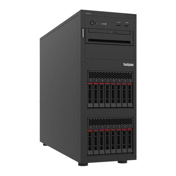
Chapter 1. Introduction The ThinkSystem ST250 V2 server is a 4U tower server designed for performance and expansion for various IT workloads. With the modular design, the server is flexible to be customized for maximum storage capacity or high storage density with selectable input/output options and tiered system management. - Page 12 Scan the QR code with a mobile device and a QR code reader application to get quick access to the Lenovo Service web site for this server. The Lenovo Service web site provides additional information for parts installation and replacement videos, and error codes for server support.
-
Page 13: Server Form Factor
Figure 3. QR code Server form factor The ThinkSystem ST250 V2 server is designed to support both tower and rack form factors. You can change the server from tower form factor to rack form factor by installing the tower-to-rack conversion kit. For instructions on how to install the tower-to-rack conversion kit, refer to the documentation that comes with the conversion kit. - Page 14 – Optical/tape drive bays • Optical-drive bay 1 (lower bay) supports one of the following: – Optical drive – Tape drive (RDX or LTO) • Optical-drive bay 2 (upper bay) supports one optional optical drive ThinkSystem ST250 V2 Maintenance Manual...
- Page 15 – One Video Graphics Array (VGA) connector – One serial connector – One Lenovo XClarity Controller network connector – Two Ethernet connectors (shared with Lenovo XClarity Controller network connector) – Four USB 3.2 Gen 2 (10Gb) connectors • Two 1Gbps RJ45 with BCM 5720 Network •...
- Page 16 • High range: 200 to 240 Vac • Input frequency range: 50 to 60 Hz Note: ThinkSystem ST250 V2 only supports AC input power. Do not use 240 VDC input. Depending on your configuration, the server comes with one of the following power...
- Page 17 – M.2 drives, 10/25GbE Ethernet adapters, and redundant power supplies should not be installed in this configuration. The ThinkSystem ST250 V2 server complies with ASHRAE Class A2 specifications. Environment Depending on the hardware configurations, some models comply with ASHRAE Class A3 and A4 specifications.
-
Page 18: Particulate Contamination
If Lenovo determines that the levels of particulates or gases in your environment have caused damage to the device, Lenovo may condition provision of repair or replacement of devices or parts on implementation of appropriate remedial measures to mitigate such environmental contamination. -
Page 19: Firmware Updates
• Best practices related to updating firmware is available at the following site: – http://lenovopress.com/LP0656 • The latest firmware can be found at the following site: – http://datacentersupport.lenovo.com/us/en/products/servers/thinksystem/st250v2/7D8F/downloads • You can subscribe to product notification to stay up to date on firmware updates: – https://datacentersupport.lenovo.com/tw/en/solutions/ht509500 Chapter 1... - Page 20 Hat Enterprise Linux (RHEL) and SUSE Linux Enterprise Server (SLES) operating system distributions. Machine-type-specific firmware-only UXSPs are also available. Firmware updating tools See the following table to determine the best Lenovo tool to use for installing and setting up the firmware: Tool Update...
- Page 21 LXPM in this document, unless specified otherwise. To see the LXPM version supported by your server, go to https://sysmgt.lenovofiles.com/help/topic/lxpm_frontend/lxpm_product_page.html • Lenovo XClarity Controller If you need to install a specific update, you can use the Lenovo XClarity Controller interface for a specific server. Notes: Chapter 1...
- Page 22 – If you update firmware through the Lenovo XClarity Controller, make sure that you have downloaded and installed the latest device drivers for the operating system that is running on the server. For specific details about updating firmware using Lenovo XClarity Controller, see: “Updating Server Firmware”...
-
Page 23: Tech Tips
Power off the server The server remains in a standby state when it is connected to a power source, allowing the Lenovo XClarity Controller to respond to remote power-on requests. To remove all power from the server (power-on LED off), you must disconnect all power cables. - Page 24 Note: The Lenovo XClarity Controller can place the server in a standby state as an automatic response to a critical system failure. • Start an orderly shutdown using the operating system (if supported by your operating system). • Press the power-on button to start an orderly shutdown (if supported by your operating system).
-
Page 25: Chapter 2. Server Components
This section provides information that helps locate the server components. Identifying your server When you contact Lenovo for help, the machine type, model, and serial number information helps support technicians to identify your server and provide faster service. The model number and serial number are on the ID label on the front of the server. The following illustration shows the location of the ID label containing the machine type, model, and serial number. - Page 26 The system service label on the inside of the server cover provides a QR code for mobile access to service information. You can scan the QR code with a mobile device for quick access to additional information including parts installation, replacement, and error codes. The following illustration shows the QR code. ThinkSystem ST250 V2 Maintenance Manual...
-
Page 27: Front View
Figure 6. Location of QR code Front view The front view of the server varies by model. The following illustration shows the server components that may appear on the front of this server model. Chapter 2 Server components... - Page 28 Optical/tape Eight 2.5-inch Optical/tape Optical/tape drives drives drives hot-swap drives Optical/tape drives Optical-drive bay Optical-drive bay Optical-drive bay Optical-drive bay 2: Optical drive 2: Optical drive 2: Optical drive 2: Optical drive ThinkSystem ST250 V2 Maintenance Manual...
-
Page 29: Front Panel
Optical-drive bay Optical-drive bay Optical-drive bay Optical-drive bay 1: Optical/tape 1: Optical/tape 1: Optical/tape 1: Optical/tape drive drive drive drive Three SATA drives Two SATA drives Four SAS/SATA Eight SAS/SATA Eight SAS/SATA (Bay 4, 5, 6) and (Bay 4, 5) drives (Bay 4 to 7) drives (Bay 8 to 15) drives (Bay 4 to 11) - Page 30 ID button, the state of the system ID LED changes. The LED can be changed to on, blinking, or off. You can also use the Lenovo XClarity Controller or a remote management program to change the state of the system ID LED to assist in visually locating the server among other servers.
-
Page 31: Side View
Status Color Description Action Yellow An error has been detected on the server. Check the event log to determine the exact Causes might include one or more of the cause of the error. following errors: • The temperature of the server reached the non-critical temperature threshold. -
Page 32: Rear View
Processor and heat sink Front system fan 2 Rear system fan RAID flash power module holder DIMM slots Rear view Use this information to locate the connectors and components on the rear of the server. ThinkSystem ST250 V2 Maintenance Manual... - Page 33 Rear view of server models with a fixed power Rear view of server models with two hot-swap supply power supplies Figure 9. Rear view Table 6. Components on the rear of server models with a fixed power supply or two hot-swap power supplies Power cord connector Ethernet connector 2 VGA connector...
-
Page 34: Rear View Leds
There are four PCIe slots on the system board to install appropriate PCIe adapters. For information about the PCIe slots, see “Specifications” on page 3. Rear view LEDs The illustration in this section shows the LEDs on the rear the server. ThinkSystem ST250 V2 Maintenance Manual... - Page 35 Figure 10. Rear view LEDs of the server Table 7. LEDs on the rear of the server Callout Callout Ethernet link LED (green) Power output LED (green) Ethernet activity LED (green) Power supply error LED (yellow) Power input LED (green) Ethernet status LEDs Each network connector has two status LEDs.
- Page 36 LED is off, replace the power supply. Power supply error LED • Off: The power supply is working normally. • Yellow: The power supply has failed. To resolve the issue, replace the power supply. ThinkSystem ST250 V2 Maintenance Manual...
-
Page 37: System-Board Components
System-board components The illustration in this section shows the component locations on the system board. Figure 11. System board components Table 8. Components on the system board Callout Callout Rear fan connector SATA 4 Front VGA connector Fan 4 connector for front fan Processor power connector TPM/TCM connector DIMM Slot 1... -
Page 38: System-Board Led
The illustration in this section shows the location of the jumpers and buttons on the server. Note: If there is a clear protective sticker on the top of the switch blocks, you must remove and discard it to access the switches. ThinkSystem ST250 V2 Maintenance Manual... - Page 39 • Pins 2 and 3: Override the power-on permission. Force Lenovo XClarity Controller update • Pins 1 and 2: Normal (default). jumper • Pins 2 and 3: Force the Lenovo XClarity Controller to update to the latest version. Clear CMOS jumper • Pins 1 and 2: Normal (default).
-
Page 40: Drive Backplates/Backplanes
3.5-inch simple-swap backplate (Bay 0-3) Table 11. 3.5-inch simple-swap backplate (Bay 0-3) Bay number in the lower drive cage Signal/SATA connector SATA 3 Signal/SATA connector SATA 2 Signal/SATA connector SATA 1 Signal/SATA connector SATA 0 ThinkSystem ST250 V2 Maintenance Manual... - Page 41 3.5-inch simple-swap backplate (Bay 4-7 without optical disk drive) Table 12. 3.5-inch simple-swap backplate (Bay 4-7 without optical disk drive) Bay number in the lower drive cage Signal/SATA connector SATA 7 Signal/SATA connector SATA 6 Signal/SATA connector SATA 5 Signal/SATA connector SATA 4 3.5-inch simple-swap backplate (Bay 4-5 with optical disk drive) Table 13.
-
Page 42: Power Distribution Board
The illustrations in this section identify the connectors on the power distribution boards. Two types of power distribution boards are supported by this server: • “Power distribution board for the fixed power supply” on page 33 • “Power distribution board for hot-swap power supplies” on page 33 ThinkSystem ST250 V2 Maintenance Manual... - Page 43 Power distribution board for the fixed power supply Figure 14. Power distribution board for the fixed power supply Table 16. Power distribution board for the fixed power supply Power supply system power connector System power connector Power supply processor power connector Processor power connector Power distribution board for hot-swap power supplies Figure 15.
-
Page 44: Raid Adapters
• “9350-16i” on page 34 • “4350/5350-8i” on page 35 9350-8i Figure 16. 9350-8i connectors Table 18. 9350-8i connectors RAID flash power module connector 9350-16i Figure 17. 9350-8i connectors Table 19. 9350-8i connectors RAID flash power module connector ThinkSystem ST250 V2 Maintenance Manual... -
Page 45: Server Locks
4350/5350-8i Figure 18. 4350/5350-8i connectors Server locks Locking the server cover prevents unauthorized access to the inside of your server. Locking the front door (available on some models) prevents unauthorized access to the installed drives. Padlock Your server comes with a padlock loop. When a padlock is installed, the server cover cannot be removed. Figure 19. - Page 46 The cable lock also locks the server cover. This is the same type of lock used with many notebook computers. You can order such a cable lock directly from Lenovo by searching for Kensington at: http://www.lenovo.com/support...
-
Page 47: Internal Cable Routing
Internal cable routing Some of the components in the server come with internal cables meant for specific connectors. Before connecting the cables, read the following guidelines carefully: • Turn off the server before you connect or disconnect any internal cables. •... -
Page 48: Front Panel
Fan 4 connector for front fan Heat sink fan Fan 2 connector for processor Front panel Use the section to understand the cable routing for the front panel. Note: Ensure that all cables are routed through the correct cable clips. ThinkSystem ST250 V2 Maintenance Manual... - Page 49 Figure 23. Cable routing for the front panel Cable From Operator-information-panel Front panel Front-panel connector on the system board cable USB cable Front panel Front USB connector on the system board Chapter 2 Server components...
-
Page 50: M.2 Adapter, Intrusion Switch, And Raid Flash Power Module
RAID flash power module RAID adapter cable Intrusion switch Intrusion switch connector on the Intrusion switch cable system board Optical/tape drives Use this section to understand the cable routing for server models with optical/tape drives. ThinkSystem ST250 V2 Maintenance Manual... -
Page 51: Fixed Power Supply
From ODD/tape drive power connector on the system ODD/Tape drive power connectors board ODD/Tape drive SATA connectors SATA 6, 7 Fixed power supply Use the section to understand the cable routing for the fixed power supply. Notes: • Ensure that all cables are routed through the correct cable clips. •... - Page 52 Processor power connector on the fixed power power cable power connector supply Processor power cable Processor power connector Processor power connector on the system board System power cable System power connector System power connector on the system board ThinkSystem ST250 V2 Maintenance Manual...
-
Page 53: Redundant Power Supplies
Redundant power supplies Use the section to understand the cable routing for the redundant power supplies. Note: Ensure that all cables are routed through the correct cable clips Figure 25. Cable routing for the redundant power supplies Cable From (power distribution board) Processor power Processor power connector Processor power connector on the system... -
Page 54: Simple-Swap Drives
• “Six 3.5-inch SATA drives with ODD/tape drives” on page Four 3.5-inch simple-swap drives Use this section to understand the cable routing for server models with four 3.5-inch simple-swap drives (software RAID). From Backplane 1 power connector Lower backplate SATA 0-3 ThinkSystem ST250 V2 Maintenance Manual... - Page 55 Eight 3.5-inch simple-swap drives Use this section to understand the cable routing for server models with eight 3.5-inch simple-swap drives (software RAID). Following are the options available for this configuration: • “Eight SATA drives” on page 45 • “Seven SATA drives and one NVMe drive” on page 46 Eight SATA drives From From...
- Page 56 SATA 4, 5, 6, and MCIO x4 connector for NVMe Six 3.5-inch simple-swap drives with ODD/tape drives Use this section to understand the cable routing for server models with six 3.5-inch simple-swap drives and ODD/tape drives (software RAID). ThinkSystem ST250 V2 Maintenance Manual...
- Page 57 From From Backplane 1 power Backplane 2 power connector connector Upper backplate SATA 4, 5 SATA 0-3 ODD/tape drive power Lower backplate ODD/Tape drive power connector on the connectors system board ODD/Tape drive SATA SATA 6, 7 connectors Chapter 2 Server components...
-
Page 58: Hot-Swap Drives
Use this section to understand the cable routing for server models with four 3.5-inch hot-swap drives. Following are the options available for this configuration: • “Software RAID” on page 49 • “One 8i RAID adapter” on page 50 ThinkSystem ST250 V2 Maintenance Manual... - Page 59 Software RAID From Lower backplane power connector Backplane 1 power connector Lower backplane SAS/SATA connector SATA 0-3 Chapter 2 Server components...
- Page 60 One 8i RAID adapter From Lower backplane power connector Backplane 1 power connector Lower backplane SAS/SATA connector ThinkSystem ST250 V2 Maintenance Manual...
- Page 61 Eight 3.5-inch hot-swap drives Use this section to understand the cable routing for server models with eight 3.5-inch hot-swap drives. • “Software RAID” on page 51 • “One 8i RAID adapter” on page 52 Software RAID From Lower backplane power connector Backplane 1 power connector Upper backplane SAS/SATA connector SATA 4, 5, 6, 7...
- Page 62 Lower backplane SAS/SATA connector Eight 2.5-inch hot-swap drives Use this section to understand the cable routing for server models with eight 2.5-inch hot-swap drives. • “Software RAID” on page 53 • “One 8i RAID adapter” on page 54 ThinkSystem ST250 V2 Maintenance Manual...
- Page 63 Software RAID From Lower backplane power connector Backplane 1 power connector Lower backplane SAS/SATA 1 connector SATA 4, 5, 6, 7 Lower backplane SAS/SATA 0 connector SATA 0-3 Lower backplane SGPIO1 connector Chapter 2 Server components...
- Page 64 Sixteen 2.5-inch hot-swap drives Use this section to understand the cable routing for server models with sixteen 2.5-inch hot-swap drives. • “One 9350-16i RAID adapter” on page 55 • “Two 4350/5350-8i RAID adapters” on page 56 ThinkSystem ST250 V2 Maintenance Manual...
- Page 65 One 9350-16i RAID adapter From Lower backplane power connector Backplane 1 power connector Lower backplane SAS/SATA 1 connector Lower backplane SAS/SATA 0 connector Upper backplane power connector Backplane 2 power connector Upper backplane SAS/SATA 1 connector Upper backplane SAS/SATA 0 connector Chapter 2 Server components...
- Page 66 Use this section to understand the cable routing for server models with four 3.5-inch and eight 2.5-inch hot- swap drives. • “One 9350-16i RAID adapter” on page 57 • “Two 4350/5350-8i RAID adapters” on page 58 ThinkSystem ST250 V2 Maintenance Manual...
- Page 67 One 9350-16i RAID adapter From Lower backplane power connector Backplane 1 power connector Lower backplane SAS/SATA connector Upper backplane power connector Backplane 2 power connector Upper backplane SAS/SATA 1 connector Upper backplane SAS/SATA 0 connector Chapter 2 Server components...
-
Page 68: Parts List
Use the parts list to identify each of the components that are available for your server. For more information about ordering the parts shown in Figure 26 “Server components” on page 59: http://datacentersupport.lenovo.com/us/en/products/servers/thinksystem/st250v2/7D8F/parts Note: Depending on the model, your server might look slightly different from the illustration. ThinkSystem ST250 V2 Maintenance Manual... - Page 69 Tier 1 CRU at your request with no service agreement, you will be charged for the installation. • Tier 2 customer replaceable unit (CRU): You may install a Tier 2 CRU yourself or request Lenovo to install it, at no additional charge, under the type of warranty service that is designated for your server.
- Page 70 2.5-inch hot-swap drive backplane √ Front bezel √ Front door √ 2.5-inch to 3.5-inch drive adapter √ 3.5-inch drive filler √ 3.5-inch drive carrier √ 3.5-inch drive √ 3.5-inch drive cage √ 3.5-inch hot-swap drive backplane √ ThinkSystem ST250 V2 Maintenance Manual...
- Page 71 Table 21. Parts listing (continued) Consumable Description Index Tier 1 CRU Tier 2 CRU Structural parts 3.5-inch simple-swap drive backplate √ 3.5-inch simple-swap drive backplate √ with ODD PCIe adapter √ Rear system fan √ Chassis √ Memory module √ RAID flash power module holder √...
-
Page 72: Power Cords
The cord set should have the appropriate safety approvals for the country in which the equipment will be installed. • Power cords for a specific country or region are usually available only in that country or region. ThinkSystem ST250 V2 Maintenance Manual... -
Page 73: Chapter 3. Internal Cable Routing
2. When installing the front system fan into the chassis, make sure the cables do not interfere with the two posts and the fan is firmly seated. Fan power cable Use the section to understand the internal routing and connectors for the fan power cables. © Copyright Lenovo 2022... -
Page 74: Front Panel
Fan 4 connector for front fan Heat sink fan Fan 2 connector for processor Front panel Use the section to understand the cable routing for the front panel. Note: Ensure that all cables are routed through the correct cable clips. ThinkSystem ST250 V2 Maintenance Manual... - Page 75 Figure 28. Cable routing for the front panel Cable From Operator-information-panel Front panel Front-panel connector on the system board cable USB cable Front panel Front USB connector on the system board Chapter 3 Internal cable routing...
-
Page 76: M.2 Adapter, Intrusion Switch, And Raid Flash Power Module
RAID flash power module RAID adapter cable Intrusion switch Intrusion switch connector on the Intrusion switch cable system board Optical/tape drives Use this section to understand the cable routing for server models with optical/tape drives. ThinkSystem ST250 V2 Maintenance Manual... -
Page 77: Fixed Power Supply
From ODD/tape drive power connector on the system ODD/Tape drive power connectors board ODD/Tape drive SATA connectors SATA 6, 7 Fixed power supply Use the section to understand the cable routing for the fixed power supply. Notes: • Ensure that all cables are routed through the correct cable clips. •... - Page 78 Processor power connector on the fixed power power cable power connector supply Processor power cable Processor power connector Processor power connector on the system board System power cable System power connector System power connector on the system board ThinkSystem ST250 V2 Maintenance Manual...
-
Page 79: Redundant Power Supplies
Redundant power supplies Use the section to understand the cable routing for the redundant power supplies. Note: Ensure that all cables are routed through the correct cable clips Figure 30. Cable routing for the redundant power supplies Cable From (power distribution board) Processor power Processor power connector Processor power connector on the system... -
Page 80: Simple-Swap Drives
• “Six 3.5-inch SATA drives with ODD/tape drives” on page Four 3.5-inch simple-swap drives Use this section to understand the cable routing for server models with four 3.5-inch simple-swap drives (software RAID). From Backplane 1 power connector Lower backplate SATA 0-3 ThinkSystem ST250 V2 Maintenance Manual... -
Page 81: Eight 3.5-Inch Simple-Swap Drives
Eight 3.5-inch simple-swap drives Use this section to understand the cable routing for server models with eight 3.5-inch simple-swap drives (software RAID). Following are the options available for this configuration: • “Eight SATA drives” on page 71 • “Seven SATA drives and one NVMe drive” on page 72 Eight SATA drives From From... -
Page 82: Six 3.5-Inch Simple-Swap Drives With Odd/Tape Drives
SATA 4, 5, 6, and MCIO x4 connector for NVMe Six 3.5-inch simple-swap drives with ODD/tape drives Use this section to understand the cable routing for server models with six 3.5-inch simple-swap drives and ODD/tape drives (software RAID). ThinkSystem ST250 V2 Maintenance Manual... - Page 83 From From Backplane 1 power Backplane 2 power connector connector Upper backplate SATA 4, 5 SATA 0-3 ODD/tape drive power Lower backplate ODD/Tape drive power connector on the connectors system board ODD/Tape drive SATA SATA 6, 7 connectors Chapter 3 Internal cable routing...
-
Page 84: Hot-Swap Drives
Use this section to understand the cable routing for server models with four 3.5-inch hot-swap drives. Following are the options available for this configuration: • “Software RAID” on page 75 • “One 8i RAID adapter” on page 76 ThinkSystem ST250 V2 Maintenance Manual... - Page 85 Software RAID From Lower backplane power connector Backplane 1 power connector Lower backplane SAS/SATA connector SATA 0-3 Chapter 3 Internal cable routing...
- Page 86 One 8i RAID adapter From Lower backplane power connector Backplane 1 power connector Lower backplane SAS/SATA connector ThinkSystem ST250 V2 Maintenance Manual...
-
Page 87: Eight 3.5-Inch Hot-Swap Drives
Eight 3.5-inch hot-swap drives Use this section to understand the cable routing for server models with eight 3.5-inch hot-swap drives. • “Software RAID” on page 77 • “One 8i RAID adapter” on page 78 Software RAID From Lower backplane power connector Backplane 1 power connector Upper backplane SAS/SATA connector SATA 4, 5, 6, 7... -
Page 88: Eight 2.5-Inch Hot-Swap Drives
Lower backplane SAS/SATA connector Eight 2.5-inch hot-swap drives Use this section to understand the cable routing for server models with eight 2.5-inch hot-swap drives. • “Software RAID” on page 79 • “One 8i RAID adapter” on page 80 ThinkSystem ST250 V2 Maintenance Manual... - Page 89 Software RAID From Lower backplane power connector Backplane 1 power connector Lower backplane SAS/SATA 1 connector SATA 4, 5, 6, 7 Lower backplane SAS/SATA 0 connector SATA 0-3 Lower backplane SGPIO1 connector Chapter 3 Internal cable routing...
-
Page 90: Sixteen 2.5-Inch Hot-Swap Drives
Sixteen 2.5-inch hot-swap drives Use this section to understand the cable routing for server models with sixteen 2.5-inch hot-swap drives. • “One 9350-16i RAID adapter” on page 81 • “Two 4350/5350-8i RAID adapters” on page 82 ThinkSystem ST250 V2 Maintenance Manual... - Page 91 One 9350-16i RAID adapter From Lower backplane power connector Backplane 1 power connector Lower backplane SAS/SATA 1 connector Lower backplane SAS/SATA 0 connector Upper backplane power connector Backplane 2 power connector Upper backplane SAS/SATA 1 connector Upper backplane SAS/SATA 0 connector Chapter 3 Internal cable routing...
-
Page 92: Drives
Use this section to understand the cable routing for server models with four 3.5-inch and eight 2.5-inch hot- swap drives. • “One 9350-16i RAID adapter” on page 83 • “Two 4350/5350-8i RAID adapters” on page 84 ThinkSystem ST250 V2 Maintenance Manual... - Page 93 One 9350-16i RAID adapter From Lower backplane power connector Backplane 1 power connector Lower backplane SAS/SATA connector Upper backplane power connector Backplane 2 power connector Upper backplane SAS/SATA 1 connector Upper backplane SAS/SATA 0 connector Chapter 3 Internal cable routing...
- Page 94 Backplane 1 power connector Lower backplane SAS/SATA connector C0, Slot 2 Upper backplane power connector Backplane 2 power connector Upper backplane SAS/SATA 1 connector C1, Slot 4 Upper backplane SAS/SATA 0 connector C0, Slot 4 ThinkSystem ST250 V2 Maintenance Manual...
-
Page 95: Chapter 4. Hardware Replacement Procedures
Go to to download firmware updates for your server. ThinkSystem ST250 V2 Drivers and Software Important: Some cluster solutions require specific code levels or coordinated code updates. If the component is part of a cluster solution, verify that the latest level of code is supported for the cluster solution before you update the code. -
Page 96: Safety Inspection Checklist
1 & IEC 60950-1, the standard for Safety of Electronic Equipment within the Field of Audio/Video, Information Technology and Communication Technology. Lenovo assumes you are qualified in the servicing of equipment and trained in recognizing hazards energy levels in products. -
Page 97: System Reliability Guidelines
Click Power ➙ Power Cables to see all line cords. • Make sure that the insulation is not frayed or worn. 3. Check for any obvious non-Lenovo alterations. Use good judgment as to the safety of any non-Lenovo alterations. -
Page 98: Handling Static-Sensitive Devices
The power-control button on the device and the power switch on the power supply do not turn off the electrical current supplied to the device. The device also might have more than one power cord. ThinkSystem ST250 V2 Maintenance Manual... - Page 99 To remove all electrical current from the device, ensure that all power cords are disconnected from the power source. Attention: • Read the “Installation guidelines” on page 85 to ensure that you work safely. • Turn off the server and peripheral devices, and disconnect the power cords and all external cables (see “Power off the server”...
- Page 100 Figure 32. Removing the drive cage Step 4. Remove the backplane or backplate (see “Remove the 3.5-inch/2.5-inch hot-swap drive backplane” on page 92 or “Remove the 3.5-inch simple-swap drive backplate” on page 96). After this task is completed ThinkSystem ST250 V2 Maintenance Manual...
-
Page 101: Install The 3.5-Inch/2.5-Inch Drive Cage
If you are instructed to return the component or optional device, follow all packaging instructions, and use any packaging materials for shipping that are supplied to you. Install the 3.5-inch/2.5-inch drive cage Follow instructions in this section to install the 3.5-inch/2.5-inch drive cage. About this task To avoid potential danger, read and follow the following safety statements. -
Page 102: 3.5-Inch/2.5-Inch Hot-Swap Drive Backplane Replacement
The power-control button on the device and the power switch on the power supply do not turn off the electrical current supplied to the device. The device also might have more than one power cord. ThinkSystem ST250 V2 Maintenance Manual... - Page 103 To remove all electrical current from the device, ensure that all power cords are disconnected from the power source. Attention: • Read the “Installation guidelines” on page 85 to ensure that you work safely. • Turn off the server and peripheral devices, and disconnect the power cords and all external cables (see “Power off the server”...
- Page 104 Figure 35. Removing the hot-swap drive backplane After this task is completed If you are instructed to return the component or optional device, follow all packaging instructions, and use any packaging materials for shipping that are supplied to you. ThinkSystem ST250 V2 Maintenance Manual...
-
Page 105: Install The 3.5-Inch/2.5-Inch Hot-Swap Drive Backplane
Install the 3.5-inch/2.5-inch hot-swap drive backplane Follow instructions in this section to install the 3.5-inch/2.5-inch hot-swap drive backplane. About this task To avoid potential danger, read and follow the following safety statements. • S002 CAUTION: The power-control button on the device and the power switch on the power supply do not turn off the electrical current supplied to the device. -
Page 106: 3.5-Inch Simple-Swap Drive Backplate Replacement
Remove the server cover (see “Remove the server cover” on page 199). Remove the front door (see “Remove the front door” on page 124). Remove the front bezel (see “Remove the front bezel” on page 122). ThinkSystem ST250 V2 Maintenance Manual... - Page 107 Remove all of the installed simple-swap drives and drive bay fillers from the drive cage and set them aside on a static-protective surface (see “Remove a simple-swap drive” on page 106 or “Remove a 2.5-inch drive from a 3.5-inch drive bay” on page 110). Remove the system fan (see “Remove the front system fan”...
-
Page 108: Install The 3.5-Inch Simple-Swap Drive
• Touch the static-protective package that contains the component to any unpainted metal surface on the server; then, remove it from the package and place it on a static-protective surface. Watch the procedure A video of this procedure is available at YouTube: https://youtube.com/playlist?list=PLYV5R7hVcs- DoEcxrm2zKNpaKOdZ3f8Qc Procedure ThinkSystem ST250 V2 Maintenance Manual... -
Page 109: Cmos Battery (Cr2032) Replacement
Step 1. Position the backplate on the drive cage so that the tabs on the drive cage are inserted into the corresponding slots on the backplate. Step 2. Close the plunger to secure the backplate in place. Figure 39. Installing the simple-swap drive backplate After this task is completed 1. - Page 110 • S004 CAUTION: When replacing the lithium battery, use only Lenovo specified part number or an equivalent type battery recommended by the manufacturer. If your system has a module containing a lithium battery, replace it only with the same module type made by the same manufacturer. The battery contains lithium and can explode if not properly used, handled, or disposed of.
-
Page 111: Install The Cmos Battery (Cr2032)
• S004 CAUTION: When replacing the lithium battery, use only Lenovo specified part number or an equivalent type battery recommended by the manufacturer. If your system has a module containing a lithium battery, replace it only with the same module type made by the same manufacturer. The battery contains lithium and can explode if not properly used, handled, or disposed of. -
Page 112: Drive Replacement
2. Reconfigure the server and reset the system date, time and passwords. Drive replacement Follow instructions in this section to remove and install drives. Remove a hot-swap drive Follow instructions in this section to remove a hot-swap drive. ThinkSystem ST250 V2 Maintenance Manual... - Page 113 About this task Attention: • Read the “Installation guidelines” on page 85 to ensure that you work safely. • If the server is installed in a rack, extend the server from the rack. • Use the front door key to unlock the front door, and then open the front door. •...
-
Page 114: Install A Hot-Swap Drive
The following notes describe the type of drives that your server supports and other information that you must consider when you install a drive. • Locate the documentation that comes with the drive and follow those instructions in addition to the instructions in this chapter. ThinkSystem ST250 V2 Maintenance Manual... - Page 115 – Up to four 3.5-inch hot-swap SATA/SAS drives and eight 2.5-inch hot-swap SATA/SAS drives • For a complete list of supported drives and optional devices for the server, see: https://static.lenovo.com/ us/en/serverproven/index.shtml • The drive bays are numbered to indicate the installation order (starting from number “0”). Follow the installation order when you install a drive.
-
Page 116: Remove A Simple-Swap Drive
A video of this procedure is available at YouTube: https://youtube.com/playlist?list=PLYV5R7hVcs- DoEcxrm2zKNpaKOdZ3f8Qc Procedure Step 1. Locate the simple-swap drive you want to remove. Step 2. Use a screwdriver to turn the tray handle lock to the unlocked position. The tray handle opens automatically. ThinkSystem ST250 V2 Maintenance Manual... -
Page 117: Install A Simple-Swap Drive
Figure 45. Unlocking the drive tray handle Step 3. Pull the handle and carefully slide the simple-swap drive out of the chassis. Note: Install a drive bay filler or replacement drive as soon as possible. See “Install a simple-swap drive” on page 107. Figure 46. - Page 118 A video of this procedure is available at YouTube: https://youtube.com/playlist?list=PLYV5R7hVcs- DoEcxrm2zKNpaKOdZ3f8Qc Procedure Step 1. If the drive bay has a drive filler installed, remove it. Keep the drive filler in a safe place for future use. ThinkSystem ST250 V2 Maintenance Manual...
-
Page 119: Inch Drive Replacement From 3.5-Inch Drive
Step 2. Ensure that the drive tray handle is in the open position. Align the drive with the guide rails in the bay; then, gently push the drive into the bay until the drive stops. Step 3. Rotate the drive handle to the fully closed position to lock the drive in place. Figure 47. - Page 120 Remove the 3.5-inch drive tray in which the 2.5-inch drive has been installed (see “Remove a simple-swap drive” on page 106). Step 3. Remove the five screws that secure the 2.5-inch drive and the drive adapter; then, remove the 2.5- inch drive and the drive adapter from the tray. ThinkSystem ST250 V2 Maintenance Manual...
- Page 121 Figure 48. Removing the screws that secure the 2.5-inch drive and the drive adapter Step 4. Remove the two screws that secure the 2.5-inch drive; then, lift the drive to remove it from the drive adapter. Figure 49. Removing the 2.5-inch drive from the drive adapter After this task is completed If you are instructed to return the component or optional device, follow all packaging instructions, and use any packaging materials for shipping that are supplied to you.
- Page 122 Figure 51. Installing the screws to secure the drive to the drive adapter Step 3. Locate the drive bay to install the drive tray. ThinkSystem ST250 V2 Maintenance Manual...
-
Page 123: Fan Replacement
Step 4. Align the screw holes on the drive adapter and the drive with the corresponding holes in the tray; then, secure the drive adapter and the drive into the tray with the five screws. Figure 52. Installing the screws to secure the drive adapter and the drive to the drive tray Step 5. - Page 124 Disconnect the fan cable from the system board (see “System-board components” on page 27). Step 3. Remove the front system fan from the chassis. Press the two tabs on the front system fan towards each other. Carefully slide the fan out of the chassis. ThinkSystem ST250 V2 Maintenance Manual...
-
Page 125: Install The Front System Fan
Figure 53. Removing the front system fan After this task is completed If you are instructed to return the component or optional device, follow all packaging instructions, and use any packaging materials for shipping that are supplied to you. Install the front system fan Follow instructions in this section to install the front system fan. - Page 126 Step 2. Carefully slide the front system fan into the chassis until it snaps into place. Note: Make sure the cables do not interfere with the two posts of the front system fan. ThinkSystem ST250 V2 Maintenance Manual...
-
Page 127: Remove The Rear System Fan
Figure 54. Installing the front system fan Step 3. Connect the front system fan power cable to the Fan 1 or Fan 4 connector on the system board. See “System-board components” on page 27 and “Fan power cable” on page 63. After this task is completed Complete the parts replacement. - Page 128 Disconnect the fan cable from the system board (see “System-board components” on page 27). Step 3. Remove the rear system fan from the chassis. Press the two tabs of the rear system fan towards each other. Carefully slide the fan out of the chassis. ThinkSystem ST250 V2 Maintenance Manual...
-
Page 129: Install The Rear System Fan
Figure 55. Removing the rear system fan After this task is completed If you are instructed to return the component or optional device, follow all packaging instructions, and use any packaging materials for shipping that are supplied to you. Install the rear system fan Follow instructions in this section to install the rear system fan. - Page 130 • Touch the static-protective package that contains the component to any unpainted metal surface on the server; then, remove it from the package and place it on a static-protective surface. Watch the procedure A video of this procedure is available at YouTube: https://youtube.com/playlist?list=PLYV5R7hVcs- DoEcxrm2zKNpaKOdZ3f8Qc Procedure ThinkSystem ST250 V2 Maintenance Manual...
- Page 131 Step 1. Align the four tips on the rear system fan with the corresponding slots in the mounting area. Figure 56. Positioning the rear system fan into the chassis Step 2. Slide the rear system fan until it snaps into place. Ensure that all four tips on the fan are inserted into the corresponding slots as demonstrated.
-
Page 132: Front Bezel Replacement
Remove the front door (see “Remove the front door” on page 124). Step 2. Remove the front bezel. Lift the three plastic tabs to release left side of the bezel from the chassis. Pivot the bezel as shown to remove it from the chassis. ThinkSystem ST250 V2 Maintenance Manual... -
Page 133: Install The Front Bezel
Figure 58. Removing the front bezel After this task is completed If you are instructed to return the component or optional device, follow all packaging instructions, and use any packaging materials for shipping that are supplied to you. Install the front bezel Follow instructions in this section to install the front bezel. -
Page 134: Front Door Replacement
Note: This section applies only to server models that have a front door installed. Remove the front door Follow instructions in this section to remove the front door. About this task To avoid potential danger, read and follow the following safety statements. • S033 ThinkSystem ST250 V2 Maintenance Manual... -
Page 135: Install The Front Door
CAUTION: Hazardous energy present. Voltages with hazardous energy might cause heating when shorted with metal, which might result in spattered metal, burns, or both. Attention: • Read the “Installation guidelines” on page 85 to ensure that you work safely. • Turn off the server and peripheral devices, and disconnect the power cords and all external cables (see “Power off the server”... - Page 136 Turn the cover lock to the locked position with the front door key. Figure 61. Installing the front door After this task is completed Complete the parts replacement. See “Complete the parts replacement” on page 217. ThinkSystem ST250 V2 Maintenance Manual...
-
Page 137: Front Panel Board Assembly Replacement
Front panel board assembly replacement Follow instructions in this section to remove and install the front panel board assembly. Remove the front panel board assembly Follow instructions in this section to remove the front panel board assembly. About this task To avoid potential danger, read and follow the following safety statements. -
Page 138: Install The Front Panel Board Assembly
The device also might have more than one power cord. To remove all electrical current from the device, ensure that all power cords are disconnected from the power source. Attention: ThinkSystem ST250 V2 Maintenance Manual... - Page 139 • Read the “Installation guidelines” on page 85 to ensure that you work safely. • Touch the static-protective package that contains the component to any unpainted metal surface on the server; then, remove it from the package and place it on a static-protective surface. Watch the procedure A video of this procedure is available at YouTube: https://youtube.com/playlist?list=PLYV5R7hVcs-...
-
Page 140: Heat Sink And Fan Module Replacement
To avoid personal injury, disconnect the fan cables before removing the fan from the device. • S014 CAUTION: Hazardous voltage, current, and energy levels might be present. Only a qualified service technician is authorized to remove the covers where the label is attached. ThinkSystem ST250 V2 Maintenance Manual... - Page 141 • S017 CAUTION: Hazardous moving fan blades nearby. Keep fingers and other body parts away. • S033 CAUTION: Hazardous energy present. Voltages with hazardous energy might cause heating when shorted with metal, which might result in spattered metal, burns, or both. Attention: •...
-
Page 142: Install The Heat Sink And The Fan Module
Follow instructions in this section to install the heat sink and the fan module. This procedure must be executed by a trained technician. About this task To avoid potential danger, read and follow the following safety statements. • S002 CAUTION: ThinkSystem ST250 V2 Maintenance Manual... - Page 143 The power-control button on the device and the power switch on the power supply do not turn off the electrical current supplied to the device. The device also might have more than one power cord. To remove all electrical current from the device, ensure that all power cords are disconnected from the power source.
- Page 144 Connect the fan power cable to the Fan 2 connector on the system board. See “System-board components” on page 27 and “Fan power cable” on page 63 After this task is completed Complete the parts replacement. See “Complete the parts replacement” on page 217. ThinkSystem ST250 V2 Maintenance Manual...
-
Page 145: Intrusion Switch Replacement
Intrusion switch replacement Follow instructions in this section to remove and install the intrusion switch. The intrusion switch informs you that the server cover is not properly installed or closed by creating an event in the system event log (SEL). Remove the intrusion switch Follow instructions in this section to remove the intrusion switch. -
Page 146: Install The Intrusion Switch
• Touch the static-protective package that contains the component to any unpainted metal surface on the server; then, remove it from the package and place it on a static-protective surface. Watch the procedure A video of this procedure is available at YouTube: https://youtube.com/playlist?list=PLYV5R7hVcs- DoEcxrm2zKNpaKOdZ3f8Qc Procedure ThinkSystem ST250 V2 Maintenance Manual... -
Page 147: M.2 Boot Adapter Replacement
Step 1. Push the intrusion switch in the slot until it clicks into place. Figure 67. Installing the intrusion switch Step 2. Connect the cable to the corresponding connector on the system board. See “System-board components” on page 27 and “M.2 adapter, intrusion switch, and RAID flash power module” on page 66. - Page 148 Figure 68. Removing the PCIe adapter that secures the M.2 boot adapter Step 3. Disconnect the power and signal cables from the M.2 boot adapter. Loosen the screw that secures the power and signal cables to the M.2 boot adapter. Disconnect all the cables. ThinkSystem ST250 V2 Maintenance Manual...
-
Page 149: Install The M.2 Boot Adapter
Figure 69. Disconnecting the power and signal cables Step 4. Remove the M.2 boot adapter. Remove the screw that secures the M.2 boot adapter to the PCIe adapter. Loosen the captive screw on the M.2 boot adapter. Slightly slide the M.2 boot adapter as illustrated and carefully separate it from the PCIe adapter. - Page 150 Align the M.2 boot adapter with the T-head pin on the PCIe adapter as illustrated, and slide it into place. Tighten the captive screw on the M.2 boot adapter. Tighten the screw from Step 1 to secure the M.2 boot adapter to the PCIe adapter. ThinkSystem ST250 V2 Maintenance Manual...
- Page 151 Figure 72. Securing the M.2 boot adapter to the PCIe adapter Step 3. Install the power and signal cables to the M.2 boot adapter. Connect all the cables. Fasten the screw that secures the power and signal cables to the M.2 boot adapter. Figure 73.
-
Page 152: M.2 Drive Replacement
The power-control button on the device and the power switch on the power supply do not turn off the electrical current supplied to the device. The device also might have more than one power cord. ThinkSystem ST250 V2 Maintenance Manual... -
Page 153: Adjust The Retainer On The M.2 Boot
To remove all electrical current from the device, ensure that all power cords are disconnected from the power source. Attention: • Read the “Installation guidelines” on page 85 to ensure that you work safely. • Turn off the server and peripheral devices, and disconnect the power cords and all external cables (see “Power off the server”... - Page 154 Move the retainer forward until it is in the large opening of the keyhole. Take the retainer out of the keyhole. Insert the retainer into the correct keyhole to accommodate the particular size of the M.2 drive you wish to install. Press both sides of the retainer. ThinkSystem ST250 V2 Maintenance Manual...
-
Page 155: Install An M.2 Drive
Step 1. Locate the M.2 drive slot on the M.2 boot adapter. Note: As ThinkSystem ST250 V2 supports two M.2 drives, install your M.2 drive in slot 0 first. Figure 77. M.2 drive slots Table 23. M.2 drive slot locations on M.2 boot adapter M.2 drive slot 0... -
Page 156: Memory Module Replacement
Figure 78. Installing an M.2 drive After this task is completed • Complete the parts replacement. See “Complete the parts replacement” on page 217. • Use the Lenovo XClarity Provisioning Manager to configure the RAID. For more information, see: http://sysmgt.lenovofiles.com/help/topic/LXPM/RAID_setup.html Memory module replacement Follow instructions in this section to remove and install a memory module. - Page 157 • Turn off the server and peripheral devices, and disconnect the power cords and all external cables (see “Power off the server” on page 13). • If the server is in a rack, remove it from the rack. • Remove any locking device that secures the server cover, such as a Kensington lock or a pad lock. •...
- Page 158 • To avoid breaking the retaining clips or damaging the memory module slots, handle the clips gently. • If necessary, you can use a pointed tool to open the retaining clips due to space constraints. Pencils are not recommended as a tool as they may not be strong enough. ThinkSystem ST250 V2 Maintenance Manual...
-
Page 159: Memory Module Installation Rules And Orders
Figure 80. Opening retaining clips Step 4. Remove the memory module. Make sure that the retaining clips are in the fully open position. Pull the memory module out of the slot with both hands. Figure 81. Removing a memory module After this task is completed If you are instructed to return the component or optional device, follow all packaging instructions, and use any packaging materials for shipping that are supplied to you. -
Page 160: Install A Memory Module
The following table shows the memory module installation order. Table 24. Memory module installation order Memory Module Slot Number Number of Memory Modules Install a memory module Follow instructions in this section to install a memory module. ThinkSystem ST250 V2 Maintenance Manual... - Page 161 About this task To avoid potential danger, read and follow the following safety statements. • S002 CAUTION: The power-control button on the device and the power switch on the power supply do not turn off the electrical current supplied to the device. The device also might have more than one power cord. To remove all electrical current from the device, ensure that all power cords are disconnected from the power source.
- Page 162 • If necessary, you can use a pointed tool to open the retaining clips due to space constraints. Pencils are not recommended as a tool as they may not be strong enough. Figure 84. Opening retaining clips ThinkSystem ST250 V2 Maintenance Manual...
-
Page 163: Optical Drive Replacement
Step 3. Touch the static-protective package that contains the memory module to any unpainted surface on the outside of the server. Then, remove the memory module from the package and place it on a static-protective surface. Step 4. Install the memory module. Make sure that the retaining clips are in the fully open position. - Page 164 Gently pull the metal tab on the side of the chassis and push the optical drive outwards from the rear. Carefully pull the optical drive out of the chassis. Figure 86. Removing an optical drive ThinkSystem ST250 V2 Maintenance Manual...
-
Page 165: Install An Optical Drive
After this task is completed 1. Install one of the following: • Another optical drive or a tape drive. See “Install an optical drive” on page 155 or “Install a tape drive” on page 215. Note: A tape drive must be installed into the lower optical drive bay. •... - Page 166 If necessary, remove the plastic bay filler from the optical drive bay. Press the tabs on the side of the plastic bay filler of the optical drive bay. Remove the drive bay filler as shown. ThinkSystem ST250 V2 Maintenance Manual...
- Page 167 Figure 87. Removing the plastic bay filler from the optical drive bay Step 2. If necessary, insert two of your fingers into the holes in the EMI shield and carefully pull the EMI shield out of the chassis. Chapter 4 Hardware replacement procedures...
- Page 168 Release the tab and keep sliding the optical drive until it snaps into place. Figure 89. Installing an optical drive Step 5. Connect the power cable and the signal cable to the rear of the optical drive. See “Optical/tape drives” on page 66. ThinkSystem ST250 V2 Maintenance Manual...
-
Page 169: Pcie Adapter Replacement
RAID adapter, a graphics adapter, or any other supported PCIe adapters. PCIe adapters vary by type, but the installation and removal procedures are the same. Note: For a list of the supported PCIe adapters, see: https://static.lenovo.com/us/en/serverproven/index.shtml Remove a PCIe adapter Follow instructions in this section to remove a PCIe adapter. -
Page 170: Install A Pcie Adapter
Install a PCIe adapter Follow instructions in this section to install a PCIe adapter. About this task To avoid potential danger, read and follow the following safety statements. ThinkSystem ST250 V2 Maintenance Manual... - Page 171 • S002 CAUTION: The power-control button on the device and the power switch on the power supply do not turn off the electrical current supplied to the device. The device also might have more than one power cord. To remove all electrical current from the device, ensure that all power cords are disconnected from the power source.
-
Page 172: Power Distribution Board Replacement
Remove the power distribution board of the fixed power supply Follow instructions in this section to remove the power distribution board of the fixed power supply. About this task To avoid potential danger, read and follow the following safety statements. • S001 ThinkSystem ST250 V2 Maintenance Manual... - Page 173 DANGER Electrical current from power, telephone, and communication cables is hazardous. To avoid a shock hazard: – Connect all power cords to a properly wired and grounded electrical outlet/source. – Connect any equipment that will be attached to this product to properly wired outlets/sources. –...
-
Page 174: Install The Power Distribution Board Of The Fixed Power Supply
– Never turn on any equipment when there is evidence of fire, water, or structural damage. – The device might have more than one power cord, to remove all electrical current from the device, ensure that all power cords are disconnected from the power source. • S002 ThinkSystem ST250 V2 Maintenance Manual... - Page 175 CAUTION: The power-control button on the device and the power switch on the power supply do not turn off the electrical current supplied to the device. The device also might have more than one power cord. To remove all electrical current from the device, ensure that all power cords are disconnected from the power source.
-
Page 176: Remove The Power Distribution Board Of The Hot-Swap Power Supply
The device also might have more than one power cord. To remove all electrical current from the device, ensure that all power cords are disconnected from the power source. Attention: • Read the “Installation guidelines” on page 85 to ensure that you work safely. ThinkSystem ST250 V2 Maintenance Manual... - Page 177 • Turn off the server and peripheral devices, and disconnect the power cords and all external cables (see “Power off the server” on page 13). • If the server is in a rack, remove it from the rack. • Remove any locking device that secures the server cover, such as a Kensington lock or a pad lock. Watch the procedure A video of this procedure is available at YouTube: https://youtube.com/playlist?list=PLYV5R7hVcs-...
-
Page 178: Install The Power Distribution Board Of The Hot-Swap Power Supply
• Read the “Installation guidelines” on page 85 to ensure that you work safely. • Touch the static-protective package that contains the component to any unpainted metal surface on the server; then, remove it from the package and place it on a static-protective surface. Watch the procedure ThinkSystem ST250 V2 Maintenance Manual... - Page 179 A video of this procedure is available at YouTube: https://youtube.com/playlist?list=PLYV5R7hVcs- DoEcxrm2zKNpaKOdZ3f8Qc Procedure Step 1. Lay the server on its side for easier operation. Step 2. Hold the power distribution board by its edges, and align the slots on the board with the four tabs on the power supply cage.
-
Page 180: Power Supply Replacement
Follow instructions in this section to remove and install a fixed or redundant power supply unit. Remove the fixed power supply Follow instructions in this section to remove the fixed power supply. About this task To avoid potential danger, read and follow the following safety statements. • S001 ThinkSystem ST250 V2 Maintenance Manual... - Page 181 DANGER Electrical current from power, telephone, and communication cables is hazardous. To avoid a shock hazard: – Connect all power cords to a properly wired and grounded electrical outlet/source. – Connect any equipment that will be attached to this product to properly wired outlets/sources. –...
- Page 182 Push the fixed power supply from the rear until it is released from the metal retaining tab, and carefully lift the power supply out of the chassis. Figure 98. Removing a fixed power supply After this task is completed ThinkSystem ST250 V2 Maintenance Manual...
-
Page 183: Install The Fixed Power Supply
If you are instructed to return the component or optional device, follow all packaging instructions, and use any packaging materials for shipping that are supplied to you. Install the fixed power supply Follow instructions in this section to install the fixed power supply. About this task To avoid potential danger, read and follow the following safety statements. - Page 184 DoEcxrm2zKNpaKOdZ3f8Qc Procedure Step 1. Align the tabs on the fixed power supply bracket with the corresponding holes on the chassis. Step 2. Pivot the fixed power supply bracket in until it snaps into place. ThinkSystem ST250 V2 Maintenance Manual...
- Page 185 Figure 100. Installing a fixed power supply bracket Step 3. Install a fixed power supply. Slide the fixed power supply into the bay until it snaps into place. Make sure the four screw holes in the fixed power supply are aligned with the corresponding holes in the rear of the chassis.
-
Page 186: Remove A Hot-Swap Power Supply
– Never turn on any equipment when there is evidence of fire, water, or structural damage. – The device might have more than one power cord, to remove all electrical current from the device, ensure that all power cords are disconnected from the power source. ThinkSystem ST250 V2 Maintenance Manual... - Page 187 Figure 102. Hot-swap power supply label NEVER CONNECT AND DISCONNECT THE POWER SUPPLY CABLE AND EQUIPMENT WHILE YOUR EQUIPMENT IS POWERED ON WITH DC SUPPLY (hot-plugging). Otherwise you may damage the equipment and result in data loss, the damages and losses result from incorrect operation of the equipment will not be covered by the manufacturers’...
- Page 188 Locate the hot-swap power supply in the rear of your server and disconnect the power cord from the power supply. Step 2. Press the release tab in the direction as shown, and carefully pull the handle at the same time to slide the hot-swap power supply out of the chassis. ThinkSystem ST250 V2 Maintenance Manual...
-
Page 189: Install The Hot-Swap Power Supply
Figure 103. Removing a hot-swap power supply After this task is completed 1. Install a new power supply or install the power-supply filler to cover the power supply bay. See “Install the hot-swap power supply” on page 179. 2. If you are instructed to return the component or optional device, follow all packaging instructions, and use any packaging materials for shipping that are supplied to you. - Page 190 There are no serviceable parts inside these components. If you suspect a problem with one of these parts, contact a service technician. ThinkSystem ST250 V2 Maintenance Manual...
- Page 191 Figure 104. Hot-swap power supply label • Ensure that the devices that you are installing are supported. For a list of supported optional devices for the server, go to: https://static.lenovo.com/us/en/serverproven/index.shtml Attention: • Read the “Installation guidelines” on page 85 to ensure that you work safely.
- Page 192 Figure 105. Removing a hot-swap power supply filler Step 2. Note the orientation of the hot-swap power supply, and then slide it into the chassis until it snaps into place. ThinkSystem ST250 V2 Maintenance Manual...
- Page 193 Figure 106. Installing a hot-swap power supply After this task is completed 1. Connect the power cable to the power supply and a properly grounded electrical outlet. 2. If the server is powered off, power on the server. Ensure that both the power input LED and the power output LED on the power supply are lit, indicating that the power supply is operating properly.
-
Page 194: Processor Replacement
Gently pull the handle away from the processor retainer. Lift the handle along with the retainer to the fully open position. Hold the processor by both sides and gently lift it away from the processor socket. ThinkSystem ST250 V2 Maintenance Manual... -
Page 195: Install The Processor
1. Install the replacement processor to the system board (see “Install the processor ” on page 185). 2. Package the defective processor that was removed, and return it to Lenovo. To prevent any shipping damage, reuse the packaging of the new processor, and follow all available packaging instructions. - Page 196 2. Align the small triangle of the processor to the beveled corner on the socket. Then, gently lower the processor evenly into the socket. ThinkSystem ST250 V2 Maintenance Manual...
-
Page 197: Raid Flash Power Module Replacement
Note: This topic applies only to server models that have RAID flash power modules installed. The RAID flash power module protects the cache memory on the installed RAID adapter. You can purchase a RAID flash power module from Lenovo. For a list of supported options, see: https://static.lenovo.com/us/en/serverproven/index.shtml... - Page 198 Note: Your RAID flash power module might look slightly different from those shown in the illustrations. Press the tab on the RAID flash power module bracket. Remove the RAID flash power module and bracket assembly from the chassis. ThinkSystem ST250 V2 Maintenance Manual...
-
Page 199: Install A Raid Flash Power Module
Figure 111. Removing the RAID flash power module and bracket assembly from the chassis Step 4. Remove the RAID flash power module from the bracket. Gently pull the tab on the bracket. Remove the module from the bracket. Figure 112. Removing the RAID flash power module from the bracket After this task is completed If you are instructed to return the component or optional device, follow all packaging instructions, and use any packaging materials for shipping that are supplied to you. - Page 200 Position the RAID flash power module and bracket assembly onto the chassis, where the tabs on the bracket pass through the corresponding holes on the chassis. Move the assembly as shown until it is secured on the chassis. ThinkSystem ST250 V2 Maintenance Manual...
-
Page 201: Server Replacement
Figure 114. Installing the RAID flash power module and bracket assembly onto the chassis Step 3. Connect the RAID flash power module cable to the RAID adapter. See “M.2 adapter, intrusion switch, and RAID flash power module” on page 66. Note: Make sure that the RAID flash power module cable connector is fully seated in place as illustrated when being plugged into the connector on the 9350-8i or 9350-16i RAID adapter. - Page 202 A video of this procedure is available at YouTube: https://youtube.com/playlist?list=PLYV5R7hVcs- DoEcxrm2zKNpaKOdZ3f8Qc Procedure Note: Your system might look slightly different from those shown in the illustrations. Step 1. Remove the two M6 x 16 screws on the front of the rack cabinet. ThinkSystem ST250 V2 Maintenance Manual...
- Page 203 Step 2. Remove the server from the rails. Slide and pull the rack server tray out of the rack cabinet. Lift the server out of the tray. CAUTION: Use safe practices when lifting the server. Chapter 4 Hardware replacement procedures...
-
Page 204: Install The Server Into The Rails
S014 CAUTION: Hazardous voltage, current, and energy levels might be present. Only a qualified service technician is authorized to remove the covers where the label is attached. ThinkSystem ST250 V2 Maintenance Manual... - Page 205 S033 CAUTION: Hazardous energy present. Voltages with hazardous energy might cause heating when shorted with metal, which might result in spattered metal, burns, or both. About this task Attention: • Read the “Installation guidelines” on page 85 to ensure that you work safely. •...
- Page 206 Step 3. Install the two brackets as illustrated. Step 4. Install the four rubber safety pads as illustrated. ThinkSystem ST250 V2 Maintenance Manual...
- Page 207 Step 5. Remove the four screws and feet from the server. Step 6. Align the server with the brackets and the tab on the front of the tray; then, gently place the server on the tray. CAUTION: Use safe practices when lifting the server. Chapter 4 Hardware replacement procedures...
- Page 208 To avoid hurting yourself, keep your hands from the latch area when the latches approach the outer rail. Step 8. Secure the tray with two M6 x 16 screws to the front of the rack cabinet. ThinkSystem ST250 V2 Maintenance Manual...
-
Page 209: Server Cover Replacement
After this task is completed Complete the parts replacement. See “Complete the parts replacement” on page 217. Server cover replacement Follow instructions in this section to remove and install the server cover. Remove the server cover Follow instructions in this section to remove the server cover. About this task To avoid potential danger, read and follow the following safety statements. - Page 210 Slide the server cover towards the rear of the server until the server cover is disengaged from the chassis. Pivot the server cover outwards and remove it from the chassis. Place the cover on a flat clean surface. ThinkSystem ST250 V2 Maintenance Manual...
-
Page 211: Install The Server Cover
Figure 115. Removing the server cover Attention: For proper cooling, always install the server cover before powering on the server. Operating the server without the cover properly installed might result in server component damage. After this task is completed If you are instructed to return the component or optional device, follow all packaging instructions, and use any packaging materials for shipping that are supplied to you. - Page 212 A video of this procedure is available at YouTube: https://youtube.com/playlist?list=PLYV5R7hVcs- DoEcxrm2zKNpaKOdZ3f8Qc Procedure Step 1. Install the server cover. Align the tabs on the server cover with the corresponding slots on the top edge of the chassis. Pivot the server cover to close it. ThinkSystem ST250 V2 Maintenance Manual...
- Page 213 Figure 116. Positioning the server cover onto the chassis Note: Before sliding the cover forward, ensure that all the tabs on the cover align to the slots and engage the chassis properly. Step 2. Secure the server cover to the chassis. Slide the server cover towards the front of the chassis until it stops.
-
Page 214: System Board Replacement
Follow instructions in this section to remove and install the system board. Remove the system board Follow instructions in this section to remove the system board. About this task To avoid potential danger, read and follow the following safety statements. • S002 CAUTION: ThinkSystem ST250 V2 Maintenance Manual... - Page 215 Procedure Step 1. Make preparations for this task. Record all system configuration information, such as Lenovo XClarity Controller IP addresses, vital product data, and the machine type, model number, serial number, Universally Unique Identifier, and asset tag of the server.
- Page 216 Place the system board on a clean, flat, and static-protective surface. After this task is completed If you are instructed to return the component or optional device, follow all packaging instructions, and use any packaging materials for shipping that are supplied to you. ThinkSystem ST250 V2 Maintenance Manual...
-
Page 217: Install The System Board
Important: Before you return the system board, make sure that you install the processor socket dust covers from the new system board. To replace a processor socket dust cover: 1. Take a dust cover from the processor socket assembly on the new system board and orient it correctly above the processor socket assembly on the removed system board. - Page 218 Step 2. Secure the system board by tightening the eight screws in the sequence shown in the illustration. Note: For reference, the torque required to fully tighten the screws is 0.5-0.6 newton-meters, 4.5- 5.5 inch-pounds. ThinkSystem ST250 V2 Maintenance Manual...
-
Page 219: Update The Machine Type And Serial
2. Complete the parts replacement. See “Complete the parts replacement” on page 217. 3. Update the machine type and serial number with new vital product data (VPD). Use the Lenovo XClarity Provisioning Manager to update the machine type and serial number. See “Update the machine type and serial number”... - Page 220 2. Copy and unpack the OneCLI package, which also includes other required files, to the server. Make sure that you unpack the OneCLI and the required files to the same directory. 3. After you have Lenovo XClarity Essentials OneCLI in place, type the following commands to set the machine type and serial number: onecli config set SYSTEM_PROD_DATA.SysInfoProdName <m/t_model>...
-
Page 221: Enable Tpm
SYSTEM_PROD_DATA.SysInfoProdName <m/t_model> −−bmc xcc_user_id:xcc_password@xcc_external_ip onecli config set SYSTEM_PROD_DATA.SysInfoSerialNum <s/n> −−bmc xcc_user_id:xcc_password@xcc_external_ip 4. Reset the Lenovo XClarity Controller to the factory defaults. See “Resetting the BMC to Factory Default” section in the XCC documentation compatible with your server at https:// sysmgt.lenovofiles.com/help/topic/lxcc_frontend/lxcc_overview.html Enable TPM The server supports Trusted Platform Module (TPM), Version 1.2 or Version 2.0. - Page 222 Note: Although the setting undefined is available as a policy setting, it should not be used. • From Lenovo XClarity Essentials OneCLI Note: Please note that a Local IPMI user and password must be setup in Lenovo XClarity Controller for remote accessing to the target system.
-
Page 223: Enable Uefi Secure Boot
The default user ID is USERID, and the default password is PASSW0RD (zero, not an uppercase o) – <ip_address> is the IP address of the BMC. For more information about the Lenovo XClarity Essentials OneCLI s s e e t t command, see: http://sysmgt.lenovofiles.com/help/topic/toolsctr_cli_lenovo/onecli_r_set_command.html Chapter 4... -
Page 224: Tape Drive Replacement
• Remove any locking device that secures the server cover, such as a Kensington lock or a pad lock. • Use the front door key to unlock the front door, and then open the front door. Watch the procedure A video of this procedure is available at YouTube: https://youtube.com/playlist?list=PLYV5R7hVcs- DoEcxrm2zKNpaKOdZ3f8Qc ThinkSystem ST250 V2 Maintenance Manual... -
Page 225: Install A Tape Drive
Procedure Step 1. Remove the server cover (see “Remove the server cover” on page 199). Step 2. Disconnect the cables from the rear of the tape drive. Step 3. Gently pull the metal tab on the side of the chassis and push the tape drive outward from the rear; then, draw the tape drive out of the chassis. - Page 226 Insert the tape drive into the lower drive bay, and slide it in until it is obstructed. Gently pull the metal tab on the side of the chassis, and then continue to slide the tape drive in until it snaps into place. ThinkSystem ST250 V2 Maintenance Manual...
-
Page 227: Complete The Parts Replacement
• Update the system firmware. See “Firmware updates” on page 9. • Update the UEFI configuration. • Reconfigure the disk arrays if you have installed or removed a hot-swap drive or a RAID adapter. See the Lenovo XClarity Provisioning Manager User Guide, which is available for download at: http:// datacentersupport.lenovo.com... - Page 228 ThinkSystem ST250 V2 Maintenance Manual...
-
Page 229: Chapter 5. Problem Determination
An alert is a message or other indication that signals an event or an impending event. Alerts are generated by the Lenovo XClarity Controller or by UEFI in the servers. These alerts are stored in the Lenovo XClarity Controller Event Log. If the server is managed by the Chassis Management Module 2 or by the Lenovo XClarity Administrator, alerts are automatically forwarded to those management applications. - Page 230 Lenovo XClarity Controller event log The Lenovo XClarity Controller monitors the physical state of the server and its components using sensors that measure internal physical variables such as temperature, power-supply voltages, fan speeds, and component status. The Lenovo XClarity Controller provides various interfaces to systems management software and to system administrators and users to enable remote management and control of a server.
-
Page 231: General Problem Determination Procedures
• Any external devices. • Surge-suppressor device (on the server). • Printer, mouse, and non-Lenovo devices. • Each adapter. • Hard disk drives. • Memory modules until you reach the minimum configuration that is supported for the server. -
Page 232: Resolving Suspected Ethernet Controller Problems
1. Check the event log of the application that is managing the server and follow the suggested actions to resolve any event codes. • If you are managing the server from the Lenovo XClarity Administrator, begin with the Lenovo XClarity Administrator event log. -
Page 233: Power On And Power Off Problems
3. Check to validate that the embedded hypervisor https://static.lenovo.com/us/en/serverproven/index.shtml device is supported for the server. 4. Make sure that the embedded hypervisor device is listed in the list of available boot options. From the management controller user interface, click Server Configuration ➙ Boot Options. -
Page 234: Memory Problems
• There is no memory mismatch when the server is at the minimum memory configuration. 2. Reseat the DIMMs, and then restart the server. ThinkSystem ST250 V2 Maintenance Manual... -
Page 235: Hard Disk Drive Problems
3. Run memory diagnostics. When you start a server and press F1, the Lenovo XClarity Provisioning Manager interface is displayed by default. You can perform memory diagnostics from this interface. From the Diagnostic page, click Run Diagnostic ➙ Memory test. - Page 236 Multiple hard drives fail Complete the following steps until the problem is solved: • View the Lenovo XClarity Controller event log for events related to power supplies or vibration issues and resolve those events. • Make sure that the device drivers and firmware for the hard disk drive and server are at the latest level Important: Some cluster solutions require specific code levels or coordinated code updates.
-
Page 237: Monitor And Video Problems
2. If the server installed with the graphical adapters while turning on the server, the Lenovo logo displays on the screen after approximately 3 minutes. This is normal operation while the system loads. -
Page 238: Keyboard, Mouse, Or Usb-Device Problems
To prevent diskette drive read/write errors, make sure that the distance between the monitor and any external diskette drive is at least 76 mm (3 in.). b. Non-Lenovo monitor cables might cause unpredictable problems. 2. Reseat the monitor cable. -
Page 239: Optional-Device Problems
• “PCIe adapter is not recognized or is not functioning” on page 230 • “A Lenovo optional device that worked previously does not work now. ” on page 230 • “A Lenovo optional device that was just installed does not work.” on page 230 •... - Page 240 1. Remove one of the PCIe adapters. 2. Restart the system and press F1 to display the Lenovo XClarity Provisioning Manager system setup interface. 3. Click UEFI Setup ➙ System Settings ➙ Devices and I/O Ports ➙ MM Config Base; then, modify the setting to the lower memory capacity.
-
Page 241: Serial-Device Problems
5. Replace the failing device. Serial-device problems Follow this procedure to solve problems with serial ports or devices. • “Number of displayed serial ports is less than the number of installed serial ports” on page 231 • “Serial device does not work” on page 231 Number of displayed serial ports is less than the number of installed serial ports Complete the following steps until the problem is solved. -
Page 242: Power Problems
Network problems Follow this procedure to resolve issues related to networking. • “Cannot wake server using Wake on LAN” on page 233 • “Could not log in using LDAP account with SSL enabled” on page 233 ThinkSystem ST250 V2 Maintenance Manual... -
Page 243: Observable Problems
You can view processor details from system setup. To determine if the processor is supported for the server, see https://static.lenovo.com/us/en/ serverproven/index.shtml 3. (Trained technician only) Make sure that processor 1 is seated correctly. 4. (Trained technician only) Remove processor 2 and restart the server. - Page 244 Complete the following steps until the problem is solved. 1. Revert the system to the minimum configuration. See “Specifications” on page 3 for the minimally required number of processors and DIMMs. 2. Restart the system. ThinkSystem ST250 V2 Maintenance Manual...
-
Page 245: Software Problems
Complete the following steps until the problem is solved. 1. An unusual smell might be coming from newly installed equipment. 2. If the problem remains, contact Lenovo Support. Server seems to be running hot Complete the following steps until the problem is solved. - Page 246 ThinkSystem ST250 V2 Maintenance Manual...
-
Page 247: Appendix A. Hardware Disassembling For Recycle
Step 16. Remove the memory modules that are installed on the system board. See “Remove a memory module” on page 146. Step 17. Remove the heat sink and fan module. See “Remove the heat sink and fan module” on page 130. © Copyright Lenovo 2022... - Page 248 Step 18. Remove the processor. See “Remove the processor” on page 184. Step 19. Remove the system board. See “Remove the system board” on page 204. After disassembling the server, recycle the unit in compliance with local regulations. ThinkSystem ST250 V2 Maintenance Manual...
-
Page 249: Appendix B. Getting Help And Technical Assistance
Appendix B. Getting help and technical assistance If you need help, service, or technical assistance or just want more information about Lenovo products, you will find a wide variety of sources available from Lenovo to assist you. On the World Wide Web, up-to-date information about Lenovo systems, optional devices, services, and support are available at: http://datacentersupport.lenovo.com... -
Page 250: Collecting Service Data
Collecting service data To clearly identify the root cause of a server issue or at the request of Lenovo Support, you might need collect service data that can be used for further analysis. Service data includes information such as event logs and hardware inventory. -
Page 251: Contacting Support
• Lenovo XClarity Essentials OneCLI Lenovo XClarity Essentials OneCLI has inventory application to collect service data. It can run both in- band and out-of-band. When running in-band within the host operating system on the server, OneCLI can collect information about the operating system, such as the operating system event log, in addition to the hardware service data. - Page 252 ThinkSystem ST250 V2 Maintenance Manual...
-
Page 253: Appendix C. Notices
Lenovo representative for information on the products and services currently available in your area. Any reference to a Lenovo product, program, or service is not intended to state or imply that only that Lenovo product, program, or service may be used. Any functionally equivalent product, program, or service that does not infringe any Lenovo intellectual property right may be used instead. -
Page 254: Trademarks
(TBW). A device that has exceeded this limit might fail to respond to system-generated commands or might be incapable of being written to. Lenovo is not responsible for replacement of a device that has exceeded its maximum guaranteed number of program/erase cycles, as documented in the Official Published Specifications for the device. -
Page 255: Electronic Emission Notices
Electronic emission notices When you attach a monitor to the equipment, you must use the designated monitor cable and any interference suppression devices that are supplied with the monitor. Additional electronic emissions notices are available at: http://thinksystem.lenovofiles.com/help/index.jsp Taiwan BSMI RoHS declaration Taiwan import and export contact information Contacts are available for Taiwan import and export information. - Page 256 ThinkSystem ST250 V2 Maintenance Manual...
-
Page 257: Index
© Copyright Lenovo 2022... - Page 258 Taiwan import and export contact information Tech Tips telecommunication regulatory statement telephone numbers TPM policy video problems trademarks troubleshooting 227, 229, 235 by symptom hard disk drive problems intermittent problems keyboard problems warranty memory problems ThinkSystem ST250 V2 Maintenance Manual...
Need help?
Do you have a question about the ThinkSystem ST250 V2 and is the answer not in the manual?
Questions and answers