Table of Contents
Advertisement
Quick Links
Advertisement
Table of Contents

Related Manuals for HEIDENHAIN ND 281B


Summary of Contents for HEIDENHAIN ND 281B
- Page 1 User’s Manual ND 281B Measured Value Displays English (en) 12/ 2001...
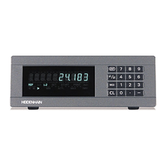
- Page 2 Display of actual value and input Numeric keypad (9 decades with algebraic sign) with decimal point SET START PRINT inch < > ACTL DIFF – HEIDENHAIN Status display with indicators...
- Page 3 Function Indicator Meaning • Set datum If the decimal point is also blinking: • Transfer input value Display is waiting for reference mark • Set display to value from P79 (P80!) traversing. If decimal point is not blinking: • Leave parameter list Reference mark has been traversed—display stores datum points in nonvolatile memory •...
- Page 4 3 m (9.9 ft) User's Manual ND 281B Adhesive plug-in feet For stacking ND 281B units This manual is for the ND 281 B measured value display with the following software number or higher: 349 797-04 The software number is indicated on a label on the...
-
Page 5: Table Of Contents
Contents Working with the ND Display Units Installation and Specifications Encoders Rear Panel, Accessories Reference Marks Mounting Switch-On, Traversing the Reference Marks Power Connection Datum Setting Linear/Angular Measuring Modes Finding Minimum and Maximum Values Operating Parameters List of Operating Parameters Sorting and Tolerance Checking Linear Encoders Measured Value Output... -
Page 6: Encoders
The ND 281 B display unit is designed for use with photo- electrical linear or angular encoders with sinusoidal signals: primarily for HEIDENHAIN MT length gauges. When shipped by HEIDENHAIN, the display units are set to the linear measurement mode. You can switch between the linear and angular modes by entering the code number 41 52 63 (see “Linear/Angular... -
Page 7: Reference Marks
Reference Marks The MT length gauges have one reference mark. The scales of other photoelectric linear or angular encoders can contain one reference mark or many distance-coded reference marks. If there is an interruption of power, the relationship between the Scale in Distance-coded linear encoder... -
Page 8: Switch-On, Traversing The Reference Marks
REF mode Switch-On, Traversing the Reference Marks ä Crossing over the reference marks automatically switches the Turn on the power. display to REF mode: The last assignment of display values to (Switch located on rear panel.) length gauge positions is stored in nonvolatile memory. •... -
Page 9: Datum Setting
Datum Setting The datum setting procedure assigns a display value to a known position. With the ND 200 series, you can set two separate datum points. There are several ways to set the datum: • Enter a numerical value, or •... -
Page 10: Finding Minimum And Maximum Values 1)
Finding Minimum and Maximum Values from a Series of Measurements After a series of measurements has been started, the display transfers the first measured value to the memory for minimum and maximum values. Every 0.55 ms, the display compares the current measured value with the memory contents: A new value is stored if it is greater than the stored maximum value or ACTL... - Page 11 Starting a series of measurements Switching between MIN, MAX, DIFF and ACTL displays Repeatedly It is not possible to switch between the displays as Select the display for a series of meas- described below if the switching input for external urements.
- Page 12 Starting a new series of measurements Repeatedly Select the indicator START. The START indicator starts blinking. START Start a new series of measurements. Ending a series of measurements Repeatedly Select the active indicator (MIN, ACTL, MAX, DIFF). The indicator that lit up last starts blinking. End the series of measurements.
-
Page 13: Sorting And Tolerance Checking
Sorting and Tolerance Checking In the sorting and tolerance checking mode, the display unit compares the displayed value with the programmed upper and lower sorting limits. The sorting and tolerance checking mode is enabled and disabled with operating parameter P17. Part 1 Entering sorting limits Sorting limits are entered in operating parameters P18 and P19... -
Page 14: Measured Value Output
Measured values can be transmitted over the RS-232-C/V.24 < > ACTL DIFF – HEIDENHAIN interface (X31), for example to a printer or PC. There are several ways to start measured value output: ä In the linear measurement mode: Press MOD repeatedly until the PRINT indicator starts blinking, then start measured value output with ENT. -
Page 15: Display Freeze
Display Freeze With the latch command, the display can be stopped for any period of time. The internal counter remains active. Parameter P23 selects the “display freeze” mode and offers three settings: Concurrent display, no display freeze—the display value • is the current measured value. -
Page 16: Error Messages
Error Messages Display Effect/Cause Display Effect/Cause Command for measured value Error during reception of param- RS232 FAST REC. ERROR output followed too quickly by eter and compensation-value lists. another. Other Error displays Encoder signal is too weak. SIGNAL If “OVERFLOW” appears, the measured value is too large or The scale may be contaminated. -
Page 17: Rear Panel, Accessories
Rear Panel Ports X1, X2, X31 and X41 comply with the recommendations in EN 50 178 for separation from line power. Encoder input X1 HEIDENHAIN flange socket 9-pin Input signals 11 µA Maximum encoder cable length 30 m (98.5 ft) - Page 18 RS-232-C/V.24 data interface (X31) 25-pin D-sub connection (female) Switching inputs and outputs EXT (X41) 25-pin D-sub connection (male) Power switch Input X1 for one Ground HEIDENHAIN connection Accessories 11 µA encoder Input X2 for one Connecting elements HEIDENHAIN...
-
Page 19: Mounting
Mounting 172 ± 0.2 6.77 ± .008" You can fasten the ND 281 B from below by using M4 screws (see illustration at right). Hole positions for mounting the ND display unit ND 281 B display units are stackable. Adhesive plug-in feet (supplied with your unit) prevent the stacked units from being moved out of place. -
Page 20: Power Connection
Power Connection The rear panel of the ND 281 B contains a connecting jack for a power cord with Euro connector (power cord supplied with the delivery). Minimum cross section of the power cord: 0.75 mm Power supply: 100 Vac to 240 Vac (–15% to +10%) Power supply: 50 Hz to 60 Hz (±... -
Page 21: Linear/Angular Measuring Modes
Linear/Angular Measuring Modes You can select the linear measuring mode or angular measuring mode by entering the code number 41 52 63: ➤ Select the user parameter P00 CODE (see "Operating Parameters"). ➤ Enter the code number 41 52 63. ➤... -
Page 22: Operating Parameters
To access a user parameter ... Operating Parameters ... after switching on the display: Operating parameters allow you to modify the operating characteristics of your ND display unit and define the While ENT ... CL is evaluation of the encoder signals. Display first user parameter. - Page 23 Code number for changing protected operating Functions for changing the operating parameters parameters Function Page forward If you wish to change protected operating parameters, you in the list of operating parameters must first enter the code number 9 51 48: ä...
-
Page 24: List Of Operating Parameters
List of Operating Parameters Parameter Settings / Function Parameter Settings / Function Enter a code number: Angle display P00 CODE P09 ANGLE 9 51 48: To change the protected +/- 180° +/- 180 DEG. ¥ operating parameters ENDLESS 41 52 63: To select the linear or angular 360°... - Page 25 Parameter Settings/ Function Parameter Settings/ Function Display stop for measured value output Counting mode P23 DISPL. P37 STEP Concurrent display, no display freeze; 0-1-2-3-4-5-6-7-8-9 COUNT 0-1 the display value is the current actual 0-2-4-6-8 COUNT 0-2 value DISPL. ACTL. COUNT 0-5 Frozen display;...
- Page 26 500 SP Displayed measuring length ..... L = 620.000 mm Distance-coded with 1000 • SP Actual length (measured, e.g. (e.g. for HEIDENHAIN LS ...C) 1000 SP with the VM 101 comparator Distance-coded with 2000 • SP system from HEIDENHAIN) ....L = 619.877 mm...
- Page 27 Parameter Settings / Function Parameter Settings / Function Additional blank lines In the linear measurement mode P51 RS232 P86 MOD during data output First indicator after pressing MOD BK LINE 1 £ £ÿ START PRINT Default setting: 1 ACTL DIFF Trigger limit 1 In the angular measurement mode P62 A1...
-
Page 28: Linear Encoders
Linear Encoders The ND 281 B display unit is designed for use together with photoelectrical encoders with sinusoidal signals—11 µA Display step with linear encoders You can select a specific display step by adapting the following operating parameters: • Signal period (P31) •... - Page 29 Recommended parameter settings for HEIDENHAIN linear encoders with 11 µA signals Model Reference Millimeters Inches marks Display Display step step in mm in inches P 31 P 43 P 33 P 38 P 33 P 38 Single 0.0005 0.00002 MT xx01 0.0002...
- Page 30 Recommd. parameter settings for HEIDENHAIN linear encoders with 11 µA signals (continued) Model Reference Millimeters Inches marks Display Display step step in mm in inches P 31 P 43 P 33 P 38 P 33 P 38 LS 106/106C Single/1000 0.001...
- Page 31 Recommended parameter settings for HEIDENHAIN linear encoders with 1 V signals Model Reference Millimeters Inches marks Display Display step step in mm in inches P 31 P 43 P 33 P 38 P 33 P 38 LIP 382 0.128 0.000002 0.0000001...
- Page 32 Recommended parameter settings for HEIDENHAIN linear encoders with 1 V signals (continued) Model Reference Millimeters Inches marks Display Display step step in mm in inches P 31 P 43 P 33 P 38 P 33 P 38 LB 382/382C Single/2000 0.005...
-
Page 33: Angle Encoders
Recommended parameter settings for HEIDENHAIN angle encoders with 11 µA / 1 V signals Model Reference Display marks step ROD 450 3600 Single 0.01° ROD 456 / ROD 486 0.005° / ROD 1080 0.001° 9000 ROD 250 C / ROD 280 C Dist.-... -
Page 34: Multipoint Axis Error Compensation
Such deviations are usually measured with a comparator measuring system (such • Spacing of the compensation points as the HEIDENHAIN VM 101). The spacing of the compensation points is expressed as: In the linear measurement mode: Spacing = 2 [µm]. - Page 35 Table for determining the point spacing Exponent Point spacing in mm in inches 0.064 0.0023“ 0.128 0.0050“ 0.256 0.0100“ 0.512 0.0200“ 1.024 0.0403“ 2.048 0.0806“ 4.016 0.1581“ 8.192 0.3225“ 16.384 0.6450“ 32.768 1.290“ 65.536 2.580“ 131.072 5.160“ 262.144 10.32“ 524.288 20.64“...
- Page 36 Selecting the compensation table, entering an axis correction Select the operating parameters. together COMP. NR. 01 with Enter the associated compensation value, e.g. 0.01 mm. Press MOD twice to Select P00 CODE. select COMP. NR. 02. (You cannot enter any values in the POS. NR. 02 box). P00 CODE COMP.
- Page 37 Deleting a compensation value table Select the operating parameters. together with Select P00 CODE. P00 CODE Enter the code number 10 52 96, confirm with ENT. DATUM Select the “delete” function. DELETE Confirm with ENT or cancel with CL. Exit the compensation table mode.
-
Page 38: Switching Inputs And Outputs Ext (X41)
Inputs at D-sub connection EXT (X41) Switching Inputs and Outputs EXT (X41) Function Danger to internal components! Voltage sources for external circuitry must conform 1, 10 to the recommendations in EN 50 178 for low- Reset display to zero, clear error message voltage electrical separation. - Page 39 Inputs Outputs Input signals Output signals Internal pull-up resistor 1 k , active with low level "Open collector" outputs, active with low level £ Trigger by making contact against 0 V or Delay until signal output: t 30 ms ³ by low-level signal over TTL logic device Signal duration of zero signal, trigger limit A1, A2: t 180 ms...
- Page 40 Setting and zero resetting the display With an external signal, you can set the display to the value selected in parameter P79 (pin 3) or reset each axis to zero (pin 2). Enabling and disabling REF mode Operating parameter P85 allows you to activate the input (pin 25) which will be used for setting the display externally to REF mode when the unit is switched on or when the power is restored after an interruption.
- Page 41 Switching signals Output As soon as the trigger points defined in parameters are reached, the corresponding outputs (pins 15, 16) are activated. You can set up to two trigger points. The switching point “zero” has a separate output (see “Zero crossover”). Path Switching point Signals for sorting and tolerance checking...
- Page 42 Switching signal for errors The display unit permanently monitors functions such as measuring signal, input frequency, and data output, and displays an error message if it detects an error. If errors occur that seriously influence measurement or data ERROR xx Error output, the display unit activates a switching output.
-
Page 43: Locking The Keypad
Locking the Keypad You can lock or release the keypad by entering the code number 24 65 84: ➤ Select the user parameter P00 CODE (see “Operating Parameters”). ➤ Enter the code number 24 65 84. ➤ Confirm the entry with ENT. ➤... -
Page 44: Displaying The Software Version
Displaying the Software Version To display the software version of the display unit, enter the code number 66 55 44: ➤ Select the user parameter P00 CODE. ➤ Enter the code number 66 55 44. ➤ Confirm your entry with ENT. ➤... -
Page 45: Distance-To-Go Mode
Function of switching outputs A1 and A2 Distance-to-Go Mode In the distance-to-go mode, switching outputs A1 (pin 15) and Normally, the display shows the actual position of the en- A2 (pin 16) have a different function: they are symmetrical to coder. -
Page 46: Rs-232-C/V.24 Data Interface (X31)
(below right). A cable with full SIGNAL SIGNAL wiring is available from HEIDENHAIN (Id. Nr. 274 545-...). On this type of cable, pin 6 and pin 8 are additionally connected over a jumper. Maximum cable length: 20 m (66 ft) - Page 47 Data format and control characters Pin layout RS-232-C/V.24 (X31) Data format 1 start bit Signal Assignment 7 data bits CHASSIS GND Chassis ground Even parity bit 2 stop bits Transmitted data Control characters Call measured value: STX (Ctrl B) Received data Interrupt DC3 (Ctrl S) Request to send Continue DC1 (Ctrl Q)
- Page 48 Operating parameters for measured value output Measured value output via PRINT function In the linear measurement mode, press MOD repeatedly Parameter Function until the PRINT indicator starts blinking. Baud rate Start the measured value output with ENT. P50 RS232 In the angular measurement mode, press MOD (this feature Number of additional blank lines for P51 RS232 can be disabled with operating parameter 86).
- Page 49 Measured value output after signal through the “Contact” EXT(X41) or “Pulse” inputs Pin 23 To start measured value output through the EXT interface (X41), you can either: ä Pin 1(0V) Close the “Contact” input (pin 23 on X41) against 0 V, for example with a simple switch (make contact);...
- Page 50 Measured value output with CTRL B L%=18 If the display unit receives the control character STX (Ctrl B) over the RS-232-C/V.24 interface, it transmits the current PRINT "V.24/RS-232-C" measured value back over the interface. Ctrl B is received OPEN "COM1:9600,E,7" AS#1 over the RXD line of the interface and the measured values PRINT #1, CHR$ (2);...
-
Page 51: Input/Output Of Parameter And
Input/Output of Parameter and Compensation-Value Lists REC. PARAM. The display unit is ready to receive a Calling the "data transfer" function: reqd. parameter list over the RS-232-C/V.24 interface. After successful reception of the together Select the operating parameters. parameter list, the display unit resets itself with and restarts. -
Page 52: Compensation-Value Lists
Note on the input/output of parameter and If the display unit receives invalid parameter values, it sets the compensation-value lists respective operating parameter to the default setting. Example: “P01 INCH = INCH = 3” With a terminal program (e.g. HyperTerminal, included with The value 3 is not allowed. -
Page 53: Output Format Of The Parameter List
Output Format of the Parameter List 1st line Each parameter output begins with the start character < * > ( HEX: 0x2A) <CR> <LF> 3 characters 2nd line Output of the counter designation N D - 2 8 1 <CR> <LF> 13 characters 5 characters 2 characters... - Page 54 b: Parameters: Parameter settings can be changed by entering a value (e.g.: LINEAR COMP. 13.600 etc.) C L A S 1 2 0 0 0 0 0 <CR> <LF> 15 characters 3 char. 13 characters 2 characters C O M P 1 4 0 0 .
- Page 55 Parameter list for ND 281 B: "Linear measurement" mode of operation (factory default setting) Parameter list Description Start character (*); ND-281 B Model of display unit; MM or IN; MM = MM = Unit of measure: MM = 0; INCH = 1; X1/X2 = X1 11 uAPP = Encoder input: X1 11µAPP = 0;...
- Page 56 Parameter list for ND 281 B: "Angular measurement" mode of operation (factory default setting) Parameter list Description Start character (*); ND-281 B Model of display unit; DEC (decimal) or DMS (min-sec); X1/X2 = X1 11 uAPP = Encoder input: X1 11µAPP = 0; X2 1VPP = 1; DISPL.
-
Page 57: Output Format Of The Compensation-Value Table
Output Format of the Compensation-Value Table Line: Start Each compensation-value output begins with the start character < * > ( HEX: 0x2A) <CR> <LF> 3 characters Line: Counter model designation Output of model designation and unit of measure N D - 2 8 1 <CR>... - Page 58 Compensation-value table for ND 281 B (linear measurement): factory default setting Compensation-value table Description: Start character ( * ); ND-281 B Model of display unit; unit of measure (MM or IN); SCALING Spacing = 14 ( range: 6 – 20) DATUM 0.0000 Datum point 0 mm (value input)
- Page 59 Compensation-value table for ND 281 B (angular measurement): Active compensation Compensation-value table Description: Start character ( * ); ND-281 B Model of display unit; DEC (decimal) or DMS (deg-min-sec); CMP. NR. 00 0.00.00 Compensation value 0 = 0.0000mm (compensation value 0 is always 0) CMP.
-
Page 60: Remote Operation Over The Rs-232-C/V.24
Sequence of commands Meaning Remote Operation over the RS-232-C/V.24 <ESC>T1000<CR> ‘CE+0‘ keys Data Interface <ESC>T1001<CR> ‘CE+1‘ keys <ESC>T1002<CR> ‘CE+2‘ keys You can operate the display unit remotely over the RS-232-C/ <ESC>T1003<CR> ‘CE+3‘ keys V.24 data interface. The following commands are available on <ESC>T1004<CR>... - Page 61 Description of RS-232-C/V.24 commands: Output of 14-segment display: The contents displayed are transmitted (also dialogs and error The display unit supports the XON-XOFF protocol when messages). executing commands. As soon as the internal character buffer (100 characters) is full, the display unit sends the control <STX>...
- Page 62 Output of software number: REF function: The current software number is transmitted. Activate or deactivate REF mode (current REF condition is changed). <STX> 3 4 9 7 9 7 - 0 4 <CR> <LF> String: STX; Print 10 characters; CR; LF; Output of the current measured value.
-
Page 63: Specifications
Specifications Housing ND 281 B Noise immunity As per VDE 0843 Parts 2 and 4, severity 4 Benchtop design, cast-metal housing (W · H · D) Protection IP40 according to IEC 529 239 mm · 84.6 mm · 224 mm Encoder inputs For linear and angle encoders with Operating temperature... - Page 64 ND 281 B: Dimensions in mm/inches REF 1 SET START PRINT inch < = > MIN ACTL MAX DIFF 172 ± 0.2 33.5 6.77" ± .008" 1.37" 9.41"...
- Page 65 HEIDENHAIN (G.B.) Limited 200 London Road, Burgess Hill West Sussex RH15 9RD, Great Britain { (014 44) 24 77 11 | (014 44) 87 00 24 350 267-22 · SW 349 797-04 · 6 · 12/2001 · E · Printed in Germany · Subject to change without notice...
Need help?
Do you have a question about the ND 281B and is the answer not in the manual?
Questions and answers