Table of Contents
Advertisement
Advertisement
Chapters
Table of Contents

Subscribe to Our Youtube Channel
Related Manuals for HEIDENHAIN ND 730


Summary of Contents for HEIDENHAIN ND 730
- Page 1 User’s Manual Position Display Units for Lathes 9/ 2000...
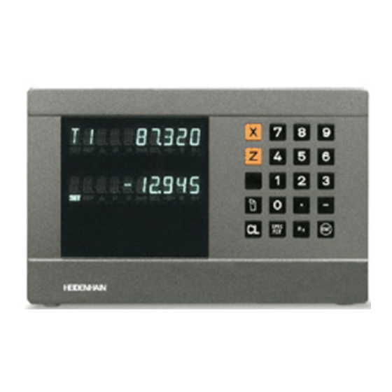
- Page 2 Position display • Select coordinate axes (ND 730 only two axes) (ND 730 only X and Z) • Select axis-specific operating parameters Status display: Numerical input SET = Set datum REF = Blinking: • Change algebraic sign Traverse reference • Call last dialog...
-
Page 3: Table Of Contents
Part I Operating Instructions This manual is for ND display units with the following software numbers or higher: Fundamentals ND 730 for two axes 246 271-06 ND 770 for three axes 246 271-06 Switch-On, Reference-Mark Traverse Selecting Radius or Diameter Display... -
Page 4: Fundamentals
Fundamentals You can skip this chapter if you are already familiar with Graduation coordinate systems, incremental and absolute dimensions, nominal positions, actual positions and distance-to-go! Coordinate system –X To describe the geometry of a workpiece, a rectangular or Cartesian* Datum or origin coordinate system is used. - Page 5 Cross slide, saddle and top slide On conventional lathes, the tool is mounted on a slide that moves in the direction of the X axis (the cross slide) and in the direction of the Z axis (the saddle). Most lathes have a top slide above the saddle. The top slide moves in Z axis direction and is designated Zo.
- Page 6 Datum setting The workpiece drawing is used as the basis for machining the workpiece. To enable the dimensions in the drawing to be converted into traverse distances of machine axes X and Z, each drawing dimension requires a datum or reference point on the workpiece Absolute datum (since a position can only be defined in relationship to another...
- Page 7 Tool datums (tool compensation) Your display unit should show you the absolute position of the workpiece, regardless of the length and shape of the particular tool being used. For this reason you must determine the tool data and enter it. First touch the workpiece with the cutting edge of the tool and then enter the associated display value for that position.
- Page 8 Absolute workpiece positions Each position on the workpiece is uniquely defined by its absolute coordinates. Example Absolute coordinates of position 5 mm Z = –35 mm If you are working according to a workpiece drawing with absolute dimensions, you are moving the tool to the coordinates. Relative workpiece positions A position can also be defined relative to the previous nominal position.
- Page 9 Position encoders The position encoders on the machine convert the movements of the machine axes into electrical signals. The ND display unit evaluates these signals, determines the actual position of the machine axes and displays the position as a numerical value. If the power is interrupted, the relationship between the machine axis Workpiece positions and the calculated actual positions is lost.
-
Page 10: Switch-On, Reference-Mark Traverse
Switch-On, Reference-Mark Traverse Turn on the power (switch located on rear panel). REF starts blinking in the status display. Confirm reference-point traverse. REF is now lighting. Decimal points are blinking. Cross over the reference marks in all axes (in any sequence). -
Page 11: Selecting Radius Or Diameter Display
Selecting Radius or Diameter Display Your ND can display positions in the cross slide as a diameter or as a radius. Drawings of lathe parts usually indicate diameters. When you are turning the part, however, you infeed the tool in the cross slide axis in radius values. -
Page 12: Separate Value/Sum Display
Separate Value/Sum Display (ND 970 only) Separate value display In this mode the positions of the saddle and top slide are displayed separately. The position displays are referenced to the datum points that you set for the Zo and Z axes. When an axis slide moves, only the 0 +10 position display for that axis changes. -
Page 13: Datum Setting
X axis depends on whether you have selected radius or diameter display. With the ND 730/ND 770 position displays, you can set one absolute workpiece datum and data for up to 9 tools (relative datums). Setting the absolute workpiece datum When you enter a new value for the absolute workpiece datum, all tool data are then based on the new workpiece datum. -
Page 14: Entering Tool Data (Relative Datums)
Entering tool data (relative datums) Touch the workpiece or turn the first Select tool, T begins to blink. diameter. Enter tool number, e.g. 3, and confirm with ENT. Select the axis (for example X), enter the position of the tool tip (for example 20 mm), and confirm with ENT. -
Page 15: Holding Positions
Holding Positions If you want to measure the workpiece after turning the first diameter, your display unit has to capability to “freeze” (hold) the actual position before you retract the tool. Turn the first diameter, for example in the X axis. Select Special Functions. - Page 16 Enter the measured position, for example 12 mm, e.g. and confirm with ENT. The display shows the current tool position. SPEC End the function.
- Page 17 Moving the Axes with the Distance-To-Go Display Normally, the display shows the actual position of the tool. However, it is often more helpful to display the remaining distance to the nominal position (distance-to-go). You can then position simply by moving the axis until the display value is zero.
- Page 18 Select the axis, e.g. Z, enter the nominal coordinate, e.g. –20 mm, and confirm with ENT. Move the Z axis until the display value is zero. The tool is at position 2. Select the axis, enter the nominal coordinate, e.g. 20 mm (radius), confirm with ENT. Move the X axis until the display value is zero.
-
Page 19: Taper Calculator
Taper Calculator The taper calculator enables you to calculate the angle for the top slide. There are two possibilities: • Calculation from the taper ratio: - Difference between the taper radii to the length of the taper • Calculation from two diameters and the length: - Starting diameter - Final diameter - Length of the taper... - Page 20 TAP. RATIO Confirm function. 1. VALUE Enter the first value, e.g. 1, and confirm with ENT 2. VALUE Enter the second value, e.g. 3, confirm with ENT (length of taper is three times as large as radius difference). ANGLE = 18.435 The result is displayed in the message field.
- Page 21 Calculation from two diameters and the length Select Special Functions. SPEC Select Taper Calculator for input of diameters and SPEC length. TAPER CALC. Confirm function. TAP. RATIO Select Taper Dimensions function. TAP. DIMENS. Confirm function. • • •...
- Page 22 DIA. RIGHT Enter value, e.g. 10 mm, confirm with ENT. DIA. LEFT Enter value, e.g. 20 mm, confirm with ENT. LENGTH Enter value, e.g. 30 mm, confirm with ENT. ANGLE = 9.462 The result is displayed in the message field. End the taper calculator.
-
Page 23: Error Messages
Error Messages Message Cause and Effect The encoder signal is too weak. SIGNAL X The scale may be contaminated. The spacing of the reference ERR. REF. X marks as defined in P43 is not the same as the actual spacing. The input frequency for this FRQ. - Page 24 Entering/changing operating parameters Operating parameter list Linear Encoders Setting the display step Display step, signal period and subdivision Compatible HEIDENHAIN linear encoders Multipoint Axis Error Compensation Input in compensation value table Selecting compensation value table, entering axis error values Deleting compensation value table...
-
Page 25: Items Supplied
Items Supplied • ND 730 for 2 axes • ND 770 for 3 axes • Power connector Id. Nr. 257 811-01 • User's Manual Optional Accessories • Tilting base for mounting on underside of housing Id. Nr. 281 619-01... -
Page 26: Connections On Rear Panel
Connections on Rear Panel ID label Power switch Power input Ground terminal Encoder inputs X1 to X3 Rubber feet with M4 thread Connections X1, X2, X3 meet the regulations for safe separation from line power according to EN 50 178! -
Page 27: Mounting
Mounting To mount the display unit on a support, use the M4 threaded holes in the rubber feet. You can also mount the display unit on the optional tilting base. Tilting base Support Power Connection Hot leads Protective ground • Danger of electrical shock! Connect a protective ground. -
Page 28: Connecting The Encoders
Connecting the Encoders Your display unit will accept all HEIDENHAIN linear encoders with sinusoidal output signals (11 to 16 µA ) and distance-coded or single reference marks. Assignment of the encoder inputs for the ND 730 Encoder input X1 is for the X axis... -
Page 29: Operating Parameters
Some operating parameters have separate values for each axis. Such parameters have an additional index number from Changing parameter settings 1 to 3 with the ND 770 and from 1 to 2 with the ND 730. Press the minus key or enter the value and confirm Example: P12.1 scaling factor, X axis... - Page 30 List of operating parameters P00 CODE Enter the code number P30.1 to P30.3 Counting direction 9 51 48: Change protected operating parameters Positive counting direction with 66 55 44: Display the software version (in the X axis) positive direction of traverse DIRECT.
- Page 31 Example: Displayed length L a = 620.000 mm Actual length (as determined for example with P48.1 to P48.3 Activate axis display the VM 101 from HEIDENHAIN) Axis display active AXIS ON L a = 619.876 mm Difference ∆L = L a – L d = –124 µm...
-
Page 32: Linear Encoders
Linear Encoders Setting the display step with linear encoders The display step depends on the: • Signal period (P31) • Counting step (P33) • Decimal places (P38) Example Linear encoder with signal period 10 µm Required display step ....0.000 5 mm Signal period (P31) .... - Page 33 Parameter settings for HEIDENHAIN linear encoders with 11 µA signals Model Reference Millimeters Inches marks Display step Display [mm] step [inch] P 31 P 43 P 33 P 38 P 33 P 38 single 0.0005 0.00002 MT xx01 0.0002 0.00001 0.0001...
- Page 34 Param eter settings for HEIDENHAIN linear encoders 11 µA (continued) M odel Reference M illim eters Inches m arks Display step Display [m m ] step [inch] P 31 P 43 P 33 P 38 P 33 P 38 LS 106/106C single/1000 0.001...
-
Page 35: Multipoint Axis Error Compensation
Multipoint Axis Error Compensation Entries in the compensation value table • Axis to be compensated: X, Zo or Z If you want to use the multipoint axis error compen- (Zo only ND770) sation feature, you must • Axis with error: X, Zo or Z •... - Page 36 To select comp. value table and enter an axis correction DATUM X Select Special Functions SPEC Enter the active datum for the error on the axis to be corrected e.g. 27 mm, and confirm. Select the Parameter function if required, SPEC by repeatedly pressing the TOOL key.
-
Page 37: Selecting Compensation Value Table
Deleting a compensation value table Select Special Functions. SPEC Select the Parameter function. SPEC P A R A M E T E R Select the dialog for entering the code numebr. C O D E Enter105296 and confirm with ENT. 1 0 5 2 AXIS X Select the compensation value table,... -
Page 38: Specifications
Specifications Housing ND 730/ND 770 Encoder inputs For encoders with Bench-top design, cast metal 7 to 16 µA Dimensions (W • H • D) Grating period 2, 4, 10, 20, 40, 100, 270 mm x 172 mm x 93 mm 200 µm and 12.8 mm... - Page 39 Dimensions in mm/inches Tilting base 38 ± 0.5 1.5 ± .02" 3.622" 210 ± 0.2 .6" 8.268 ± .008" 9.45"...
- Page 40 HEIDENHAIN (G.B.) Limited 200 London Road, Burgess Hill West Sussex RH15 9RD, Great Britain { (0 14 44) 24 77 11 | (0 14 44) 87 00 24 341 697-22 · SW246 271-06 · 15 · 9/2000 · F&W · Printed in Germany · Subject to change without notice...
Need help?
Do you have a question about the ND 730 and is the answer not in the manual?
Questions and answers