Table of Contents
Advertisement
Advertisement
Chapters
Table of Contents

Related Manuals for HEIDENHAIN ND 710


Summary of Contents for HEIDENHAIN ND 710
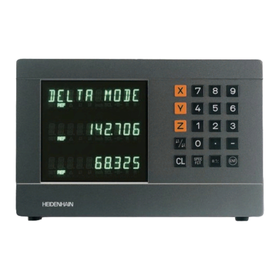
- Page 1 User’s Manual Position Display Units for Milling Machines 6/99...
- Page 2 Position display • Select coordinate axes (ND 710 only two axes) (ND 710 only X and Y) • Select axis-specific operating parameters Numerical input Status display: SET = Datum setting REF = blinking: • Change the algebraic sign Traverse the •...
-
Page 3: Table Of Contents
Part I Operating Instructions This manual is for the ND display units with the following software numbers or higher: ND 710 for two axes AA00 Fundamentals ND 750 for three axes AA00 Switch-On, Traversing the Reference Points Datum Setting Tool Compensation... -
Page 4: Fundamentals
Fundamentals You can skip this chapter if you are already familiar with Graduation coordinate systems, incremental and absolute dimensions, nominal positions, actual positions and distance-to-go. Coordinate system To describe the geometry of a workpiece, the Cartesian* coordinate –X Datum or system is used. - Page 5 Datum setting The workpiece drawing is used as the basis for machining the workpiece. To enable the dimensions in the drawing to be converted into traverse distances of machine axes X, Y and Z, each drawing dimension requires a datum or reference point on the workpiece 216,5 (since a position can only be defined in relationship to another position).
- Page 6 Absolute workpiece positions Each position on the workpiece is uniquely defined by its absolute coordinates. Absolute coordinates of position 1: Example 10 mm 5 mm 0 mm If you are working according to a workpiece drawing with absolute dimensions, then you are moving the tool to the coordinates. Relative workpiece positions A position can also be defined relative to the previous nominal position.
- Page 7 Nominal position, actual position and distance-to-go The position to which the tool is to move is called the nominal position ( ). The position at which the tool is actually located at any given moment is called the actual position ( The distance from the nominal position to the actual position is called the distance-to-go ( Sign for distance-to-go...
- Page 8 Position encoders The position encoders on the machine convert the movements of the machine axes into electrical signals. The ND display unit evaluates these signals, determines the actual position of the machine axes and Workpiece displays the position as a numerical value. If the power is interrupted, the relationship between the machine axis positions and the calculated actual positions is lost.
- Page 9 Switch-On, Traversing the Reference Marks Turn on power (switch located on rear panel). REF and decimal points in status display blink. ENT...CL Confirm reference traverse mode. REF remains on continuously. Decimal points blink. Cross over the reference marks in all axes (in any sequence).
-
Page 10: Datum Setting
Datum Setting Datum setting with the tool Example: If you want to save the datum points in nonvolatile memory, you must first cross over the reference marks. Working plane X / Y Only after crossing over the reference marks can you set new datums Tool axis or activate existing ones. - Page 11 Select the datum number. X position is captured. SET blinks. Retract tool from workpiece. Status display <- lights up. Select special functions. SPEC Enter position value for the datum. • Tool radius is automatically Select “probing function.” SPEC • compensated. •...
- Page 12 Select the Z axis. SET lights up. Status display <- blinks. PROBE Z (appears only briefly) Touch the top of the workpiece with the tool. Z position is captured. SET blinks. Retract the tool from the workpiece. Status display <- lights up. Enter the position value for the datum in the Z axis.
-
Page 13: Tool Compensation
Tool Compensation TOOL AXIS You can enter the axis, length and diameter of the current tool. Set the tool axis. Select the special functions. SPEC TOOL AXIS Exit the special functions. SPEC Select “tool diameter.” SPEC TOOL DATA Confirm tool data input mode. TOOL DIAM. -
Page 14: Moving The Axes With Distance-To-Go
Moving the Axes with Distance-To-Go Display Normally, the display shows the actual position of the tool. However, it is often more helpful to display the distance remaining to the nominal position (the distance-to-go). You can then position simply by moving the axis until the display value is zero. - Page 15 Move the machine axis to zero 1. Select the axis, enter the nominal value, e.g. 30 mm, select radius compensation R–, and confirm with ENT. Move the machine axis to zero 2. Select the axis, enter the nominal value, e.g. 50 mm, select radius compensation R+, confirm with ENT.
-
Page 16: Bolt Hole Circles And Bolt Circle Segments
Bolt Hole Circles and Bolt Circle Segments Your display unit enables you to quickly and easily drill bolt hole circles and bolt hole circle segments. The required data is requested in the message field. Each hole can be moved to by traversing to display value zero. This requires entry of the following data: •... - Page 17 Select the special functions. SPEC CENTER X Enter the X coordinate of circle center, e.g. 50 mm, confirm with ENT. Select “bolt hole” circle. SPEC BOLT HOLE CENTER Y Confirm your selection. Enter the Y coordinate of circle center, e.g. 50 mm, confirm with ENT. FULL CIRCLE Confirm “full circle.”...
- Page 18 HOLE DEPTH Enter the total hole depth, e.g. –5 mm, and confirm with ENT. START Start the display of the hole positions. After the start, the distance-to-go mode becomes active (∆ symbol lights up). The hole number is shown briefly in the X axis. The individual holes are reached by traversing to zero.
-
Page 19: Linear Hole Patterns
Linear Hole Patterns The linear hole pattern feature allows you to easily create rows of holes to cover an area. The required data are requested in the message field. You can position to each hole by traversing to display value zero. The following data are required: •... - Page 20 Select special functions. SPEC HOLES ROW Enter the number of holes per row, Select “hole pattern.” e.g. 4, and confirm with ENT. SPEC LIN. HOLE HOLE SPACE Confirm “linear hole” pattern. Enter the spacing between holes in the row and confirm with ENT. 1ST HOLE X Enter the X coordinate of the first holes, e.g.
- Page 21 NUMBER ROW Enter the number of rows, e.g. 3, and confirm with ENT. ROW SPACE Enter the spacing of the rows, e.g. 20, and confirm with ENT. START Start the display of hole positions. The distance-to-go mode is now active (∆...
-
Page 22: Working With A Scaling Factor
Working with Scaling Factors Scaling factors enable you to increase or decrease the display values based on the actual traverse distance. The display values are changed symmetrically about the datum. Enter scaling factors separately for each axis in parameter P12. Parameter P11 activates and deactivates the scaling factors in all axes (see “Operating Parameters”). -
Page 23: Error Messages
Error messages To erase error messages: Message Cause and effect After you have removed the cause of error: Encoder signal is too small, Press the CL key. SIGNAL X e.g. when an encoder is contaminated. Before touching off on the PROB. - Page 24 Operating Parameters Entering/changing operating parameters Operating parameter list Linear Encoders Setting the display step Display step, signal period, and subdivision Parameter settings for HEIDENHAIN linear encoders with 11 µApp Multipoint Axis Error Compensation Specifications Dimensions of the ND 710/ND 750...
-
Page 25: Items Supplied
Items Supplied • ND 710 for 2 axes • ND 750 for 3 axes • Power connector Id. Nr. 257 811-01 • User's Manual Optional Accessories • Tilting base for housing bottom Id. Nr. 281 619-01... -
Page 26: Connections On Rear Panel
Connections on Rear Panel ID label Power switch Power input Protective ground Encoder inputs X1 to X3 Rubber feet with M4 thread The interfaces X1, X2, X3 comply with the requirements for electrical separation according to EN 50178! -
Page 27: Mounting
Mounting ND 710/ND 750 To mount the display unit on a support, use the M4 threaded holes in the rubber feet. You can also mount the display unit on the optional tilting base. Tilting base Support Power Connection Power leads: Connect protective ground to •... -
Page 28: Connecting The Encoders
Connecting the Encoders Your display unit will accept all HEIDENHAIN linear encoders with sinusoidal output signals (7 to 16 µA ) and distance-coded or single reference marks. Assignment of the encoder inputs Encoder input X1 is for the X axis... -
Page 29: Operating Parameters
To change parameter settings axis. In the ND 750, these parameters are identified by an index of 1 to 3, and in the ND 710 by an index of one to two. Press the minus key or enter the value and confirm Example: P12.1 scaling factor, X axis... - Page 30 List of operating parameters P32.1 to P32.3 Subdivision of the encoder signals P1 Unit of measure 1) 20 / 10 / 8 / 5 / 4 / 2 / 1 / 0.8 / 0.5 / 0.4 / 0.2 / 0.1 Display in millimeters Display in inches INCH...
- Page 31 P80 Function of the CL key Actual length (as determined for example with Reset to zero with CL CL...RESET the VM 101 from HEIDENHAIN) No reset to zero with CL CL..OFF L a = 619.876 mm Difference ∆L = L –...
-
Page 32: Linear Encoders
Linear Encoders Display step, signal period and subdivision for linear encoders Selecting the display step with linear encoders Signal period [µm] To select a certain display step you must define the Display step following operating parameters: [mm] [inch] P32: Subdivision •... - Page 33 Parameter settings for HEIDENHAIN linear encoders with 11 µA signals Model Reference Millimeters Inches marks Display Display step [mm] step [inch] P 43 P 32 P 33 P 38 P 32 P 33 P 38 single 0,0005 0,00002 MT xx01...
-
Page 34: Multipoint Axis Error Compensation
Spacing of the compensation points usually measured with a comparator measuring system (such The spacing of the compensation points is expressed as as the HEIDENHAIN VM 101). [µm]. For example, you can determine the screw pitch error X=F(X) Enter the value of the exponent x into the compensation for the X axis. - Page 35 Selecting the compensation table, entering an axis correction Select special functions. DATUM X SPEC Enter the active datum for the error on the axis to be corrected (e.g. 27 mm) and confirm with ENT. Select "parameter" if required, by SPEC repeatedly pressing the 1 2 key.
- Page 36 Deleting a compensation value table Select special functions. SPEC Select “parameter.” SPEC PARAMETER Select the dialog for entering the code number. CODE Enter the code number 105296 and 1 0 5 2 confirm with ENT. AXIS Select the compensation value table (e.g., for the Z axis), and delete the table.
-
Page 37: Specifications
Specifications Housing ND 710/ND 750 Encoder inputs For encoders with 7 to 16 µA Bench-top design, cast-metal housing Grating period 2, 4, 10, 20, 40, 100, and 200 µm Dimensions (W • H • D) 270 mm • 172 mm • 93 mm... - Page 38 Dimensions mm/inches Tilting base 38 ± 0.5 1.5 ± .02" 3.622" 210 ± 0.2 .6" 8.268 ± .008" 9.45"...
- Page 39 341 695-21 · SW AA00 · 15 · 6/99 · F&W · Printed in Germany · Subject to change without notice...
Need help?
Do you have a question about the ND 710 and is the answer not in the manual?
Questions and answers