
Related Manuals for HEIDENHAIN ND 720


Summary of Contents for HEIDENHAIN ND 720
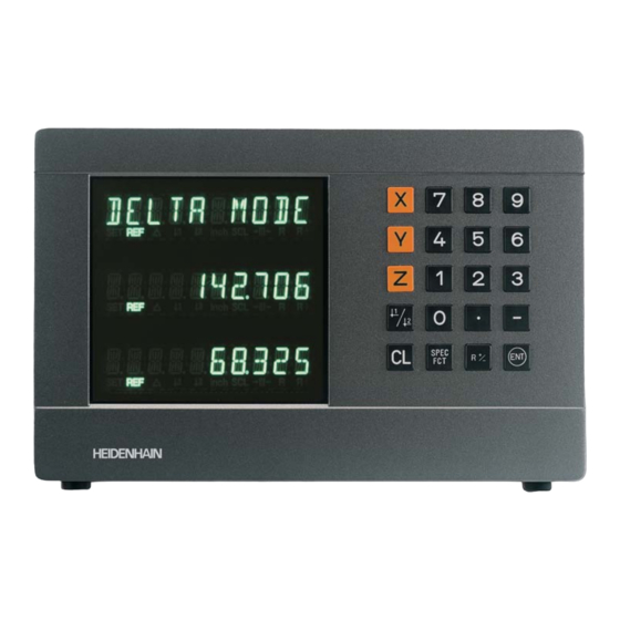
- Page 1 User’s Manual ND 720 ND 760 Position Display Units for Milling Machines English (en) 12/2001...
- Page 2 • Select coordinate axes Position display (ND 720 only X and Y) (ND 720 only two axes) • Select axis-specific operating parameters Numerical input Status display: SET = Datum setting REF = blinking: • Change the algebraic sign Traverse the reference points.
-
Page 3: Table Of Contents
Part I Operating Instructions This manual is for the ND display units with the following software numbers or higher: ND 720 for two axes 246 271-07 Fundamentals ND 760 for three axes 246 271-07 Switch-On, Traversing the Reference Marks Datum Setting... -
Page 4: Fundamentals
Fundamentals You can skip this chapter if you are already familiar with Graduation coordinate systems, incremental and absolute dimensions, nominal positions, actual positions and distance-to-go. Coordinate system The Cartesian coordinate system is used to describe the geometry of – X Datum or a workpiece. - Page 5 Datum setting The workpiece drawing is used as the basis for machining the workpiece. To enable the dimensions in the drawing to be converted into traverse distances of machine axes X, Y and Z, each drawing dimension requires a datum or reference point on the workpiece 216,5 (since a position can only be defined in relationship to another position).
- Page 6 Absolute workpiece positions Each position on the workpiece is uniquely defined by its absolute coordinates. Example Absolute coordinates of position 1: 10 mm 5 mm 0 mm If you are working according to a workpiece drawing with absolute dimensions, then you are moving the tool to the coordinates. Relative workpiece positions A position can also be defined relative to the previous nominal position.
- Page 7 Nominal position, actual position and distance-to-go The position to which the tool is to move is called the nominal position ( ). The position at which the tool is actually located at any given moment is called the actual position ( The distance from the nominal position to the actual position is called the distance-to-go ( Sign for distance-to-go...
- Page 8 Position encoders The position encoders on the machine convert the movements of the machine axes into electrical signals. The ND display unit evaluates these signals, determines the actual position of the machine axes and Workpiece displays the position as a numerical value. If the power is interrupted, the relationship between the machine axis positions and the calculated actual positions is lost.
-
Page 9: Switch-On, Traversing The Reference Marks
Switch-On, Traversing the Reference Marks Turn on power (switch located on rear panel). 0 è 1 “REF” in status display starts blinking. ENT...CL Confirm reference traverse mode. “REF” remains on continuously. Decimal points start blinking. Cross over the reference marks in all axes in any sequence. -
Page 10: Datum Setting
Datum Setting To call a datum you have set, proceed as follows: If you want to save the datum points in nonvolatile memory, you must first cross over the reference You have set two datum points in P70: marks. Select datum 1 or 2. Only after crossing over the reference marks can you set new datums or activate existing ones. -
Page 11: Datum Setting With The Tool
Datum setting with the tool Select a datum number (see page 10). Example: Working plane X / Y Select the special functions. SPEC Tool axis Tool radius R = 5 mm Select the probing function. Axis sequence X – Y – Z SPEC for datum setting PROBING... - Page 12 PROBE X (appears only briefly) Enter position value for the datum • in the Y axis. Tool radius is automatically • Touch workpiece edge 1 with the tool. compensated. • Select the Z axis. “SET” lights. The ❘<- status symbol starts blinking. X position is captured.
-
Page 13: Datum Setting With The Kt Edge Finder
Datum setting with the KT Edge Finder The ND position display units provide the following probing functions: “PROBE EDGE” Setting a workpiece edge as datum “PROBE MIDPOINT” Setting a midpoint between two workpiece edges as datum “PROBE CIRCLE” Setting the center of a circle as datum The probing functions are accessible in the SPEC FCT mode of operation. - Page 14 Probing a workpiece edge to find a datum The edge to be probed is parallel to the Y axis. You can probe edges and surfaces as described below to set all the coordinates of a datum. Select a datum number (see page 10). Select the special functions.
- Page 15 Select the X axis (if not already selected). “SET” lights. The ❘< status symbol starts blinking. PROBE X (appears only briefly) Move the edge finder to edge of workpiece until indicator in edge finder lights. “SET edge” is shown briefly. SET starts blinking. The ND displays the position of the edge.
- Page 16 Probing workpiece edges to find a midpoint datum The edges to be probed run parallel to the Y axis. Follow the procedure below for all midpoints between two edges. Select a datum number (see page 10). Select the special functions. SPEC Select the probing function.
- Page 17 Set the position value for the midpoint PROBE MIDP. between the edges, e.g. 26. Confirm the “probe midpoint” function. “SET” lights. Exit the probing functions. SPEC Select the X axis (if not already selected). The ->❘❘<- status symbol starts blinking. 1ST POS X (appears only briefly) Move edge finder toward workpiece edge 1 until the indicator in the edge...
- Page 18 Probing the inside of a circle to set its center as datum To determine the circle center, the tool must probe four points. The points to be probed are located in the X-Y plane. Select a datum number (see page 10). Select the special functions.
- Page 19 4TH POS Y (appears only briefly) PROBE CIRC. Move edge finder toward Confirm “Probe circle.” position 4 until the indicator in the edge finder lights. “CENTER X” is shown briefly. The SET status display starts to blink in the X axis. 1ST POS X (appears only briefly) Move edge finder toward position 1 until the indicator in the edge finder...
-
Page 20: Tool Compensation
Tool Compensation TOOL AXIS You can enter the axis, length and diameter of the current tool. Set the tool axis. Select the special functions. SPEC TOOL AXIS Exit the special functions. SPEC Select “tool data”. SPEC TOOL DATA Confirm tool data input mode. TOOL DIAM. -
Page 21: Moving The Axes With Distance-To-Go
Moving the Axes with Distance-To-Go Display Normally, the display shows the actual position of the tool. However, it is often more helpful to display the distance remaining to the nominal position (the distance-to-go). You can then position simply by moving the axis until the display value is zero. - Page 22 Move the machine axis to zero (1). Select the axis, enter the nominal value, e.g. 30 mm, select radius compensation R–, and confirm with ENT. Move the machine axis to zero (2). Select the axis, enter the nominal value, e.g. 70 mm, select radius compensation R+, confirm with ENT.
-
Page 23: Bolt Hole Circles And Bolt Hole Circle Segments
Bolt Hole Circles and Bolt Hole Circle Segments Your display unit enables you to quickly and easily produce bolt hole circles and bolt hole circle segments. The required data is requested in the message field. Each hole can be moved to by traversing to display value zero. This requires entry of the following data: •... - Page 24 Select the special functions. SPEC CENTER X Enter the X coordinate of circle center, e.g. 50 mm, confirm with ENT. Select “bolt hole” circle. SPEC BOLT HOLE CENTER Y Confirm your selection. Enter the Y coordinate of circle center, e.g. 50 mm, confirm with ENT. FULL CIRCLE Confirm “full circle.”...
- Page 25 HOLE DEPTH Enter the total hole depth, e.g. –5 mm, and confirm with ENT. START Start the display of the hole positions. After the start, the distance-to-go mode becomes active (the D symbol lights). The hole number is shown briefly in the X axis. The individual holes are reached by traversing to zero.
-
Page 26: Linear Hole Patterns
Linear Hole Patterns The linear hole pattern feature allows you to easily create rows of holes to cover an area. The required data are requested in the message field. You can position to each hole by traversing to display value zero. The following data are required: •... - Page 27 Select the special functions. SPEC HOLES ROW Enter the number of holes per row, Select “hole pattern”. e.g. 4, and confirm with ENT. SPEC LIN. HOLE HOLE SPACE Confirm “linear hole” pattern. Enter the spacing between holes in the row and confirm with ENT. 1ST HOLE X Enter the X coordinate of the first holes, e.g.
- Page 28 NUMBER ROW Enter the number of rows, e.g. 3, and confirm with ENT. ROW SPACE Enter the spacing of the rows, e.g. 20, and confirm with ENT. START Start the display of hole positions. The distance-to-go mode is now active (the D symbol lights).
-
Page 29: Working With A Scaling Factor
Working with a Scaling Factor Scaling factors enable you to increase or decrease the display values based on the actual traverse distance. The display values are changed symmetrically about the datum. Enter scaling factors separately for each axis in parameter P12. Parameter P11 activates and deactivates the scaling factors in all axes (see “Operating Parameters”). -
Page 30: Error Messages
Error Messages Message Cause and Effect Message Cause and Effect Checksum error: Check the Time interval between two commands ERR. MEMORY RS TOO FAST datum, operating parameters and too short. compensation values for Encoder signal is too weak, SIGNAL X multipoint axis error e.g. - Page 31 Multipoint Axis Error Compensation Pin Layout of X10 Data Interface RS-232-C/V.24 Measured-Value Output Input/Output of Parameter Lists and Compensation-Value Lists Output Structure of Parameter Lists Output Structure of Compensation-Value Tables External Operation via RS-232-C/V.24 Data Interface Specifications Dimensions of ND 720/ND 760...
-
Page 32: Items Supplied
Items Supplied • ND 720 for 2 axes • ND 760 for 3 axes • Power connector Id. Nr. 257 811-01 • User's Manual Optional accessories • Tilting base for housing bottom Id. Nr. 281 619-01 • KT 130 Edge Finder Id. Nr. 283 273-01... -
Page 33: Connections On Rear Panel
Connections on Rear Panel ID label Power switch Power input • Edge finder input • RS-232-C/V.24 data interface Protective ground Encoder inputs X1 to X3 Rubber feet with M4 thread The interfaces X1, X2, X3, and X10 comply with the requirements for electrical separation according to EN 50 178! -
Page 34: Mounting
Mounting ND 720/ND 760 To mount the display unit on a support, use the M4 threaded holes in the rubber feet. You can also mount the display unit on the optional tilting base. Tilting base Support Power Connection Power leads:... -
Page 35: Connecting The Encoders
Connecting the Encoders Your display unit will accept all HEIDENHAIN linear encoders with sinusoidal output signals (7 to 16 mA ) and distance-coded or single reference marks. Assignment of the encoder inputs Encoder input X1 is for the X axis... -
Page 36: Operating Parameters
➤ Page backwards by pressing the 1 2 key. 1 to 3 with the ND 760 and from 1 to 2 with the ND 720. Operating parameters with an index number can be selected To change parameter settings with the axis-direction keys. -
Page 37: Operating Parameter List
List of operating parameters P25 Stylus diameter Input range (mm): 0.000 to 999.999 Default setting: P00 CODE Enter code number 9 51 48: Change protected operating parameters P26 Stylus length 66 55 44: Display the software version (in the X axis) Input range (mm): 0.000 to 999.999 Display the date of release (in the Y axis) - Page 38 Example: Displayed length L d = 620.000 mm Amplitude and frequency Actual length (as determined for example with monitoring ALARM ON the VM 101 from HEIDENHAIN) No monitoring ALARM OFF L a = 619.876 mm Difference DL = L – L = –...
- Page 39 P50 Baud rate P97 Characters for measured values 110 / 150 / 300 / 600 / 1200 / 2 400 / 4 800 / 9600 / ASCII characters for designation of the measured values for 19 200 / 38 400 output through probing, contact, or pulse.
-
Page 40: Linear Encoders
Linear Encoders Selecting the display step with linear encoders To select a certain display step, you must define the following operating parameters: • Signal period (P31) • Counting mode (P33) • Decimal places (P38) Example Linear encoder with a signal period of 20 µm Desired display step .... -
Page 41: Compatible Heidenhain Linear Encoders
Parameter settings for HEIDENHAIN linear encoders with 11 µA signals Model Reference Millimeters Inches marks Display step Display [mm] step [inch] P 31 P 43 P 33 P 38 P 33 P 38 single 0.0005 0.00002 MT xx01 0.0002 0.00001 0.0001... - Page 42 Parameter settings for HEIDENHAIN linear encoders with 11 µA signals (continued) Model Reference Millimeters Inches marks Display step Display [mm] step [inch] P 31 P 43 P 33 P 38 P 33 P 38 LS 106/106C single/1000 0.001 0.00005 LS 406/406C 0.0005...
-
Page 43: Multipoint Axis Error Compensation
Such deviations are usually measured with a comparator measuring system (such • Spacing of the compensation points as the HEIDENHAIN VM 101). The spacing of the compensation points is expressed as You can, for example, determine the screw pitch error X=F(X) [µm]. - Page 44 Selecting the compensation table, entering an axis correction FCT. X Select the special functions. Enter the axis causing the error, e.g. X SPEC (screw pitch error), and confirm with ENT. Select the "parameter" function if required, by repeatedly pressing the SPEC DATUM X 1 2 key.
- Page 45 Deleting a compensation value table 28.024 Select the special functions. SPEC Enter all further compensation points. If you press the minus key, the unit will show the number of the current Select the “parameter" function. compensation point in the X display. SPEC Direct selection of compensation points: Press the minus key together...
-
Page 46: Pin Layout Of X10
Pin Layout of X10 for KT 130 Edge Finder and Data Interface Signal Function Internal shield Standby Receive data Request to send Clear to send +5 V SIGN. GND Signal ground Transmit data Data set ready Data terminal ready Meas. value output by contact Switching signals Meas. - Page 47 RS-232-C/V.24 Full wiring In addition to a connection for the edge finder, the X10 socket also provides an RS-232-C/V.24 data interface. The data interface on your ND display unit enables you to use a printer or CHASSIS CHASSIS a PC for transferring measured values or programs. The interface is permanently set to the following data format: 1 start bit SIGNAL...
-
Page 48: Measured-Value Output
Measured Value Output Measured values can be output over the RS-232-C/V.24 interface. This can be done with the following functions: Probing with the KT Edge Finder Contact input on X10 Pulse input on X10 CTRL B via the RS-232-C interface Code letters with the measured value Example of measured value output: Parameter P97 allows you to select a code letter to be output together... - Page 49 Measured value output when probing Parameter P96 allows you to activate measured value output when probing with the KT edge finder. The edge finder is connected to D-sub input X10. Whenever the Probe Edge function is used, your display unit outputs the position of the edge in the selected axis and the actual positions of the other axes over the TXD line of the RS-232-C/V.24 interface.
- Page 50 Examples of measured value output when probing ➀ Probed axis <PR>, <CL> / other axes ➁ Colon Example: Probe edge, X axis ➂ Plus or minus sign ➃ 1 to 8 places before the decimal point + 58541 . 2504 <CR>...
- Page 51 Measured value output over the contact and pulse inputs Measured value output over the contact input (pin 12 on X10) and pulse input (pin 14 on X10) can be triggered when these inputs are closed against 0 V. Pin 12 The measured values are output over the TXD line of the RS-232-C interface.
- Page 52 Measured value output with CTRL B BASIC program for measured value output: If the control character STX (CTRL B) is received over the RS-232-C L%=48 interface, the measured value referenced to this time point will be sent over the interface. CTRL B is received over the RXD line and the PRINT "RS232/V.24"...
- Page 53 Example of measured value output over the contact and pulse inputs or CTRL B: ➀ Axis designation <CR> <LF> ➁ Equality sign ➂ Plus or minus sign + 58541 2504 <CR> <LF> ➃ 1 to 8 places before the decimal point ➄...
-
Page 54: Input/Output Of Parameter Lists And
Input/Output of Parameter and SEND PARAM. Compensation-Value Lists With the ENT key, the parameter list is If req. output over the RS-232-C/V.24 interface. To call the "data transfer" function: After output is completed, the display unit returns to "TRANSFER" to send or Select the special functions. - Page 55 Note on the input/output of parameter and SEND COMP.Y compensation-value lists With the ENT key, the compensation If req. With a terminal program (e.g. Hyper Terminal, included with value list for the Y axis is output over the ® Windows ), you can receive the lists output by the display unit over RS-232-C/V.24 interface.
-
Page 56: Output Structure Of Parameter Lists
Output Structure of Parameter Lists Line 1 Each parameter output starts with the starting character < * > ( HEX: 0x2A) * <CR> <LF> 3 characters Line 2 Output of model designation N D - 7 6 0 <CR> <LF> 13 characters 2 characters Type of display unit... - Page 57 b: Parameters: The parameter setting can be edited by entering a value. (e.g. LINEAR COR. 13,600 etc.) P 3 1 . S . P E R . 1 2 8 0 0 <CR> <LF> 6 characters 13 characters 3 ch. 13 characters 2 characters P 3 8 .
- Page 58 ND 720 parameter list: (factory default setting) Parameter list Description Starting character (*); ND-720 Type of display unit MM = MM = 0; INCH = 1; P03.1 RADIUS = X axis: RADIUS = 0; DIAMETER = 1; P03.2 RADIUS = Y axis: RADIUS = 0;...
- Page 59 Parameter list Description P48.1 AXIS ON = X axis: AXIS ON = 1; AXIS OFF = 0; P48.2 AXIS ON = Y axis: AXIS ON = 1; AXIS OFF = 0; P49.1 AXIS NAME = X axis: AXIS NAME = 88; (0 - 127) P49.2 AXIS NAME = Y axis: AXIS NAME = 88;...
- Page 60 ND 760 parameter list: (factory default setting) Parameter list Description Starting character (*); ND-760 Type of display unit MM = MM = 0; INCH = 1; P03.1 RADIUS = X axis: RADIUS = 0; DIAMETER = 1; P03.2 RADIUS = Y axis: RADIUS = 0;...
- Page 61 Parameter list Description P41.3 LINEAR CMP. = Z axis: LINEAR COMPENSATION = 0 µm/m (value input) P42.1 BKLASH = 0.000 X axis: BACKLASH compensation 0.000 mm (value input) P42.2 BKLASH = 0.000 Y axis: BACKLASH compensation 0.000 mm (value input) P42.3 BKLASH = 0.000...
-
Page 62: Output Structure Of Compensation-Value Tables
Output Structure of Compensation-Value Table A separate compensation-value table is prepared and output for each axis to be corrected. Line 1 Each compensation-value output starts with the starting character < * > ( HEX: 0x2A) * <CR> <LF> 3 characters Line 2 Output of model designation and unit of measure N D - 7 6 0... - Page 63 Line 4 Output of axis causing the error F C T . 0 <CR> <LF> 13 characters 3 ch. 6 characters 2 characters Axis causing the error Sep. block Axis value Left-aligned Right-aligned Line 5 Output of spacing between compensation points S P A C I N G 1 4 <CR>...
- Page 64 Compensation value right-aligned Last line: Each compensation-value table ends with the final character <*> (HEX: 0x2A) * <CR> <LF> 3 characters Compensation-value table ND 720, X axis Compensation-value table Description Starting character (*); ND-720 Type of display unit; unit of measure (MM or IN);...
- Page 65 Compensation-value table Description: NR. 60 ---------- NR. 61 ---------- NR. 62 ---------- NR. 63 ---------- Final character (*); Compensation-value table ND 760, Z axis Compensation-value table Description: Starting character (*); ND-760 Type of display unit; unit of measure (MM or IN); AXIS Axis to be corrected, X = 0;...
- Page 66 You can operate the display unit over the RS-232-C/V.24 data <ESC>T0129<CR> ‘SPEC FCT‘ key interface using an external device. <ESC>T0142<CR> ‘R+/-‘ key The following commands are available on the ND 720 / ND 760: <ESC>T1000<CR> ‘CE+0‘ keys Format: <ESC>T1001<CR> ‘CE+1‘ keys <ESC>TXXXX<CR>...
- Page 67 Description of RS-232-C/V.24 commands: String: STX; 10 characters; CR; LF; The display unit supports the XON-XOFF protocol when 10 characters; CR; LF; executing commands. As soon as the internal character 10 characters; CR; LF; buffer (100 characters) is full, the display unit sends the control character XOFF to the sender.
- Page 68 Output of current value: Output of software number: The current position value of each axis is output (without The current software number is output. comma, with leading zeros). Example: <STX> 2 4 6 2 7 1 - 0 7 <CR> <LF> <STX>...
- Page 69 Special functions (SXXXX commands): Counter RESET: After the software has reset the counter, the counter restarts. (same function as switching the display unit on/off.) Lock keyboard: The display unit acknowledges this special function by sending the control character ACK (Acknowledge). All keys of the display unit are locked.
- Page 70 Specifications Housing ND 720/ND 760 Encoder inputs For encoders with 7 to 16 µA Bench-top design, cast-metal housing Grating period 2, 4, 10, 20, 40, Dimensions (W • H • D) 100, 200 µm and 12.8 mm 270 mm • 172 mm • 93 mm...
- Page 71 Dimensions in mm/inches Tilting base 38 ± 0.5 1.5 ± .02" 3.622" 210 ± 0.2 .6" 8.268 ± .008" 9.45"...
- Page 72 HEIDENHAIN (G.B.) Limited 200 London Road, Burgess Hill West Sussex RH15 9RD, Great Britain { (0 14 44) 24 77 11 | (0 14 44) 87 00 24 341 696-23 · SW246 271-07 · 4 · 12/2001 · F&W · Printed in Germany · Subject to change without notice...
Need help?
Do you have a question about the ND 720 and is the answer not in the manual?
Questions and answers