Table of Contents
Advertisement
Quick Links
Advertisement
Table of Contents

Subscribe to Our Youtube Channel
Related Manuals for HEIDENHAIN ND 282B


Summary of Contents for HEIDENHAIN ND 282B
- Page 1 User’s Manual ND 282B Measured Value Displays English (en) 4/ 2001...
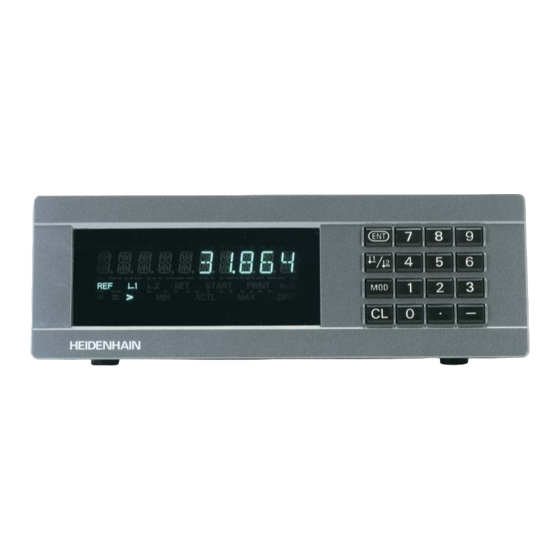
- Page 2 Display of actual value and input Numeric keypad (8 decades with algebraic sign) with decimal point SET START PRINT inch < > ACTL DIFF – HEIDENHAIN Status display with indicators...
- Page 3 Function Indicator Meaning • Set datum If the decimal points are also blinking: • Transfer input value Display is waiting for reference mark • Set display to value from P79 (P80!) traversing. If decimal points are not blinking: • Leave parameter list Reference mark has been traversed—display stores datum points in nonvolatile memory •...
- Page 4 Items supplied with ND 282 B ND 282 B Measured value display unit, benchtop model Encoder input 11 µA Id. Nr. 344 998-xx Power cord 3 m (9.9 ft) User's Manual ND 282 B Adhesive plug-in feet For stacking ND 282 B units This manual is for the ND 282 B measured value display with the following software number or higher: 354 394-01...
-
Page 5: Table Of Contents
Contents Working with the ND Display Units Encoders and Reference Marks Switch-On, Traversing the Reference Marks Datum Setting Finding Minimum and Maximum Values Sorting and Tolerance Checking Measured Value Output Error Messages Installation and Specifications Rear Panel, Accessories Mounting Power Connection Operating Parameters List of Operating Parameters Linear Encoders... -
Page 6: Encoders And Reference Marks
The ND 282 B display unit is designed for use with photo- electrical linear encoders with 11 µA sinusoidal signals: primarily for HEIDENHAIN MT length gauges with 11 µA Scale in Distance-coded The MT length gauges have one reference mark. The scales... -
Page 7: Switch-On, Traversing The Reference Marks
REF Mode Switch-On, Traversing the Reference Marks ä Crossing over the reference marks automatically switches the Turn on the power. display to REF mode: The last assignment of display values to (Switch located on rear panel.) length gauge positions is stored in nonvolatile memory. •... -
Page 8: Datum Setting
Datum Setting The datum setting procedure assigns a display value to a known position. With the ND 200 series, you can set two separate datum points. There are several ways to set the datum: • Enter a numerical value, or •... -
Page 9: Finding Minimum And Maximum Values
Finding Minimum and Maximum Values from a Series of Measurements After a series of measurements has been started, the display transfers the first measured value to the memory for minimum and maximum values. Every 0.55 ms, the display compares the current measured value with the memory contents: A new value is stored if it is greater than the stored maximum value or ACTL... - Page 10 Starting a series of measurements Switching between MIN, MAX, DIFF and ACTL displays It is not possible to switch between the displays as Repeatedly Select the display for a series of meas- described below if the switching input for external urements.
- Page 11 Starting a new series of measurements Repeatedly Select the indicator START. The indicator START blinks. START Start a new series of measurements. Ending a series of measurements Repeatedly Select the active indicator (MIN, ACTL, MAX, DIFF). The indicator that lit up last blinks. End the series of measurements.
-
Page 12: Sorting And Tolerance Checking
Sorting and Tolerance Checking In the sorting and tolerance checking mode, the display unit compares the displayed value with the programmed upper and lower sorting limits. The sorting and tolerance checking mode is enabled and disabled with operating parameter P17. Part 1 Entering sorting limits Accept... -
Page 13: Measured Value Output
Measured Value Output For technical information on the BCD data inter- face (X33), information on the data format, etc., see the chapter “BCD Interface (X33).” Measured values can be output over the BCD interface (X33). There are several ways to start measured value output: ä... - Page 14 Data Output and Display Freeze with Measured Value Output The effect of the measured value output signal on the data output is determined with operating parameter P55. Concurrent, no display freeze: The data output ignores latch commands • and always displays the current measured value (BCD ACTL.). Frozen / hold: Data output is stopped and the measured value is retained until •...
-
Page 15: Error Messages
Error Messages Display Display Display Effect/Cause BCD Output Display Effect/Cause BCD Output Checksum error: Check the datum, Last measured value not yet ERR. MEMORY BCD SPEED operating parameters and compen- called (with external data sation values for non-linear axis error requesting). -
Page 16: Rear Panel, Accessories
D-sub connection Ports X1, X33 and X41 comply with the recommendations in EN 50 178 for separation from line power. Encoder input X1 HEIDENHAIN flange socket 9-pin Input signals 11 µA Maximum encoder cable length 30 m (98.5 ft) Power switch... -
Page 17: Mounting
Mounting 172 ± 0.2 6.77 ± .008" You can fasten the ND 282 B from below by using M4 screws (see illustration at right). Hole positions for mounting the ND display unit ND 282 B display units are stackable. Adhesive plug-in feet (supplied with your unit) prevent the stacked units from being moved out of place. -
Page 18: Power Connection
Power Connection ND 282 B The rear panel of the ND 282 B contains a connecting jack for a power cord with Euro connector (power cord supplied with the delivery). Minimum cross section of the power cord: 0.75 mm Power supply: 100 Vac to 240 Vac (–15% to +10%) Power supply: 50 Hz to 60 Hz (±... -
Page 19: Operating Parameters
To access a user parameter ... Operating Parameters ... after switching on the display: Operating parameters allow you to modify the operating characteristics of your ND display unit and define the While ENT ... CL is evaluation of the encoder signals. Display first user parameter. - Page 20 Code number for changing protected operating Functions for changing the operating parameters parameters Function Page forward If you wish to change protected operating parameters, you in the list of operating parameters must first enter the code number 9 51 48: ä...
-
Page 21: List Of Operating Parameters
Distance-coded with 500 • SP (SP: signal period) 500 SP Display equal to output DISPL. BCD Distance-coded with 1000 • SP (e.g. for HEIDENHAIN LS ...C) 1000 SP Distance-coded with 2000 • SP 2000 SP Distance-coded with 5000 • SP 5000 SP... - Page 22 Parameter Settings / Function Parameter Settings / Function Reference mark evaluation Behavior without latch signal P57 BCD P44 REF Evaluate the reference mark Data output always active REF. ON TRIST. ON Do not evaluate the reference High-impedance output (3-state) TRIST. OFF mark REF.
- Page 23 Parameter Settings / Function Parameter Settings / Function External REF P85 EXT.REF Conversational language P98 LANGUA. REF over D-sub port EXT EXT.REF ON German LANGUAGE D English LANGUAGE GB No REF over D-sub port EXT EXT.REF OFF French LANGUAGE F First indicator after pressing MOD P86 MOD Italian...
-
Page 24: Linear Encoders
Linear Encoders The ND 282 B display unit is designed for use together with photoelectrical encoders with 11 µA sinusoidal signals. Display step with linear encoders You can select a specific display step by adapting the following operating parameters: • Subdivision (P32) •... - Page 25 Recommended parameter settings for HEIDENHAIN linear encoders with 11 µA signals Model Reference Millimeters Inches marks Display Display step step in mm in inches P 32 P 43 P 33 P 38 P 33 P 38 Single 0,0005 0,00002 MT xx01...
- Page 26 Recommd. parameter settings for HEIDENHAIN linear encoders with 11 µA signals (conti- nued) Model Reference Millimeters Inches marks Display Display step step in mm in inches P 32 P 43 P 33 P 38 P 33 P 38 LS 106/106C...
-
Page 27: Bcd Interface (X33)
Algebraic sign (MIN/MAX/DIFF display values are not shown) Ready message Display value You can order a connecting cable (to a PC, for example) from HEIDENHAIN (Id. Nr. 206 420-..); maximum cable length 10 m. £ £ Output Level Low: U... - Page 28 Signal run times EXT(X41) The times in the following table are guide lines. If you are working with slow data output and are using display Pin 23 functions at the same time (e.g. measurement series or inch display), the actual signal run times can be twice as long as given here. Pin 1(0V) Concurrent Data Output (P55 ACTL) Operating...
-
Page 29: Switching Inputs And Outputs Ext (X41)
Switching Inputs and Outputs EXT (X41) Inputs at D-sub connection EXT (X41) Function Danger to internal components! Voltage sources for external circuitry must conform 1, 10 to the recommendations in EN 50 178 for low- Reset display to zero, clear error message voltage electrical separation. - Page 30 Inputs Outputs Input signals Output signals Internal pull-up resistor 1 k , active with low level Open collector outputs, active with low level £ Trigger by making contact against 0 V or Delay until signal output: t 30 ms ³ by low level signal over TTL logic device Signal duration of zero signal, trigger limit A1, A2: t 180 ms...
- Page 31 Setting and zero resetting the display With an external signal, you can set the display to the value selected in parameter P79 (pin 3) or reset each axis to zero (pin 2). Enabling and disabling REF mode Operating parameter P85 allows you to activate the input (pin 25) which will be used for setting the display externally to REF mode when the unit is switched on or when the power is restored after an interruption.
- Page 32 Switching signals Output As soon as the trigger points defined in parameters are reached, the corresponding outputs (pins 15, 16) are activated. You can set up to two trigger points. The switching point “zero” has a separate output (see “Zero crossover”). Path Switching point Signals for sorting and tolerance checking...
- Page 33 Switching signal for errors The display unit permanently monitors functions such as measuring signal, input frequency, and data output, and displays an error message if it detects an error. If errors occur that seriously influence measurement or data ERROR xx Error output, the display unit activates a switching output.
-
Page 34: Distance-To-Go Mode
Function of switching outputs A1 and A2 Distance-to-Go Display Mode In the distance-to-go mode, switching outputs A1 (pin 15) and Normally, the display shows the actual position of the en- A2 (pin 16) have a different function: they are symmetrical to coder. -
Page 35: Displaying The Software Version
Displaying the Software Version To display the software version of the display unit, enter the code number 66 55 44: ➤ Select the user parameter P00 CODE. ➤ Enter the code number 66 55 44. ➤ Confirm your entry with ENT. ➤... -
Page 36: Locking The Keypad
Locking the Keypad You can disable or re-enable the keypad by entering the code number 24 65 84: ➤ Select the user parameter P00 CODE (see “Operating Parameters”). ➤ Enter the code number 24 65 84. ➤ Confirm the entry with ENT. ➤... -
Page 37: Specifications
Specifications Housing ND 282 B Noise immunity As per VDE 0843 Parts 2 and 4, Benchtop design, severity 4 cast-metal housing (W · H · D) Protection IP40 according to IEC 529 239 mm · 84.6 mm · 224 mm Encoder inputs For linear encoders with sinusoidal Operating temperature 0°... - Page 38 ND 282 B: Dimensions in mm/inches REF 1 SET START PRINT inch < = > MIN ACTL MAX DIFF 172 ± 0.2 33.5 6.77" ± .008" 1.37" 9.41"...
- Page 39 DR. JOHANNES HEIDENHAIN GmbH Dr.-Johannes-Heidenhain-Straße 5 83301 Traunreut, Germany { + 49 / 86 69 / 31-0 | + 49 / 86 69 / 50 61 e-mail: info@heidenhain.de { Service + 49 / 86 69 / 31-12 72 { TNC-Service + 49 / 86 69 / 31-14 46 | + 49 / 86 69 / 98 99 e-mail: service@heidenhain.de...
Need help?
Do you have a question about the ND 282B and is the answer not in the manual?
Questions and answers