Table of Contents
Advertisement
Advertisement
Table of Contents

Subscribe to Our Youtube Channel
Related Manuals for Circutor CVM-E3-MINI


Summary of Contents for Circutor CVM-E3-MINI
- Page 1 Power analyzer CVM-E3-MINI INSTRUCTION MANUAL (M170B01-03-18B)
- Page 2 CVM-E3-MINI Instruction Manual...
-
Page 3: Safety Precautions
CIRCUTOR, SA reserves the right to modify features or the product manual without prior notifi cation. DISCLAIMER CIRCUTOR, SA reserves the right to make modifi cations to the device or the unit specifi ca- tions set out in this instruction manual without prior notice. -
Page 4: Table Of Contents
CVM-E3-MINI CONTENTS SAFETY PRECAUTIONS ��������������������������������������������������������������������������������������������������������������������������������������� 3 DISCLAIMER ����������������������������������������������������������������������������������������������������������������������������������������������������������3 CONTENTS �������������������������������������������������������������������������������������������������������������������������������������������������������������4 REVISION LOG �������������������������������������������������������������������������������������������������������������������������������������������������������6 SYMBOLS ���������������������������������������������������������������������������������������������������������������������������������������������������������������6 1�- VERIFICATION UPON RECEPTION ����������������������������������������������������������������������������������������������������������������� 7 2�- PRODUCT DESCRIPTION �������������������������������������������������������������������������������������������������������������������������������� 7 3�- DEVICE INSTALLATION ����������������������������������������������������������������������������������������������������������������������������������� 8 3�1�- PRIOR RECOMMENDATIONS������������������������������������������������������������������������������������������������������������������� 8 3�2�- INSTALLATION ������������������������������������������������������������������������������������������������������������������������������������������ 9 3�3�- PANEL MOUNTING ACCESSORY (72 x 72 mm)�������������������������������������������������������������������������������������� 9 3�4�- DEVICE TERMINALS �������������������������������������������������������������������������������������������������������������������������������... - Page 5 CVM-E3-MINI 6�17�3� CONNECTION TIME DELAY ���������������������������������������������������������������������������������������������������������� 49 6�17�4� HYSTERESIS VALUE ��������������������������������������������������������������������������������������������������������������������� 50 6�17�5� LATCH �������������������������������������������������������������������������������������������������������������������������������������������� 50 6�17�6� DISCONNECTION TIME DELAY ��������������������������������������������������������������������������������������������������� 51 6�17�7� CONTACT STATUS ������������������������������������������������������������������������������������������������������������������������ 51 6�17�8� KILOWATTS PER PULSE �������������������������������������������������������������������������������������������������������������� 52 6�17�9� PULSE WIDTH ������������������������������������������������������������������������������������������������������������������������������� 52 6�18�- OPERATING MODE OF DIGITAL INPUT �������������������������������������������������������������������������������������������� 53 6�19�- BACKLIGHT, TURNING ON THE BACKLIT DISPLAY ������������������������������������������������������������������������...
-
Page 6: Revision Log
CVM-E3-MINI REVISION LOG Table 1: Revision log� Date Revision Description 12/17 M170B01-03-17A Initial Version Changes in the following sections: 02/18 M170B01-03-18A 3.3. - 6.17.- 10. Changes in the following sections: 04/18 M170B01-03-18B 3.2.- 3.5. - 5.1.5 - 7.3.6. SYMBOLS Table 2: Symbols... -
Page 7: 1�- Verification Upon Reception
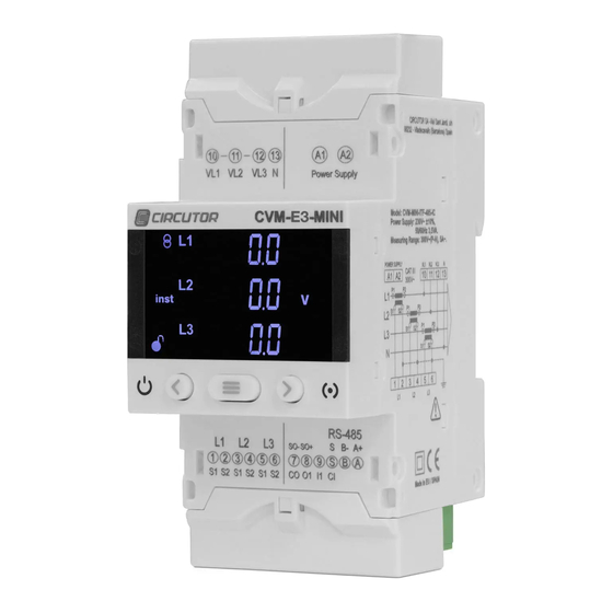
CIRCUTOR's after-sales service. 2�- PRODUCT DESCRIPTION The CVM-E3-MINI device measures, calculates and displays the main electrical parameters of the following networks: single-phase, two-phase, with and without neutral, balanced three- phase, with ARON measurements or unbalanced. The measurement will be taken in RMS with the three AC voltage inputs and three current inputs. -
Page 8: 3�- Device Installation
The CVM-E3-MINI device must be installed by authorised and qualified staff. The power supply plug must be disconnected and measuring systems switched off before handling, altering the connections or replacing the device. -
Page 9: 3�2�- Installation
3.3.- PANEL MOUNTING ACCESSORY (72 x 72 mm) Note: The 72 x 72 mm panel mounting accessory is an accessory that is sold separately. CIRCUTOR has a panel mounting accessory of the CVM-E3-MINI equipment so that it can be installed on 72 x 72 mm panels. - Page 10 CVM-E3-MINI Figure 2: Installation of the panel mounting accessory� Table 3: Technical features� Technical features Protection degree IP40 Enclosure Self-extinguishing V0 plastic 68 mm 68 mm Figure 3: Panel cut-out� Instruction Manual...
-
Page 11: 3�4�- Device Terminals
L1 current input 9: I1, Digital input 1 or selection rate 2: S2, L1 current input 8: O1, Digital output 1 3: S1, L2 current input 7: CO, Common digital outputs Figure 4:CVM-E3-MINI terminals: Up� Figure 5:CVM-E3-MINI terminals: down� Instruction Manual... -
Page 12: 3�5�- Connection Diagram
CVM-E3-MINI 3.5.- CONNECTION DIAGRAM 3�5�1�- MEASURING THREE-PHASE NETWORKS WITH A 4-WIRE CONNECTION Measurement system: 4-3Ph Alimentación Auxiliar Power Supply P2 S1 P2 S1 CARGA / LOAD Figure 6: Three-Phase measuring with a 4-wire connection� To guarantee the insulation of the device and its category, it is nec- essary to earth the S2 terminals of the transformers. -
Page 13: 3�5�2�- Measuring Three-Phase Networks With A 3-Wire Connection
CVM-E3-MINI 3�5�2�- MEASURING THREE-PHASE NETWORKS WITH A 3-WIRE CONNECTION� Measurement system: 3-3Ph Alimentación Auxiliar Power Supply P2 S1 P2 S1 CARGA / LOAD Figure 7: Three-Phase measuring with a 3-wire connection� To guarantee the insulation of the device and its category, it is nec- essary to earth the S2 terminals of the transformers. -
Page 14: 3�5�3�- Measuring Three-Phase Networks With A 3-Wire Connection And Transformers With An Aron Connection
CVM-E3-MINI 3�5�3�- MEASURING THREE-PHASE NETWORKS WITH A 3-WIRE CONNECTION AND TRANSFORMERS WITH AN ARON CONNECTION Measurement system: 3-ArOn Alimentación Auxiliar Power Supply CARGA / LOAD Figure 8: Three-Phase measuring with a 3-wire connection and transformers with an ARON connection� To guarantee the insulation of the device and its category, it is nec- essary to earth the S2 terminals of the transformers. -
Page 15: 3�5�4�- Measuring Two-Phase Networks With A 3-Wire Connection
CVM-E3-MINI 3�5�4�- MEASURING TWO-PHASE NETWORKS WITH A 3-WIRE CONNECTION Measurement system: 3-2Ph Alimentación Auxiliar Power Supply P2 S1 CARGA / LOAD Figure 9: Measuring Two-Phase Networks with a 3-wire connection� To guarantee the insulation of the device and its category, it is nec- essary to earth the S2 terminals of the transformers. -
Page 16: 3�5�5�- Measuring Single-Phase Networks, Phase To Phase, With A 2-Wire
CVM-E3-MINI 3�5�5�- MEASURING SINGLE-PHASE NETWORKS, PHASE TO PHASE, WITH A 2-WIRE CONNECTION� Measurement system: 2-2Ph Alimentación Auxiliar Power Supply CARGA / LOAD Figure 10: Measuring Single-Phase Networks, phase to phase, with a 2-wire connection� To guarantee the insulation of the device and its category, it is nec- essary to earth the S2 terminals of the transformers. -
Page 17: 3�5�6�- Measuring Single-Phase Networks, Phase To Neutral, With A 2-Wire
CVM-E3-MINI 3�5�6�- MEASURING SINGLE-PHASE NETWORKS, PHASE TO NEUTRAL, WITH A 2-WIRE CONNECTION� Measurement system: 2-1Ph Alimentación Auxiliar Power Supply CARGA / LOAD Figure 11: Measuring Single-Phase Networks, phase to neutral, with a 2-wire connection� To guarantee the insulation of the device and its category, it is nec- essary to earth the S2 terminals of the transformers. -
Page 18: 4�- Operation
CVM-E3-MINI 4�- OPERATION The CVM-E3-MINI is a four-quadrant power analyzer (consumption and generation). The device can operate according to three different measurement conventions: CIRCUTOR measurement convention. IEC measurement convention. IEEE measurement convention. The measurement convention is configured in the setup menu, see “6.6. -
Page 19: 4�1�- Measuring Parameters
P < 0 Q < 0 P > 0 Q < 0 Figure 14:IEEE measurement convention� 4.1.- MEASURING PARAMETERS The device displays the electrical parameters shown in Table 5 Table 5: Measuring parameters of the CVM-E3-MINI Phases Total Maxim� Minim� Parameter... - Page 20 CVM-E3-MINI Table 5 (Continuation) : Measuring parameters of the CVM-E3-MINI� Phases Total Maxim� Minim� Parameter Units L1-L2-L3 value value Harmonic Breakdown - Current harm V (up to the 31st order harmonic) Total Active Energy M/kWh (Consumption and Generation)
-
Page 21: 4�2�- Keyboard Functions
CVM-E3-MINI 4.2.- KEYBOARD FUNCTIONS The CVM-E3-MINI has 3 keys that allow you to browse between the various screens and pro- gram the device. Key functions on measuring screens ( Table 6 Table 6: Key functions on measuring screens� Short keystroke... -
Page 22: 4�3�- Display
The display is divided into two areas ( Figure 15 Data area States area Figure 15: CVM-E3-MINI Display areas The data area displays the values measured or calculated by the device. The device states area shows the different states, profiles and information about the unit ( Table 10 Table 10: Icons in the display�... -
Page 23: 4�4�- Led Indicators
ALARM / ENERGY PULSES Figure 16:LED Indicators of the CVM-E3-MINI� 4.5.- DIGITAL INPUT The CVM-E3-MINI has one digital input (terminals S and 9 on ) that can be programmed Table 4 to operate as a logic or tariff selection input. -
Page 24: 4�6�- Digital Output
CVM-E3-MINI 4.6.- DIGITAL OUTPUT The device has one digital output, optoisolated NPN transistors (terminals 8 and 7 on Table 4 fully programmable, see “6.17. PROGRAMMING ALARM : DIGITAL OUTPUT T1” Press the keys to access the digital output status screen, see “5.4.- DIGITAL INPUT... -
Page 25: 5�- Display
CVM-E3-MINI 5�- DISPLAY The CVM-E3-MINI has 2 operation profiles. The display screens will be opened for the corre- sponding profile: Analyzer profile, analyzer, Electrical energy efficiency profile, e Press the key to change from one operating profile to another. - Page 26 CVM-E3-MINI Table 12 (Continuation) : Analyzer profile screens� Screen Parameters (units) Current L1 (A) Current L2 (A) Current L3 (A) Active Power L1 (M/kW) Active Power L2 (M/kW) Active Power L3 (M/kW) Apparent Power L1 (M/kVA) Apparent Power L2 (M/kVA)
- Page 27 CVM-E3-MINI Table 12 (Continuation) : Analyzer profile screens� Screen Parameters (units) Active Power III (M/kW) Apparent Power III (M/kVA) Capacitive Reactive Power III (M/kvar Cos φ L1 (cos φ) Cos φ L2 (cos φ) Cos φ L3 (cos φ) Power factor L1 (PF)
-
Page 28: 5�1�1�- Maximum Values
CVM-E3-MINI 5�1�1�- MAXIMUM VALUES To see the maximum values of the screen being displayed, press the key for 2 seconds. These are displayed for 10 seconds. Press the keys to display all other maximum values. The max symbol is shown on the display. -
Page 29: 5�1�5�- Detection Of Incorrect Connection And Incorrect Direction Of Rotation
CVM-E3-MINI The harmonics display screens can be displayed by pressing the key shown after the last profile screen. Harmonics are represented as shown in . The figure shows the 15th voltage harmonic Figure 17 (H15). Figure 17: 15th voltage harmonic�... -
Page 30: E 3 Profile
CVM-E3-MINI 5.2.- e PROFILE The installation’s consumed and generated energy are displayed on the e profile of the device. The installation status is also displayed: Installation is consuming energy. Installation is generating energy. Long press (3 sec.) the keys to jump from the generated values to the consumed values displayed. - Page 31 CVM-E3-MINI Table 13 (Continuation) : Screens of the e profile� Screen Parameters (units) Total three-phase Capacitive Reactive Energy (kvar Total Cost (cost) Total CO Emissions (kgCO Total No. of hours (hours) Three-phase Active Energy Tariff 1 (kWh) Three-phase Apparent Energy Tariff 1 (kVAh)
- Page 32 CVM-E3-MINI Table 13 (Continuation) : Screens of the e profile� Screen Parameters (units) Three-phase Inductive Reactive Energy Tariff 1 (kvar Three-phase Capacitive Reactive Energy Tariff 1 (kvar Cost Tariff 1 (cost) Emissions Tariff 1 (kgCO No. of hours Tariff 1 (hours)
- Page 33 CVM-E3-MINI Table 13 (Continuation) : Screens of the e profile� Screen Parameters (units) Three-phase Apparent Energy Tariff 2 (kVAh) Three-phase Inductive Reactive Energy Tariff 2 (kvar Three-phase Capacitive Reactive Energy Tariff 2 (kvar Cost Tariff 2 (cost) Emissions Tariff 2 (kgCO No.
-
Page 34: 5�3�- Device Information Screens
CVM-E3-MINI 5.3.- DEVICE INFORMATION SCREENS Press the keys at the same time on any display screen to open the device infor- mation screens, with the version and serial number of the device ( Figure 18 Figure 18: Device information screens�... -
Page 35: 6�- Configuration
CVM-E3-MINI 6�- CONFIGURATION To enter the configuration menu press the key for 3 seconds. If the icon appears on the configuration screen, the configuration parameters can be edited. If the icon appears, the configuration of the unit will be locked with a password (“... -
Page 36: 6�1�- Primary Voltage
CVM-E3-MINI 6.1.- PRIMARY VOLTAGE On this screen the voltage transformer primary is programmed. Press the key for 3 seconds to enter the edit mode. The prog icon will flash on the left of the screen. Press the key to modify the value of the flashing digit. -
Page 37: 6�3�- Primary Current
CVM-E3-MINI When the desired value is shown on the screen, use the keys to move the edit cursor. To validate the value, press the key for 3 seconds; the prog icon will stop flashing. If the value entered by the user is out of the range of programming values, the programmed value will be deleted and the system will restore it to the last saved value. -
Page 38: 6�4�- Secondary Current
CVM-E3-MINI 6.4.- SECONDARY CURRENT On this screen the current transformer secondary is selected. key for 3 seconds to enter the edit mode. The prog icon will flash on the left Press the of the screen. Voltage ratio x Primary Current ≤ 300000. -
Page 39: 6�6�- Measurement Convention
3 seconds to enter the edit mode. The prog icon will flash on the left of the screen. The key is used to browse the different options: Cir Circutor measurement convention. IEC IEC measurement convention. IEEE IEEE measurement convention. To validate the value, press the key for 3 seconds;... -
Page 40: 6�8�- Maximum Demand Integration Period
CVM-E3-MINI key for 3 seconds; the prog icon will stop flashing. To validate the value, press the Press key to access the next programming step. 6.8.- MAXIMUM DEMAND INTEGRATION PERIOD The maximum demand integration period is programmed in minutes on this screen. -
Page 41: 6�9�- Deleting Maximum Demand
CVM-E3-MINI 6.9.- DELETING MAXIMUM DEMAND On this screen you select whether or not to delete the maximum demand. key for 3 seconds to enter the edit mode. The prog icon will flash on the left Press the of the screen. -
Page 42: 6�11�- Deleting Energy Values
CVM-E3-MINI 6.11.- DELETING ENERGY VALUES On this screen you select whether or not to delete the energy, cost, CO emissions and No. of hours values key for 3 seconds to enter the edit mode. The prog icon will flash on the left Press the of the screen. -
Page 43: Carbon Emission Ratio Of Consumed Energy
CVM-E3-MINI 6.13.- kgC0 CARBON EMISSION RATIO OF CONSUMED ENERGY The carbon emissions ratio is the amount of emissions released into the atmosphere to produce a unit of electricity (1 kWh). The ratio for the European mix is approximately 0.65 kgCO per kWh. -
Page 44: 6�15�- Cost Ratio Of Consumed Energy
CVM-E3-MINI 6.14.- kgC0 CARBON EMISSION RATIO OF GENERATED ENERGY The carbon emissions ratio is the amount of emissions released into the atmosphere to produce a unit of electricity (1 kWh). The ratio for the European mix is approximately 0.65 kgCO per kWh. -
Page 45: 6�16�- Cost Ratio Of Generated Energy
CVM-E3-MINI key for 3 seconds to enter the edit mode. The prog icon will flash on the left Press the of the screen. Press the key to modify the value of the flashing digit. When the desired value is shown on the screen, use the keys to move the edit cursor. -
Page 46: 6�17�- Programming Alarm : Digital Output T1
CVM-E3-MINI 6.17.- PROGRAMMING ALARM : DIGITAL OUTPUT T1 The values corresponding to digital output T1 are programmed in this step. The code of the variable is selected on this screen, according to Table 14 Table 15 Table , which will control digital output T1. - Page 47 CVM-E3-MINI Table 14 (Continuation) : Parameter codes used to program the digital output (Table 1)� Parameter Phase Code Phase Code Phase Code Phase Code Apparent Power Maximum Demand Inductive Power Maximum Demand Capacitive Power Maximum Demand In addition, there are some parameters (...
-
Page 48: 6�17�1� Maximum Value
CVM-E3-MINI 6�17�1� MAXIMUM VALUE This screen is used to programme the maximum value, i.e., the value above which the alarm will be activated. Press the key for 3 seconds to enter the edit mode. The prog icon will flash on the left of the screen. -
Page 49: 6�17�3� Connection Time Delay
CVM-E3-MINI to a value higher than 9. When the desired value is shown on the screen, use the keys to move the edit cursor. Note: Pay special attention when programming the Generation Power (displayed with negative values). Example: If you wish to enter a generation power alarm with limits between 2 kW and 1 kW, program the following as the maximum value : - 1 kW and the following as the minimum value : - 2 kW. -
Page 50: 6�17�4� Hysteresis Value
CVM-E3-MINI 6�17�4� HYSTERESIS VALUE The hysteresis value, i.e., difference between the alarm connection and disconnection value, in %, is programmed on this screen. Press the key for 3 seconds to enter the edit mode. The prog icon will flash on the left of the screen. -
Page 51: 6�17�6� Disconnection Time Delay
CVM-E3-MINI 6�17�6� DISCONNECTION TIME DELAY The alarm disconnection delay is programmed on this screen in seconds. Press the key for 3 seconds to enter the edit mode. The prog icon will flash on the left of the screen. Press the key to modify the value of the flashing digit. -
Page 52: 6�17�8� Kilowatts Per Pulse
CVM-E3-MINI 6�17�8� KILOWATTS PER PULSE Note: This screen is displayed if the alarm parameter has been selected from an energy value, Table 16 This screen is used to programme the kilowatts per pulse. Press the key for 3 seconds to enter the edit mode. The prog icon will flash on the left of the screen. -
Page 53: 6�18�- Operating Mode Of Digital Input
CVM-E3-MINI Press the key to modify the value of the flashing digit. When the desired value is shown on the screen, use the keys to move the edit cursor. Maximum programming value: 500 ms. Minimum programming value: 30 ms. To validate the value, press the key for 3 seconds;... -
Page 54: 6�19�- Backlight, Turning On The Backlit Display
CVM-E3-MINI 6.19.- BACKLIGHT, TURNING ON THE BACKLIT DISPLAY This screen is used to programme the maximum brightness time of the display since the device was last used with the keypad. After this time, the display will reduce the brightness level. -
Page 55: 6�20�1�- Modbus Protocol: Baud Rate
CVM-E3-MINI Press key to browse the two options: nodb Modbus bacn BACnet. key for 3 seconds; the prog icon will stop flashing. To validate the value, press the Press key to access the next programming step. Note: The device will restart after exiting the setup menu if the RS-485 communications parameters have been modified. -
Page 56: 6�20�2�- Modbus Protocol: Peripheral Number
CVM-E3-MINI 6�20�2�- MODBUS PROTOCOL: PERIPHERAL NUMBER The peripheral number is programmed on this screen. Press the key for 3 seconds to enter the edit mode. The prog icon will flash on the left of the screen. Press the key to modify the value of the flashing digit. -
Page 57: 6�20�4�- Modbus Protocol : Data Bits
CVM-E3-MINI key for 3 seconds; the prog icon will stop flashing. To validate the value, press the Press key to access the next programming step. 6�20�4�- MODBUS PROTOCOL : DATA BITS The number of data bits of Modbus communications are programmed on this screen. -
Page 58: 6�20�6�- Bacnet Protocol : Baud Rate
CVM-E3-MINI 6�20�6�- BACnet PROTOCOL : BAUD RATE The baud rate of BACnet communications is programmed on this screen. Press the key for 3 seconds to enter the edit mode. The prog icon will flash on the left of the screen. -
Page 59: 6�20�8�- Bacnet Protocol : Mac Address
CVM-E3-MINI 6�20�8�- BACnet PROTOCOL : MAC ADDRESS The MAC address is programmed on this screen. Press the key for 3 seconds to enter the edit mode. The prog icon will flash on the left of the screen. Press the key to modify the value of the flashing digit. -
Page 60: 6�21�1�- Password
CVM-E3-MINI Figure 21: Password screen� Press the key to modify the value of the flashing digit. When the desired value is shown on the screen, use the keys to move the edit cursor. key for 3 seconds; the prog icon will stop flashing. - Page 61 CVM-E3-MINI When the desired value is shown on the screen, use the keys to move the edit cursor. To validate the password, press the key if you are on the last digit or the key if you are on the first digit.
-
Page 62: 7�- Communications
COMMUNICATIONS” 7.1.- CONNECTIONS The RS -485 cable must be wired with twisted pair cable with mesh shield (minimum 3 wires), with a maximum distance between the CVM-E3-MINI and the master device of 1200 metres. A maximum of 32 CVM-E3-MINI devices can be connected to this bus. -
Page 63: 7�2�- Modbus Protocol
CVM-E3-MINI 7.2.- MODBUS PROTOCOL In the Modbus protocol, the CVM-E3-MINI device uses the RTU (Remote Terminal Unit) mode. The Modbus functions implemented in the device are as follows: Function 0x03 and 0x04. Reading integer registers. Function 0x05. Writing a relay. -
Page 64: 7�3�- Modbus Commands
Map 2, uses the addresses of the CVM-C10 device (adding 0x1000 to all addresses). Except for 3 parameters, the CVM-C10 and the CVM-E3-MINI use the same parameters. Map 2 should be used if a Modbus map is going to be implemented from scratch. However, if the map is already being used in another device, use Map 1 for CVM-MINI and Map 2 for CVM-C10. - Page 65 CVM-E3-MINI Table 17 (Continuation) : Modbus memory Map 1: Measurement variables Mapa 1 Parameter Symbol Instantaneous Maximum Minimum Units L3 Capacitive Power kvarC 3 13A-13B 14C-14D 15E-15F L3 Apparent Power kVA 3 4E-4F AE-AF 10E-10F L3 Power Factor PF 3...
- Page 66 CVM-E3-MINI Tabla 18 (Continuation) : Modbus memory Map 2: Measurement variables Map 2 Parameter Symbol Instantaneous Maximum Minimum Units L2 Apparent Power kVA 2 101A-101B 1120-1121 117E-117F L2 Power Factor PF 2 101C-101D 1122-1123 1180-1181 x 100 Cos φ L2 Cos φ...
-
Page 67: 7�3�2� Energy Variables
CVM-E3-MINI 7�3�2� ENERGY VARIABLES All the adresses of Modbus memory are in Hexadecimal. For these variables is implemented the Function 0x03 and 0x04� Table 19: Modbus memory Map 1: Energy variables Map 1 Parameter Symbol Tariff 1 Tariff 2 Total... - Page 68 CVM-E3-MINI Table 20 (Continuation) : Modbus memory Map 2: Energy variables Map 2 Parameter Símbolo Tariff 1 Tariff 2 Total Units Consumed apparent energy III (VAh) kVAh III 106C-106D 1096-1097 10EA-10EB Consumed CO emissions KgCO 106E-106F 1098-1099 10EC-10ED Consumption cost...
-
Page 69: 7�3�3� Voltage And Current Harmonics
CVM-E3-MINI Table 21 (Continuation) : Modbus memory Map 1 and Map 2 (energy variables per phase) Map 1 and Map 2 Parameter Symbol Units Consumed active energy (Wh) Total 1442-1443 14A2-14A3 1502-1503 Consumed inductive reactive energy To- kvarhL 1444-1445 14A4-14A5... - Page 70 CVM-E3-MINI Table 22 (Continuation) : Modbus memory Map 1: Voltage Harmonics Map 1 Parameter Voltage L1 Voltage L2 Voltage L3 Units 27th Order harmonic 31E-31F 33E-33F 35E-35F % x 10 28th Order harmonic 320-321 340-341 360-361 % x 10 29th Order harmonic...
- Page 71 CVM-E3-MINI Table 24: Modbus memory Map 1: Current Harmonics Map 1 Parameter Current L1 Current L2 Current L3 Units Fundamental Harm. 1F4-1F5 212-213 230-231 mA x 10 2nd Order harmonic 1F6-1F7 214-215 232-233 % x 10 3rd Order harmonic 1F8-1F9...
-
Page 72: 7�3�4� Deleting Parameters
CVM-E3-MINI Table 25 (Continuation) : Modbus memory Map 2: Current Harmonics Map 2 Parameter Current L1 Current L2 Current L3 Units 11th Order harmonic 1A93 1AB3 1AD3 % x 10 12th Order harmonic 1A94 1AB4 1AD4 % x 10 13th Order harmonic... -
Page 73: 7�3�5� Power Status
CVM-E3-MINI 7�3�5� POWER STATUS All the Modbus map addresses are hexadecimal. The function 0x04 is implemented for this variable. This variable indicates the quadrant in which the device is operating. Table 27:Modbus memory map: Power status Power status Variable Address... - Page 74 CVM-E3-MINI Table 30 (Continuation) : Modbus memory map: Transformation ratios� Transformation ratios Default Configuration variable Address Valid data margin value Current primary 2713 1 - 10000 0: .../1A Current secondary 2714 1: ../5 A Voltage ratio x Current ratio ≤ 300000.
- Page 75 CVM-E3-MINI 7�3�7�6� Display backlight Table 35:Modbus memory map: Backlight Backlight Configuration variable Address Valid data margin Default value Backlight 2B5E 1 - 999 seconds 300 s 7�3�7�7� Activating the harmonics display screen Table 36:Modbus memory map: Display of harmonics Display of harmonics...
- Page 76 CVM-E3-MINI Table 39 (Continuation) : Modbus memory map: Programming Digital Output T1 (Alarm) Programming Digital Output : Alarm Configuration variable Address Valid data margin Default value 0 : Normally open Contacts status 2B01 1: Normally closed Table 40:Modbus memory map: Programming Digital Output T1 (pulses output)
- Page 77 CVM-E3-MINI Table 45:Variable format: Status of the digital outputs� Bit 7 Bit 6 Bit 5 Bit 4 Bit 3 Bit 2 Bit 1 Bit 0 Output 1 0: OFF 1: ON 7�3�7�13� Communications Table 46:Modbus memory map: Communications Communications Default...
-
Page 78: 7�4�- Bacnet Protocol
CVM-E3-MINI 7.4.- BACnet PROTOCOL BACnet is a communications protocol for Building Automation and Control NETworks. This protocol replaces the proprietary communications of each device, making it a set of common communication rules that enables the complete integration of the building automation and control devices of different manufacturers. -
Page 79: 7�4�1�- Mapa Pics
CVM-E3-MINI 7�4�1�- MAPA PICS PICS Vendor Name: CIRCUTOR Product Name: CVM-E3-MINI Product Model Number: Application Software Version: Firmware Revision: 0.7.1 BACnet Protocol Revision: 10 Product Description: Electrical energy meter BACnet Standardized Device Profile (Annex L) BACnet Application Specific Controller (B-ASC) - Page 80 CVM-E3-MINI DESCRIPTION SYMBOL ID OBJECTS OBJECT NAME UNITS Potencia activa Active power kW 2 ActPwrPh2 Potencia reactiva Reactive power kvar 2 ReactPwrPh2 kvar Factor de potencia Power factor PF 2 PwrFactPh2 Tensión fase-neutro Voltage phase to AI10 Ph2NU3 neutral Corriente...
- Page 81 CVM-E3-MINI DESCRIPTION SYMBOL ID OBJECTS OBJECT NAME UNITS Potencia aparente L3 Aparent power L3 AI42 AppPwrPh3 Potencia aparente Three phase aparent kVAIII AI43 AppPw3Ph trifásica power Máxima demanda I1 Maximum demand I1 Md (A1) AI44 MaxDemand_A1 Máxima demanda I2 Maximum demand I2...
-
Page 82: 8�- Technical Features
CVM-E3-MINI 8�- TECHNICAL FEATURES AC Power supply Rated voltage 207 ... 253 V Frequency 50 ... 60 Hz Consumption 3.5 VA Installation category CAT III 300 V Voltage measurement circuit Rated voltage (Un) 300 V , 520 V Ph-N Ph-Ph Voltage measurement margin 5 ... - Page 83 CVM-E3-MINI Communications Modbus RTU BACnet RS-485 MS/TP Protocol Modbus RTU BACnet Baud rate 9600 - 19200 - 38400 - 57600 bps 9600 - 19200 - 38400 bps Stop bits 1 - 2 Parity without - even - odd without User interface...
- Page 84 CVM-E3-MINI 52.5 Figure 23: Dimensions of the CVM-E3-MINI� Instruction Manual...
-
Page 85: 9�- Maintenance And Technical Service
• CIRCUTOR accepts no liability due to the possible damage to the unit or other parts of the installation, nor will it cover any possible sanctions derived from a pos- sible failure, improper installation or “improper usage”... -
Page 86: 11�- Ce Certificate
CVM-E3-MINI 11�- CE CERTIFICATE Instruction Manual... - Page 87 CVM-E3-MINI Instruction Manual...
- Page 88 CVM-E3-MINI Instruction Manual...
- Page 89 CVM-E3-MINI Instruction Manual...
- Page 90 CIRCUTOR, SA Vial Sant Jordi, s/n 08232 -Viladecavalls (Barcelona) Tel.: (+34) 93 745 29 00 - Fax: (+34) 93 745 29 14 www.circutor.com central@circutor.com...
Need help?
Do you have a question about the CVM-E3-MINI and is the answer not in the manual?
Questions and answers