
Related Manuals for Circutor CVM k2


Summary of Contents for Circutor CVM k2
- Page 1 Three-phase power analyzer and power quality USER's MANUAL (M98206501-03-10B) 1ZD4...
- Page 2 CVM k 2 ADVERTENCIAS / SIMBOLOS Una conexión incorrecta del equipo puede producir la muerte, lesiones PELIGRO graves y riesgo de incendio. Lea y entienda el manual antes de conectar el equipo. Observe todas las instrucciones de instalación y operación durante el uso de este instrumento.
- Page 3 CVM k 2 AVERTISSEMENT / SYMBOLES Un branchement incorrect de l’appareil peut entraîner la mort ou des lésions DANGER graves et peut provoquer un incendie. Avant de brancher votre appareil, lisez attentivement le manuel et assurez-vous de bien avoir compris toutes les explications données.
- Page 4 CVM k 2 WARNHINWEISE / SYMBOLE Durch einen nicht sachgemäßen Anschluss der Anlage können Tod, GEFAHR schwere Verletzungen und Brandrisiko hervorgerufen werden. Bevor Sie die Anlage anschließen, lesen Sie bitte das Handbuch durch und machen Sie sich dessen Inhalt klar. Beachten Sie bei Einsatz dieses Instrumentes sämtliche Installations- und Betriebshinweise.
- Page 5 CVM k 2 INDICE MANUAL 1. INTRODUCTION 1.1 DESCRIPTION ......................11 1.2 TYPES AVAILABLE ....................12 1.3 ExPANSION CARDS ..................... 13 1.4 CODING FOR OTHER PARAMETERS ..............13 1.5 ANALYSIS PARAMETERS ..................14 1.6 ACCESORIES......................14 2. INSTALLATION 2.1 ITEMS TO VERIFY UPON RECEPTION..............15 2.2 ASSEMBLY SITE .....................
- Page 6 CVM k 2 2.6.7 - 2 CT AND 2 VOLTAgE TRANSfORmERS ........... 24 2.7 POWER SUPPLY CONNECTION DIAGRAM ............24 3. OPERATION 3.1 DESCRIPTION OF DEVICE ..................25 3.1.1 fRONTAL VIEW ....................25 3.1.1.a. Display ...................... 26 3.1.1.b. Function buttons ..................26 3.1.1.c.
- Page 7 CVM k 2 4.7.2.2. Relay outputs configuration ..............50 4.7.2.3. Digital inputs configuration ............... 51 4.7.2.4. Card Connections ..................52 4.7.2.5. Expansion card parameters ..............53 4.7.2.6. Features ....................53 4.7.3 - 8 ANALOgUE INPUTS AND 4 ANALOgUE OUTPUTS ....... 54 4.7.3.1.
- Page 8 CVM k 2 4.7.7.2. Card parameters ..................73 4.7.7.3. Slave number configuration ..............74 4.7.7.4. Leds information ..................75 4.7.7.5. Profibus connector ..................75 4.7.7.6. gSD modules ................... 76 5. OTHER SYSTEM CONFIGURATIONS 5.1 PREFERENCES ...................... 77 5.1.1 SCREEN ......................77 5.1.2 CLOCK / TEmPERATURE ................
- Page 9 CVM k 2 6.1.5.4 Apparent Power ..................98 6.1.5.5 Total Power....................99 6.1.6, POWER fACTOR ..................100 6.1.7 COS ......................100 6.2. DEMAND ......................103 6.3 ENERGY ....................... 104 6.3.1 PRESENT ENERgy ..................104 6.3.2 mONTH ENERgy ..................105 6.3.3 yEARLy ENERgy ..................105 6.4 ExPANSION CARDS ...................
- Page 10 CVM k 2 8.2. CONNECTION DIAGRAM ..................124 8.2.1. CIRCUTOR INTELLIgENT CONVERTER ............ 124 8.2.2. TCP2RS CONVERTER ................. 125 8.2.3. USB CONVERTER ..................126 8.2.4 SCREEN-mODULES COmmUNICATIONS BUS ........... 127 8.3. MODBUS/RTU © MEMORY MAP ................ 128 8.3.1 ELECTRIC VARIABLES ................128 8.3.2.
-
Page 11: Description
• 8 digit (100 gW·h) counter to track energy consumed and energy generated. • Recording of power supply quality events on voltage. • Expandable with inputs/outputs expansion card. • Implemented in the CIRCUTOR energy management software, PowerStudio Scada. http://powerstudio.circutor.com (*) Depending on the model... -
Page 12: Types Available
CVM k 2 CVmk2 has no battery. When supply falls down the analyzer do not store electrical parmeters and no quality events. Is very important to guarantee the supply of the device from an interrupted source (Batery, SAI, ...) 1.2 TYPES AVAILABLE CODE TYPE M54400 CVM k 2-ITF-405... -
Page 13: Expansion Cards
CVM k 2 1.3 ExPANSION CARDS CVmk2 has a wide range of expansion cards that enable users to interact with the system or tocommunicate with other protocols. The expansion cards and corresponding codes are in the following table CODIGO DESCRIPCIÓN 8 opto-coupled digital inputs M54501 8I/8O... -
Page 14: Analysis Parameters
CVM k 2 1.5 ANALYSIS PARAMETERS PARAMETER UNIT L1 L2 L3 N Ph-N VOLTAgE ● ● ● ● ● Ph-Ph VOLTAgE ● ● ● ● CURRENT ● ● ● ● ● fREQUENCy ● ACTIVE POWER (Consumption and generation) ● ● ●... -
Page 15: Items To Verify Upon Reception
CVM k 2 2. INSTALLATION This manual provides information and warnings that the user should heed to guarantee that the system operates safely and is kept in good conditions for safe use. If the system is handled in a way contrary to the manufacturer's specifications, it may not be protected. -
Page 16: Installation Methods
CVM k 2 2.3 INSTALLATION METHODS The figures illustrate the different installation possibilities, permitted by the display screen design. The system design facilitates screwing the panel on (92 + 92 mm, 138 + 138 +0.8 +0.8 +0.8 mm and a 103 mm diameter hole). +0.8 The figures illustrate how to mount the front part (display) in a 92x92 mm (3,62 x 3,62 in) hole, a 103... - Page 17 CVM k 2 A zoomed view of the previous image is provided in the figure. It provides a detailed view of the movements necessary to lock and unlock CVMk2 display screen mount ring. As shown in the figure, the guide arrow should point upward and line up with the arrow found on the rear of the viewer or display screen.
-
Page 18: System Connection
CVM k 2 2.4 SYSTEM CONNECTION Before connecting the equipment, the following points should be verified: 2.3.1 Auxiliary Power Supply features 2.3.2 maximum Voltage in the Voltage measuring Circuit 2.3.3 maximum Current in the Current measuring Circuit 2.3.4 Working Conditions 2.3.5 Safety 2.4.1 AUxILIARY POWER SUPPLY Standard power supply... -
Page 19: Safety
CVM k 2 2.4.5 SAFETY Designed for CAT III 300/520 Vac installations in accordance with EN-61010. Protected against electrical shock by class II double insulation. Designed and identified by the distinctive CE marks. To increase system capacity with expansion cards prior to handling, modify its connections or replace equipment;... -
Page 20: Terminals Description
CVM k 2 2.5 TERMINALS DESCRIPTION 2.5.1 TAG FOR VOLTAGE AND CT CONNECTIONS TERMINAL DESCRIPTION Current transformer, L1 phase S1 connection Current transformer, L1 phase S2 connection Current transformer, L2 phase S1 connection Current transformer, L2 phase S2 connection Current transformer, L3 phase S1 connection Current transformer, L3 phase S2 connection Current transformer, neutral line S1 connection Current transformer, neutral line S2 connection... -
Page 21: Measuring Input Connection Diagrams
CVM k 2 2.6 MEASURING INPUT CONNECTION DIAGRAMS 2.6.1 - 4 CT AND 5 VOLTAGE REFERENCES 2.6.2 - 4 CT AND 4 VOLTAGE REFERENCES... -
Page 22: Ct And 4 Voltage References
CVM k 2 2.6.3 - 3 CT AND 4 VOLTAGE REFERENCES 2.6.4 - 3 CT AND 3 VOLTAGE REFERENCES... -
Page 23: Ct And 2 Voltage Transformers
CVM k 2 2.6.5 - 4 CT AND 2 VOLTAGE TRANSFORMERS 2.6.6 - 3 CT AND 2 VOLTAGE TRANSFORMERS... -
Page 24: Ct And 2 Voltage Transformers
CVM k 2 2.6.7 - 2 CT AND 2 VOLTAGE TRANSFORMERS 2.7 POWER SUPPLY CONNECTION DIAGRAM Power supply 85...265 V a.c. 100...300 V c.c. (Standard model) The system should be connected to a power supply circuit protected by fuses with current ratings between 0.5 and 1 A / 600 V (UL listed). It should be provided with a MCCB or equivalent device to switch off the system from the power supply circuit. -
Page 25: Description Of Device
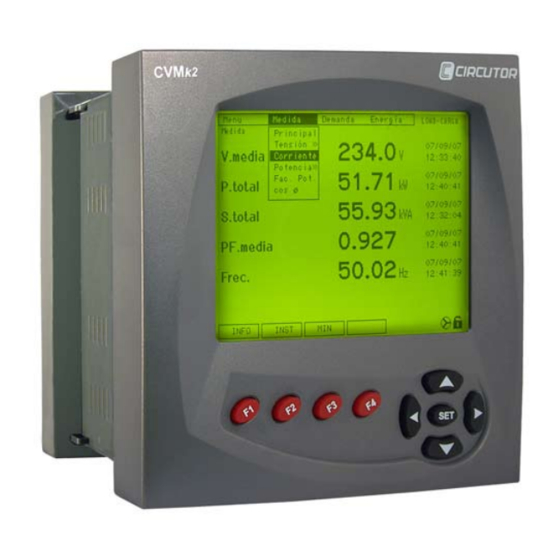
CVM k 2 3. OPERATION 3.1 DESCRIPTION OF DEVICE The external dimensions of the CVMk2 network analyzer are 144 x 144 x 116 mm. It is comprised of a display screen and a measuring module. The display screen communicates with the measuring module via an RJ-45 line, which is "transparent" or direct. The wire layout is provided in the figure below: DISPLAY SCREEN MEASURING EQUIPMENT... -
Page 26: A. Display
CVM k 2 The front is divided into several parts: a) Display screen. b) function buttons. c) Navigation buttons. button. e) Upper and lower menus. f) module name. g) Icons. 3.1.1.a. Display The CVMk2 network analyzer incorporates a 320 x 240 pixel, backlit, 1/4 VgA (QVgA) LCD monitor. -
Page 27: F. Module Name
CVM k 2 3.1.1.f. Module name The measuring module currently being viewed is defined on this part of the display screen. This is important in facilities where measuring modules are communicating with one single display screen. 3.1.1.e. Icons Editable configuration menu (without password). Configuration menu locked with password. -
Page 28: Start-Up
CVM k 2 3.2. START-UP Before power ON the device, make sure that all the cables are properly connected. A bad connection can cause serious injuries to the personnel that are working on the equipment and can damage the equipment. When power supply is connected to the CVMk2, the system will show an initial presentation and initialize its internal software indicating the firmware version on the display screen. -
Page 29: Measuring
CVM k 2 4. CONFIGURATION The analyzer does not store programming changes that are made until programming is complete. These changes are confirmed by pressing after the button. If the system is reset before said programming is complete or if the user exits the menu using the button, the configuration settings will not be stored in memory. -
Page 30: Quality
CVM k 2 Parameters that can be configured on this screen follow: • Primary on the voltage transformers. If it does not exist, PRIM. U. program . The maximum configurable value is 999999. • Secondary on the voltage transformers. If it does not exist, SEC. -
Page 31: Quality
CVM k 2 4.2.1. QUALITY To access the quality parameters configuration menu, go to the menu, in the main quality configuration menu, and select . From the two options provided, select quality quality Parameters that can be configured on this screen are: •... -
Page 32: Events
CVM k 2 • nom. v. Enter the network rated phase-neutral voltage value. If using a voltage transformer, enter the transformer secondary value. If there is no neutral line, enter the voltage value as if there was one. This is used for quality events calculations. - Page 33 CVM k 2 The cursor will be positioned over the first digit, corresponding to the largest value. Use the left/right arrow buttons to navigate from one digit to another and the up/down arrow buttons to increase/decrease the value of the digit where the cursor is currently positioned. To save the modified parameters to memory, press (f4) before exiting.
-
Page 34: Demand
CVM k 2 Another example of event are showed in times period t1, t3 and t4. They are Sags. They are configured usually unther 90% of the nominal voltage. When the voltage goes down unther 10% it is stored as an interruption. That interruption is showed in period t2. -
Page 35: Tariffs
It is possible to load a yearly fee calendar to the memory. This calendar can only be saved from the CIRCUTOR POWER STUDIO SCADA software. The calendar is stored in the memory and is synchronised with the internal clock. -
Page 36: Delete
CVM k 2 Numbers 100X correspond to the digital inputs for the expansion card inserted in slot 1. Numbers correspond to the digital inputs for the expansion card inserted in slot 2, and 200X numbers correspond to the digital inputs for the expansion card inserted in slot 3. 300X Example: you wish to configure 5 tariff and assign them to CVMk2 inputs 3, 4, 5 and 6. -
Page 37: Communications
CVM k 2 • demand Zero the maximum demand values, including those for different tariff. • : Zero accumulated pulse values for the inputs from all static digital input ext. cont. expansion cards. 4.6 COMMUNICATIONS To access the CVMk2 communications configuration, select Setup inside the Menu. -
Page 38: Expansion Cards
CVM k 2 4.7 ExPANSION CARDS 4.7.0. INSERTING ExPANSION CARDS Before doing any maintenance or repair work or handling any of the system connections, disconnect the device from all power sources: power supplies and input signals alike. Working on the system while it is powered up is dangerous, and it can cause irreversible damage to the system. - Page 39 CVM k 2 Now, screw on the top provided with the card. To access the configuration menu for the different expansion cards, select EXP.CARDS SETUP Select the position of the card to be configured. MENU. If there is no card inserted in the position selected, the NO CARD message will be displayed on the screen.
-
Page 40: Digital Inputs And 8 Digital Outputs
CVM k 2 4.7.1. 8 DIGITAL INPUTS AND 8 DIGITAL OUTPUTS Read Section 4.7.0., Inserting Expansion Cards. To access the configuration of the card with 8 digital inputs and 8 digital outputs, enter the configuration menu ( ) and in the menu, select the position where the menu --->... -
Page 41: Alarm Configuration
CVM k 2 4.7.1.1. Alarm configuration When cards configuration is accessed, the following menu will appear for ALARM 01 var. code: The code entered in this variable may be an instantaneous electric variable or an energy variable to which an impulses output is assigned. If instantáneous variable was selected, the maximum value of that real time Maximum electric variable should be configured. - Page 42 CVM k 2 From the alarm 16 screen, the equation editor screen is accessed to activate the expansion card's physical outputs by pressing the f2 ( ) button once again. This card allows Next configuring outputs 01 to 08. It is possible to access the inputs configuration screen (section 4.7.1.3., Digital Inputs Configuration) from any alarm screen by pressing (f1).
-
Page 43: Digital Outputs Configuration
CVM k 2 4.7.1.1.b Reverse configuration logic output When a variable code corresponding to the status of an expansion card input is selected, an alarm can be activated in one of two possible ways: direct or inverse logic. To configure the alarms using direct logic, with respect to the input, [i.e., the alarm activates (value = 1) when the input activates (value = 1)], the parameters should be configured as follows: = 1 and... -
Page 44: Digital Inputs Configuration
CVM k 2 WARNING: The value 00 in an outputs activation equation means that nothing at all should be done. Thus, it should only be entered at the end of the equation. If the value 00 is entered at the beginning of the equation, the CVMk2 will not make the calculation or activate the corresponding output. - Page 45 CVM k 2 The connection of the card inputs and outputs is shown in the following figure: An example of the wiring of the expansion cards is: ENTRADAS / INPUTS SALIDAS / OUTPUTS 24 Vdc COMM COMM 24 Vdc Libre potencial Free voltage input Bobina auxiliar Auxiliary relay...
-
Page 46: Expansion Card Parameters
CVM k 2 4.7.1.4. Expansion card parameters To see the parameters of the expansion card, you have to intro in , select , and go menu cards to the card to see the parameters. The picture shows the status of the inputs of the cards or the number of impulses that has counted each one. -
Page 47: Digital Inputs And 4 Relay Outputs
CVM k 2 4.7.2 - 8 DIGITAL INPUTS AND 4 RELAY OUTPUTS Read Section 4.7.0., Inserting Expansion Cards. To access the configuration of the card with 8 digital inputs and 4 relay outputs, enter the configuration menu ( ) and in the menu, select the position where menu --->... -
Page 48: Alarm Configuration
CVM k 2 4.7.2.1. Alarm configuration When cards configuration is accessed, the following menu will appear for ALARM 01 The code entered in this variable may be an instantaneous electric variable or var. code: an energy variable to which an impulses output is assigned. If instantáneous variable was selected, the maximum value of that real time Maximum electric variable should be configured. - Page 49 CVM k 2 from the alarm 16 configuration screen, the equation editor screen is accessed to activate the expansion card's physical outputs by pressing again the f2 ( ) button. This card allows Next configuring outputs 01 to 04. It is possible to access the inputs configuration screen (section 4.7.2.3., Digital inputs configuration) from any alarm screen by pressing (f1).
-
Page 50: Relay Outputs Configuration
CVM k 2 4.7.2.1.b Reverse configuration logic output When a variable code corresponding to the status of an expansion card input is selected, an alarm can be activated in one of two possible ways: direct or inverse logic. To configure the alarms using direct logic, with respect to the input, [i.e., the alarm activates (value = 1) when the input activates (value = 1)], the parameters should be configured as follows: = 1 and... -
Page 51: Digital Inputs Configuration
CVM k 2 Edit the two digits in the equation that correspond to the appropriate alarm(s). Between the two digits corresponding to the alarm, an "*" or "+" sign can be entered. These correspond to the AND or OR functions, respectively, and will be applied between the alarms configured. 4.7.2.3. -
Page 52: Card Connections
CVM k 2 4.7.2.4. Card Connections The connection of the card inputs and outputs is shown in the following figure: An example of the wiring of the expansion cards is: ENTRADAS / INPUTS SALIDAS / OUTPUTS 24 Vdc COMM Libre potencial Free voltage input Tensión externa External power... -
Page 53: Expansion Card Parameters
CVM k 2 4.7.2.5. Expansion card parameters To see the parameters of the expansion card, you have to intro in menu , select cards , and go to the card to see the parameters. The picture shows the status of the inputs of the cards or the number of impulses that has counted each one. -
Page 54: Analogue Inputs And 4 Analogue Outputs
CVM k 2 4.7.3 - 8 ANALOGUE INPUTS AND 4 ANALOGUE OUTPUTS Read Section 4.7.0., Inserting Expansion Cards. To access the configuration of the card with 8 digital inputs and 4 analogue outputs, enter the configuration menu ( ), and in the menu, select the position where the menu --->... -
Page 55: Analogue Outputs Configuration
CVM k 2 4.7.3.1. Analogue outputs configuration The card's analogue outputs configuration screen is shown in the following screen: The analogue outputs' configuration parameters are: Real time electric variable code to be assigned to the output (see Chapter 8.3, Var. code modbus memory map, to see the codes for all variables). -
Page 56: Analogue Inputs Codes
CVM k 2 4.7.3.2. Analogue inputs codes To configure alarms based on the analogue input values of the expansion card, enter the corresponding input code. The code that corresponds to each input depends on the input number to be selected and the position in which the card is inserted (see attached table). CARD POSITION VARIABLE SYMBOL... -
Page 57: Analogue Inputs Configuration
CVM k 2 4.7.3.3. Analogue inputs configuration The card's analogue inputs configuration screen is shown in the following figure: The different buttons that appear on this screen are: : This button is clicked to increase the input number to a maximum of 8 ( Next A/D IN 08 Select it again to return to input 01 (... - Page 58 CVM k 2 The connection of the card inputs and outputs is shown in the following figure: An example of the wiring of the expansion cards is: ENTRADAS / INPUTS SALIDAS / OUTPUTS COMM Sensor 4...20mA Carga externa Sensor External load 4...20mA When the load connected to the outputs is greater than 300 Ω, the outputs can be powered by an external power supply.
-
Page 59: Expansion Card Parameters
CVM k 2 4.7.3.4. Expansion card parameters To see the parameters of the expansion card, you have to intro in menu , select cards , and go to the card to see the parameters. The picture shows the status of the inputs of the cards or the number of impulses that has configured each one. -
Page 60: Ethernet And Sd Memory
CVM k 2 4.7.4 - ETHERNET AND SD MEMORY Read Section 4.7.0., Inserting Expansion Cards. To access the Ethernet and SD memory card configuration, enter the configuration menu ( menu ---> setup. ), and in the EXP.CARD menu, select the position where the card is inserted. In the Ethernet and SD memory card configuration screen, it is possible to delete every file saved to the memory. -
Page 61: Network And Communications Protocol
CVM k 2 WARNINg: When an SD card is installed in the system, it is automatically formatted. It is recommended not to install cards with documents that should be preserved. The card format should be fAT 16 and the maximum capacity is 2 gb. Neither fAT 32 nor HCSD formats are accepted. - Page 62 It is also possible to configure the CVMk2's expansion card IP address using Power Studio or PowerStudio Scada by CIRCUTOR. (Said software can be downloaded from www.circutor. com). Once installed, the CVMk2 Ethernet modbus/TCP device should be selected, as illustrated in...
-
Page 63: Sd Card Configuration
CVM k 2 you must assign a name and the desired IP address. The IP address must be in the same address limit than does the computer. This step will fail because they do not find the device with the IP that was assigned and display the next screen to request the mAC address of the card. -
Page 64: Expansions Card Icons
CVM k 2 : This indicates the real capacity of the SD card. Memory space : This provides the days recorded since start or from the last format. Registry : This indicates the number of voltage events detected since start or from the last Events formatting. -
Page 65: Sd Memory
CVM k 2 4.7.5 - SD MEMORY Read Section 4.7.0., Inserting Expansion Cards. To access to SD memory card configuration, enter the configuration menu ( menu ---> setup. and in the menu, select the position where the card is inserted. EXP.CARD WARNINg: When an SD card is installed in the system, it is automatically formatted. -
Page 66: Sd Card Parameters
CVM k 2 The data saved is basically separated into two formats as seen in the figure: quality events with the *.EVQ extension and the standard registries with the *.STD extension. A single *.EVQ events file is generated whith voltage quality events stored. The *.STD files are automatically generated every day. -
Page 67: Expansion Card Icons
CVM k 2 Parameters that can be viewed on this screen follow: : Capacity of the SD card. Memory space : Days recorded since start or from the last format. Registry : Number of voltage events detected since start or from the last Events formatting. -
Page 68: Ma Analogue And Static Outputs
CVM k 2 4.7.6 - 4 ± 5 MA ANALOGUE AND STATIC OUTPUTS Read Section 4.7.0., Inserting Expansion Cards. 4.7.6.1. ± 5 mA analog outputs card configuration To access the configuration of the card with 4 analog and 4 statics outputs, enter the configuration menu ( menu --->... -
Page 69: Ma Analog Outputs Configuration
CVM k 2 4.7.6.2. ± 5 mA analog outputs configuration The configuration screen is as follows The parameters that we can modify are: VAR. CODE That value in the electrical variable code that we want to assign to the (see variable code table). - Page 70 CVM k 2 var. code: The code entered in this variable may be an instantaneous electric variable or an energy variable to which an impulses output is assigned. Maximum If instantáneous variable was selected, the maximum value of that real time electric variable should be configured.
-
Page 71: Static Outputs Configuration
CVM k 2 4.7.6.4. Static outputs configuration The outputs of the expansion card are configurating in that screen. The transistor are called OUT 01 OUT 02 OUT 03 OUT 04 On this screen you configure alarms equations that are applied to select the outputs of the device. -
Page 72: Technical Features
CVM k 2 An example of the wiring of the expansion cards is: SALIDAS / OUTPUTS SALIDAS / OUTPUTS COMM 24 Vdc Bobina auxiliar Auxiliary relay Carga externa External load 4.7.6.6. Technical Features FEATURES VALUE UNIT ANALOGICAL OUTPUTS Output range ±... -
Page 73: Profibus Communications Card
CVM k 2 4.7.7 - PROFIBUS COMMUNICATIONS CARD Read Section 4.7.0., Inserting Expansion Cards. 4.7.7.1. Profibus card configuration To access the configuration of the card of profibus protocol, enter the configuration menu ( menu ). in the menu, select the position where the card is inserted. Press --->... -
Page 74: Slave Number Configuration
CVM k 2 The screen shorws the paramenters: Periph num Bus Status ACTIVE INACTIVE. The default peripheral number is but it will change to the configured by the user when the communications starts. To configure slave ID see chapter 4.7.7.3. The bus status shows if the bus is working or not. -
Page 75: Leds Information
CVM k 2 4.7.7.4. Leds information The profibus card has two LEDS that indicates the status of the card and the communications bus. Whe the led are ON indicates some error in expansion card or in communications bus. All the possibilities of the LED’s status are showed in the next picture. Card Card Error... -
Page 76: Gsd Modules
CVM k 2 4.7.7.6. GSD Modules The gSD modules are configured as the table bellow. The table shows the number of each module, the parameters inside and the total size of the module. PARAMETERS BYTE SIZE Single voltages ph-n Phase currents Phase-Phase voltages Power factor Frequency... -
Page 77: Preferences
CVM k 2 5. OTHER SYSTEM CONFIGURATIONS 5.1 PREFERENCES 5.1.1 SCREEN To configure the screen display preferences, select the option on the . In system menu system drop down the menu and select preferences DISPLAY. To modify the current values, press (f4). -
Page 78: Clock / Temperature
CVM k 2 Parameters that can be modified on this screen follow: It is possible to change the contrast of the digits displayed on the screen and to contrast adapt the screen to better suit the lighting in the facility. Values that can be entered can vary from Choose between . -
Page 79: Security
CVM k 2 Use the left/right arrow buttons to navigate from one digit to another and the up/down arrow buttons to increase/decrease the value of the digit where the cursor is currently positioned. Parameters that can be modified on this screen follow: : Enter the local time in the system. -
Page 80: Tools
CVM k 2 Password Enter the system password in order to make the changes (by default 1234 The new password should be a four digit number between 0001 9999 Enter the new system password. The password should be a four digit number between 0001 9999... -
Page 81: Modules
CVM k 2 Use the left/right arrow buttons to navigate from one digit to another and the up/down arrow buttons to increase/decrease the value of the digit where the cursor is currently positioned. Parameters that can be modified on this screen follow: Select to restart the screen and start to automatically search for the Reset... - Page 82 CVM k 2 To change the module that is viewed on the display, choose system from the menu . In system access the drop down menu and select the option. Then, confirm with the modules list button. To view another measurement module, press the (f4) button and access the list of connected modules.
-
Page 83: Setup
CVM k 2 5.3.2 SETUP To change the modules' configuration parameters, choose the option on . In the system menu system menu, access the modules drop down menu and select the setup option. Then, confirm with the button. To modify the current values, press EDIT (f4). -
Page 84: Measuring
CVM k 2 6. DISPLAY SCREENS 6.1 MEASURING 6.1.1 MAIN To access the main display screen from which parameters can be viewed in real time, choose option from the measure menu The following variables are displayed on the main measurement screen. mean value of the three phase-neutral voltages. - Page 85 CVM k 2 The following information appears on the screen: TExT VALUE DESCRIPTION Display Version D-CVMk2-xxx Firmware version stored in the display screen. S/N Display ************** Display screen serial number. Language Spanish Language selected. measurement modules Number of modules detected by the display screen. Block Display screen is or is not password protected.
- Page 86 CVM k 2 The menus that appear above the function buttons are the following: : (f1) Use this button to exit the system information screens. Press this button to return to Exit the main measurement screen from which the current screen was accessed. : (f2) System Information.
-
Page 87: Maximums
CVM k 2 6.1.1.2. Maximums The maximum values are displayed on the screen, along with the date and time when they were recorded for the instantaneous variables. The following variables are displayed on the maximum values screen: maximum value for the mean of the three phase voltages. v. -
Page 88: Minimums
CVM k 2 6.1.1.3. Minimums This screen displays the minimum values for the variables in real time, along with the date and the time when they were recorded. The following variables are displayed on the minimum values screen: minimum value for the mean of the three phase voltages. v. -
Page 89: Phase-Neutral Voltage
CVM k 2 The menus that appear above the function buttons on this screen are the following: : (f1) Press this button to return to the system information screen (Section 6.1.1.1. Info System Information). : (f2) Press this button to access the screen that displays the maximum values stored (See section 6.1.1.2.). -
Page 90: Voltage Waveform Display
CVM k 2 On the screen, the INST. option appears, which can be used to return to the screen that displays the instantaneous variables. : Pressing this button will access the screen for the wave form of the voltage between scop the phases and neutral. -
Page 91: Voltage Phasors Display
CVM k 2 vx1: This button can be pressed to vertically zoom in on the waveform displayed. This is a cyclic zoom with x1, x2, x4 and x8 options, which then returns to normal. This option takes a screen shot of the waveform currently being viewed. The Hold button allows returning to the continuous waveform display mode. -
Page 92: Phase-Phase Voltage
CVM k 2 WARNING: It is only possible to navigate through the top menu using the right/left arrow buttons in the numeric display screen (Section 6.1.2.). 6.1.3 PHASE-PHASE VOLTAGE The instantaneous values of the compound voltages are displayed on this screen, which are the values of voltage between phases. -
Page 93: Current
CVM k 2 6.1.4 CURRENT Instantaneous values for the currents of each phase and the neutral are displayed on this screen. NOTE: The neutral line current is that which is measure by the CVMk2 if a neutral transformer is configured and connected. If no transformer is connected, the system can be programmed to calculate the neutral current. -
Page 94: Current Waveform Display
CVM k 2 6.1.4.1. Current waveform display The current waveform is displayed on this screen. The up/down arrow buttons can be used to navigate inside the screen to select or deselect each one of the L1, L2 and L3 phases. Upon accessing the screen, the cursor is situated over L1 and is activated by default. -
Page 95: Current Phasors Display
CVM k 2 Hold : This option takes a screen shot of the waveform currently being viewed. button permits returning to the continuous waveform display mode. : This access the phasors graphical display screen. The phasors display screen only Phas gives the (f4) option on the bottom menu. -
Page 96: Powers
CVM k 2 6.1.5 POWERS WARNING: The CVMk2 power calculation is limited according to the following formula: (Prim V) x (Prim I) < 45.000.000 6.1.5.1 Active power Instantaneous values for the active powers of each phase and the three phase active power (kW) are displayed on this screen. -
Page 97: Capacitive Power
CVM k 2 On this screen, the following options are shown above the function buttons: Info : This displays the system information screen (Section 6.1.1.1., System Information). Max. : This displays the screen with the maximum values stored. The maximum values for each variable recorded since the last reset are displayed on the screen along with the date and time of registry. -
Page 98: Apparent Power
CVM k 2 On this screen, the following options are shown above the function buttons: : This displays the system information screen (Section 6.1.1.1., System Information). Info : This displays the screen with the maximum values stored. The maximum values for each variable recorded since the last reset are displayed on the screen along with the date and time of registry. -
Page 99: Total Power
CVM k 2 On the screen, the INST. option appears, which can be used to return to the screen. that displays the instantaneous variables. : This displays the screen with the minimum values stored. The minimum values for each variable recorded since the last reset are displayed on the screen along with the date and time of registry. - Page 100 CVM k 2 6.1.6, POWER FACTOR Real time values for the power factor corresponding to each phase and the total power factor are displayed on this screen. On this screen, the following options are shown above the function buttons: : This displays the system information screen (Section 6.1.1.1., System Information). Info : This displays the screen with the maximum values stored.
- Page 101 CVM k 2 On this screen, the following options are shown above the function buttons: Info : This displays the system information screen (Section 6.1.1.1., System Information). : This displays the screen with the maximum values stored. The maximum values for each variable recorded since the last reset are displayed on the screen along with the date and time of registry.
- Page 102 CVM k 2 Phasors are graphically displayed on this screen along with a table of the most representative numeric values. TExT VALUE DESCRIPTION V1 fUND 240.0 Value of the phase 1 voltage fundamental. V2 fUND 239.8 Value of the phase 2 voltage fundamental. V3 fUND 240.1 Value of the phase 3 voltage fundamental.
-
Page 103: Demand
CVM k 2 6.2. DEMAND On the demand screen, the user can select the Demand to be displayed. This corresponds to the desired fee from among all those that are configured. If no tariff has been configured, number 1 will be chosen by default. The following parameters are displayed for all tariff on the screen. -
Page 104: Energy
CVM k 2 6.3 ENERGY The energy menu has the following options: Current This is the energy accumulated to date. Within this option it is possible to break down the tariff or to display a total for all the tariff. CVMk2 stores the closing data for energy consumed during the previous month Monthly in its internal memory. -
Page 105: Month Energy
CVM k 2 6.3.2 MONTH ENERGY CVMk2 stores the energy value accumulated up to the last day of the previous month. This stored energy value is kept in a totaling meter and in the partial meter for all tariff that have been configured. -
Page 106: Expansion Cards
CVM k 2 6.4 ExPANSION CARDS In order to view the status of the expansion card inputs or outputs, navigate to cards on the menu , and select the cards option. Then, select the appropriate option on the top menu (card 1, card 2 or card 3), depending on the position in which the card to be displayed is inserted. -
Page 107: Card With 8 Relay Inputs / 4 Outputs
CVM k 2 6.4.2 CARD WITH 8 RELAY INPUTS / 4 OUTPUTS If a position is selected in which a static relay input / output card is inserted, the following screen will be displayed. The figure provides the status of the digital inputs or the number of pulses received in each one of the inputs, depending on how the inputs were configured. -
Page 108: Sd-Ethernet And Sd Memory Card
CVM k 2 6.4.4 SD-ETHERNET AND SD MEMORY CARD If a position is selected in which an Ethernet communication and SD memory card is inserted, the following screen will be displayed. The memory card status and registry values such as the following are displayed on the screen: Real capacity of the SD card. -
Page 109: Analogue ± 5 Ma And Static Outputs Card
CVM k 2 The memory card status and registry values such as the following are displayed on the screen: Real capacity of the SD card. Memory space Registry Days recorded since start or from the last format. Number of voltage events detected since start or since the last format. Events Percentage of free memory space. -
Page 110: Profibus Communications Card
CVM k 2 6.4.7 PROFIBUS COMMUNICATIONS CARD If a position is selected in which a profibus communications card is inserted, the following messages will be displayed in the screen. periph. nim Bus status aCTIVe INACTIVe. The peripheral number is , but when the communications starts this value changes to the slave number configured by the user (See chapter 4.7.7.3). -
Page 111: Harmonics
CVM k 2 7. QUALITY To access and display the parameters from the quality menu, navigate to in the main quality menu This quality menu is divided in two parts: harmonics and disturbances. 7.1 HARMONICS There are two large parts in the harmonics menu. One for voltage and another for current. These two large blocks are then subdivided into harmonic distortion rate and harmonic decomposition rate. -
Page 112: Voltage Thd
CVM k 2 7.1.1 VOLTAGE THD Depending on how the values are set to be displayed or on which values are to be displayed, various options can be chosen in the U THD menu. The possible option in the voltage THD menu follow: : This displays the total harmonic distortion for voltage as a % for each one of the phases and the neutral. -
Page 113: Current Thd
CVM k 2 7.1.2 CURRENT THD The harmonics menu is also divided in two blocks: one for voltage and one for current. These parts include the voltage and current harmonic distortion rate and the harmonic decomposition for both. The possible option in the current THD menu follow: : This displays the total harmonic distortion for current as a % for each one of the phases and the neutral. -
Page 114: Voltage Harmonics
CVM k 2 7.1.3 VOLTAGE HARMONICS In the voltage harmonic decomposition screen, numerical values are shown for the phase 1 harmonic decomposition. The values are displayed in columns of 10, and the most important values are shown on the left side of the screen as a %. These values are : U1 fund Value of the phase 1 fundamental. - Page 115 CVM k 2 The graphics screen menu has the following options. vx1: This button can be pressed to vertically zoom in on the graphic displayed. This is a cyclic zoom with x1, x2, x4 and x10 options, which then returns to normal. : This keeps the screen from refreshing.
-
Page 116: Current Harmonics
CVM k 2 7.1.4 CURRENT HARMONICS In the current harmonic decomposition screen, numerical values are shown for the phase 1 harmonic decomposition. The values are displayed in columns of 10, and the most important values are shown on the left side of the screen as a %. These values are : Phase 1 fundamental value. - Page 117 CVM k 2 The graphics screen menu has the following options. vx1: This button can be pressed to vertically zoom in on the graphic displayed. This is a cyclic zoom with x1, x2, x4 and x10 options, which then returns to normal. : This keeps the screen from refreshing.
-
Page 118: Disturbances
CVM k 2 7.2. DISTURBANCES To access and display the variables from the quality menu, navigate to in the main quality menu. In menu, select the option. Quality Disturbances The disturbances menu allows configuring the following options: flicker calculation. Weighted average and PST. Flicker Calculation of the K factor for the currents. -
Page 119: Pst Calculation
CVM k 2 7.2.1.1 PST Calculation The flicker PST value is calculated by integrating the real time perceptibility every 10 minutes. The power supply standards recommend a value of less than 1. The result is provided as a % in reference to the three phases. The bottom menu offers the following options: : This displays the system information screen (Section 6.1.1.1., System Information). -
Page 120: K Factor
CVM k 2 The bottom menu offers the following options: : This displays the system information screen (Section 6.1.1.1, System Information). Info 7.2.2 k FACTOR The K factor is calculated in accordance with the ANSI C57.110 standard. This parameter indicates the additional power required or power lost by the transformer due to the current harmonics produced by the non-linear loads that are connected. -
Page 121: Unbalance And Asymmetry
CVM k 2 7.2.3 UNBALANCE AND ASYMMETRY Imbalance is calculated by applying the fortescue and Stokvis symmetric components method. These values represent how imbalanced the facility is and the correct connection of the phases. These values are displayed on the screen as a %. The following variables are displayed on the screen. -
Page 122: Crest Factor
CVM k 2 7.2.4 CREST FACTOR The crest factor calculation is the ratio between peak and RmS values. When the signal is sinusoidal, the crest factor value is 1.41 (square root of 2). The crest factor calculation is used to detect periodic voltage disturbances that cannot be detected with the THD. -
Page 123: Modbus/Rtu Protocol
CVM k 2 CVM k 2 8. COMMUNICATIONS 8.1. MODBUS/RTU PROTOCOL © CVMk2 uses the modbus/RTU © as the communications protocol on the COm2 port. This is a question-response based protocol. The question frame format is: NPAAxxxxyyyy CRC. PN: The number of the peripheral configured for the system. AA: modbus function to be executed. -
Page 124: Connection Diagram
CVM k 2 CVM k 2 8.2. CONNECTION DIAGRAM 8.2.1. CIRCUTOR INTELLIGENT CONVERTER CVMk2 has an RS-485 port with modbus/RTU protocol communications. This port is to communicate the master or PC with the measurement module. The connection with the measurement module using a intelligent converter is displayed in the... -
Page 125: Tcp2Rs Converter
CVM k 2 CVM k 2 8.2.2. TCP2RS CONVERTER The connection with the measurement module using an Ethernet converter is displayed in the figure. This converter permits using the modbus/TCP protocol. To communicate with the ethernet converter, the IP address configured has to be in the same range than the computer and configured with the same baudrate in the xPORT that the device. -
Page 126: Usb Converter
CVM k 2 CVM k 2 8.2.3. USB CONVERTER The connection between the PC and the measurement module using a USB to RS-485 converter is showed in the figure below. CONNECTOR DESCRIPTION The USB converter output pins are described RS-485 - in the following table. -
Page 127: Screen-Modules Communications Bus
CVM k 2 CVM k 2 8.2.4 SCREEN-MODULES COMMUNICATIONS BUS The other communications bus is set up by the COm1 port (DISPLAy). This bus allows the communications between the screen (master) and modules, and has the same features as the RS-485. -
Page 128: Modbus/Rtu © Memory Map
CVM k 2 CVM k 2 8.3. MODBUS/RTU © MEMORY MAP 8.3.1 ELECTRIC VARIABLES MODBUS ELECTRICAL VARIABLES VARIABLE SYMBOL COD INST. MAx. MIN. UNIT PHASE 1 Phase voltage 00-01 100-103 300-303 V x100 Current 02-03 104-107 304-307 mAx10 Active power kW 1 04-05 108-10B... - Page 129 CVM k 2 CVM k 2 VARIABLE SYMBOL COD INST. MAx. MIN. UNIT Three phase inductive power KvarL III 44-45 188-18B 388-38B Wx10 Three phase capacitive power KvarC III 46-47 18C-18f 38C-38f Wx10 Three phase apparent power KvaIII 48-49 190-193 390-393 Wx10 Three phase power factor...
- Page 130 CVM k 2 CVM k 2 K factor I3 K-fac_I3 98-99 230-233 430-433 x100 Crest factor V1 Cr-fac_V1 9A-9B 234-237 434-437 x100 Crest factor V2 Cr-fac_V2 9C-9D 238-23B 438-43B x100 Crest factor V3 Cr-fac_V3 9E-9f 23C-23f 43C-43f x100 Reactive Power L1 Kvar1 A0-A1 240-243...
-
Page 131: Current Energy Variables
CVM k 2 CVM k 2 8.3.2. CURRENT ENERGY VARIABLES CURRENT ENERGY MODBUS VARIABLES VARIABLE SYMBOL CODE kW·H W·H TARIFF 1 Active energy kW·h III 500-501 Inductive reactive energy kvar·h L III 503-504 Capacitive reactive energy kvar·h C III 506-507 Three phase apparent energy kV·A·hIII 509-50A... - Page 132 CVM k 2 CVM k 2 Active energy generated kW·hIII (-) 56C-56D Inductive energy generated kvar·h LIII (-) 56f-570 Capacitive energy generated kvar·h CIII (-) 572-573 Apparent energy generated kV·A·hIII (-) 575-576 TARIFF 6 Active energy kW·h III 578-579 Inductive reactive energy kvar·h L III 57B-57C Capacitive reactive energy...
-
Page 133: Energy Variables From Previous Periods
CVM k 2 CVM k 2 Active energy generated kW·hIII (-) 5E4-5E5 Inductive energy generated kvar·h LIII (-) 5E7-5E8 Capacitive energy generated kvar·h CIII (-) 5EA-5EB Apparent energy generated kV·A·hIII (-) 5ED-5EE 8.3.3. ENERGY VARIABLES FROM PREVIOUS PERIODS PREVIOUS MONTH MODBUS ENERGY VARIABLES VARIABLE SYMBOL kW·H... - Page 134 CVM k 2 CVM k 2 Capacitive energy generated kvar·h CIII (-) 65A-65B Apparent energy generated kV·A·hIII (-) 65D-65E TARIFF 5 Active energy kW·h III 660-661 Inductive reactive energy kvar·h L III 663-664 Capacitive reactive energy kvar·h C III 666-667 Three phase apparent energy kV·A·hIII 669-66A...
-
Page 135: Energy Variables For The Previous Year
CVM k 2 CVM k 2 Capacitive energy generated kvar·h CIII (-) 6D2-6D3 Apparent energy generated kV·A·hIII (-) 6D5-6D6 TOTAL TARIFF Active energy kW·h III 6D8-6D9 Inductive reactive energy kvar·h L III 6DB-6DC Capacitive reactive energy kvar·h C III 6DE-6Df Three phase apparent energy kV·A·hIII 6E1-6E2... - Page 136 CVM k 2 CVM k 2 TARIFF 4 Active energy kW·h III 748-749 Inductive reactive energy kvar·h L III 74B-74C Capacitive reactive energy kvar·h C III 74E-74f Three phase apparent energy kV·A·hIII 751-752 Active energy generated kW·hIII (-) 754-755 Inductive energy generated kvar·h LIII (-) 757-758 Capacitive energy generated...
-
Page 137: Maximum Demand Variables
CVM k 2 CVM k 2 TARIFF 9 Active energy kW·h III 7C0-7C1 Inductive reactive energy kvar·h L III 7C3-7C4 Capacitive reactive energy kvar·h C III 7C6-7C7 Three phase apparent energy kV·A·hIII 7C9-7CA Active energy generated kW·hIII (-) 7CC-7CD Inductive energy generated kvar·h LIII (-) 7Cf-7D0 Capacitive energy generated... - Page 138 CVM k 2 CVM k 2 Phase 1 current Pd_I1 81E-81f 93C-93f Phase 2 current Pd_I2 820-821 940-943 Phase 3 current Pd_I3 822-823 944-947 TARIFF 4 Three phase active power Pd_kWIII 824-825 948-94B Three phase apparent power Pd_kVAIII 826-827 94C-94f V·A Three-phase current (average) Pd_I_AVg...
-
Page 139: Voltage Harmonics Variables
CVM k 2 CVM k 2 8.3.6. VOLTAGE HARMONICS VARIABLES VARIABLE SYMBOL UNIT Fundamental V_fund 0A28-0A29 0A5B-0A5C 0A8E-0A8f 0AC1-0AC2 Vx10 Harmonic 2 0A2A 0A5D 0A90 0AC3 %x10 Harmonic 3 0A2B 0A5E 0A91 0AC4 %x10 Harmonic 4 0A2C 0A5F 0A92 0AC5 %x10 Harmonic 5 0A2D... -
Page 140: Current Harmonics Variables
CVM k 2 CVM k 2 Harmonic 42 0A52 0A85 0AB8 0AEB %x10 Harmonic 43 0A53 0A86 0AB9 0AEC %x10 Harmonic 44 0A54 0A87 0ABA 0AED %x10 Harmonic 45 0A55 0A88 0ABB 0AEE %x10 Harmonic 46 0A56 0A89 0ABC 0AEf %x10 Harmonic 47 0A57... -
Page 141: Digital Input Expansion Card Variables
CVM k 2 CVM k 2 Harmonic 25 0B6D 0BA0 0BD3 0C06 %x10 Harmonic 26 0B6E 0BA1 0BD4 0C07 %x10 Harmonic 27 0B6f 0BA2 0BD5 0C08 %x10 Harmonic 28 0B70 0BA3 0BD6 0C09 %x10 Harmonic 29 0B71 0BA4 0BD7 0C0A %x10 Harmonic 30 0B72... -
Page 142: Analogue Input Expansion Card Variables
CVM k 2 CVM k 2 Input 1 meter IN_2001 0C90-0C91 Input 2 meter IN_2002 0C92-0C93 Input 3 meter IN_2003 0C94-0C95 Input 4 meter IN_2004 0C96-0C97 CARD 2 Input 5 meter IN_2005 0C98-0C99 Input 6 meter IN_2006 0C9A-0C9B Input 7 meter IN_2007 0C9C-0C9D Input 8 meter... -
Page 143: Rs-485 Network Features
CVM k 2 CVM k 2 8.4. RS-485 NETWORk FEATURES The RS-485 connection is made with screened but flexible twisted pair communication cable with a minimum of three wires. maximum distance between the master and the last peripheral device is 1.200 metres. for RS-485 connection over longer distances or where there are hi level of disturbances environment, twisted screened cable should always be used. -
Page 144: Standards
CVM k 2 10. FEATURES 10.1. STANDARDS - CE marking - CAT III - 300 / 520 Vac in accordance with EN-61010 Standard. - Protected against electrical shock by class II double insulation. - mounted on the DIN 46227 rail in accordance with EN50022 Standard. - Energy accuracy according IEC 62053-22 10.2. - Page 145 CVM k 2 Output range points 4.000 COMMUNICATIONS Network protocol RS-485 Communication protocol modbus/RTU Speed (configurable) 9600, 19200, 38400, 57600 baud Parity even, odd or no parity Stop bits 1 or 2 ETHERNET OUTPUT Network protocol RJ-45 ETHERNET Communication protocol modbus/TCP Speed 10baseT / 100baseTx compatible...
-
Page 146: Other Concepts
CVM k 2 10.3. OTHER CONCEPTS The CVMk2 applies the symmetric components method conceived by fortescue and Stokvis to make network quality calculations. This method makes a vector comparison of phasors, taking the phase difference and the module into consideration. It is used for voltage and current alike. To indicate the degree of imbalance in a system, two coefficients are used. -
Page 147: K Factor
CVM k 2 The measurement is taken via a parameter known as perceptibility (P). - for short time frames (10 minutes) it is defined as P - for long time frames (10 minutes) it is defined as P A flicker is considered to be perceivable if P >... - Page 148 CVM k 2 The crest factor is an important measure of the state of the machine and is an analysis of the waveform that would be visible only to the calculation of the rate of harmonic distortion. In a perfect sine wave with an amplitude of "1", the RmS value is equal to 0.707 and the crest factor is then equal to 1.41.
-
Page 149: Power Studio Scada
11. SOFTWARE 11.1 POWER STUDIO SCADA. As many other CIRCUTOR systems, the CVMk2 system drivers are managed by the Power Studio and PowerStudio Scada energy management software. This software makes it possible to constantly communicate with the CVMk2 network analyzer(s) (as well as with many other analyzer models), and to generate databases in a PC in order to graphically display all the parameters. - Page 150 CVM k 2 All the CVMk2 parameters can be configured in real time using the PowerStudio Scada or Power Studio To integrate CVMk2 parameters into others Scada is possible to use the OPC Server (special module for the PowerStudio Scada or Power Studio).
- Page 151 CVM k 2 All the CVMk2 variables can be displayed in real time in the PowerStudio Scada. It also displays maximum, minimum and harmonic values for voltage and current. All the CVMk2 variables stored in the database can be graphically displayed or displayed in tables and exported to other software.
- Page 152 In case of any equipment failure or any operational CIRCUTOR reserves the right to modify queries please contact the technical service of the content of this manual without prior CIRCUTOR S.A. (S.A.T.): notification.
Need help?
Do you have a question about the CVM k2 and is the answer not in the manual?
Questions and answers
How to check KWH
To check kWh on the Circutor CVM K2, navigate through the display screens until you reach the one labeled "kW·h (+, -)". This screen shows the active energy consumption in kilowatt-hours.
This answer is automatically generated