Graco HFR Setup
Nvh foam - cart
Hide thumbs
Also See for HFR:
- Setup and operation (100 pages) ,
- Setup and operation manual (112 pages) ,
- Setup and operation (96 pages)
Table of Contents
Advertisement
Quick Links
Setup - Operation
™
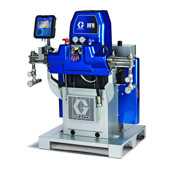
HFR
Foam - Cart
Hydraulic, Plural-Component, Fixed-Ratio Proportioner.
For dispensing NVH foam.
For professional use only. Not approved for use in explosive atmospheres or hazardous
locations.
Important Safety Instructions
Read all warnings and instructions in this
manual. Save these instructions.
See page 4 for model information and maximum
working pressure.
Patents Pending
for NVH
ti19507a
3A2797ZAA
EN
Advertisement
Table of Contents

Related Manuals for Graco HFR


Summary of Contents for Graco HFR
- Page 1 Setup - Operation ™ for NVH Foam - Cart 3A2797ZAA Hydraulic, Plural-Component, Fixed-Ratio Proportioner. For dispensing NVH foam. For professional use only. Not approved for use in explosive atmospheres or hazardous locations. Important Safety Instructions Read all warnings and instructions in this manual.
-
Page 2: Table Of Contents
HFR Hydraulic Power Pack ....17 Graco Information ......120 Motor Control Module (MCM) . -
Page 3: Related Manuals
HFRL and HFRS Setup and opera- tions Manual. 313998 HFR Repair-Parts 3A1704 Communications Gateway mod- Power Distribution Box Manual ule Installation Kit - for HFR or NVH systems 3A0239 Power Distribution Boxes Instruc- tions-Parts 312864 Communications Gateway Mod- ule, Instructions and Parts... -
Page 4: Models
Models Models Primary Primary Max Flow Approximate Maximum Full Load Heater Heater Rate◆ Output per Hydraulic Fluid Working Peak Amps Voltage Watts Watts lb/min Cycle (A+B) Pressure Pressure ‡ System Per Phase* (phase) A (Red) B (Blue) (kg/min) gal. (liter) Ratio psi (MPa, bar) 24N569... - Page 5 If 2000 psi hoses were purchased and installed by Graco, the working pressure for the machine is already setup for the lower 2000 psi (13.8 MPa, 138 bar) working pressure by Graco. If the machine was pur- chased without hoses and aftermarket hoses rated at or above 3000 psi are to be installed, see instruction man- ual 313998 for the procedure to setup the machine for higher rated hoses.
-
Page 6: Accessories
Accessories Accessories Applicator B (Blue) and A (Red) Feed Tanks Part Description Part Description 24J187 GX-16, 24:1, Straight, Machine Mount 24N594 20 gal. (75 l) Stainless Steel Tank, No Agitation, Insulation, 3 Level Sensors, A-Side 24K233 GX-16, 24:1, Left, Machine Mount 24N595 20 gal. -
Page 7: Additional Accessories
24K348 Pneumatic Agitator for 20 gal. (75 l) Stainless Steel Tank, 19C802 Token Assembly, HFR map with Data Exchange No Heat 19C885 Flash Drive, HFR Sample Program, Support Files, Sam- 24K346 Pneumatic Agitator for 20 gal. (75 l) Stainless Steel Tank, ple PLC Program... -
Page 8: Warnings
Warnings Warnings The following warnings are for the setup, use, grounding, maintenance, and repair of this equipment. The exclama- tion point symbol alerts you to a general warning and the hazard symbol refers to procedure-specific risk. Refer back to these warnings. Additional, product-specific warnings may be found throughout the body of this manual where applicable. - Page 9 Warnings WARNING FIRE AND EXPLOSION HAZARD Flammable fumes, such as solvent and paint fumes, in work area can ignite or explode. To help pre- vent fire and explosion: • Use equipment only in well ventilated area. • Eliminate all ignition sources; such as pilot lights, cigarettes, portable electric lamps, and plastic drop cloths (potential static arc).
- Page 10 Warnings WARNING EQUIPMENT MISUSE HAZARD Misuse can cause death or serious injury. • Do not operate the unit when fatigued or under the influence of drugs or alcohol. • Do not exceed the maximum working pressure or temperature rating of the lowest rated system component.
-
Page 11: Important Two-Component Material Information
Important Two-Component Material Information Important Two-Component Material Information Isocyanate Conditions Moisture Sensitivity of Isocyanates Isocyanates (ISO) are catalysts used in two component foam and polyurea coatings. ISO will react with mois- Spraying or dispensing materials containing isocya- ture (such as humidity) to form small, hard, abrasive nates creates potentially harmful mists, vapors, and crystals, which become suspended in the fluid. -
Page 12: Changing Materials
A (Red) and B (Blue) Components Changing Materials • When changing materials, flush the equipment mul- tiple times to ensure it is thoroughly clean. • Always clean the fluid inlet strainers after flushing. • Check with your material manufacturer for chemical compatibility. -
Page 13: Typical Installation
Wrap with tape during opera- . 1: Typical Installation Key: Tank Stand - A (Red) Tank Stand - B (Blue) AC Power Pack HFR Power Pack Dispense Gun Fluid Temperature Sensor (FTS) Manifold Main Hose Bundle Whip Hose Bundle 3A2797ZAA... -
Page 14: Component Identification
PHA Primary Heater - A Side FB Component B (Blue) Fluid Manifold Inlet Primary Heater Fluid Inlet FM HFR Fluid Manifold PO Primary Heater Fluid Outlet FP Feed Inlet Pressure Gauge PR Primary Heater RTD FT Feed Inlet Temperature Gauge... - Page 15 Component Identification Fluid Manifold (FM) Detail Rear View ti9880a1 ti19510a Primary Heater (PHB) Primary Heater (PHA) Detail, B (Blue) side shown Detail, A (Red) side shown (In Enclosure) ti19511a ti19509a . 3: Component Identification, Continued 3A2797ZAA...
- Page 16 Component Identification Main Power Switch Circuit Breakers Located on top of the power distribution box, see page . The main power switch turns power and OFF . The main power switch Most circuit breakers are located inside the power dis- does not turn pumps or heat zones on.
-
Page 17: Hfr Hydraulic Power Pack
Component Identification HFR Hydraulic Power Pack ti19514a . 4: HFR Hydraulic Power Pack Key: DA 9 Gallon Hydraulic Oil Reservoir (see Technical Data on DG Fan page 117 for specifications) DH Oil Filter DB Electric Motor DJ Shroud (not shown, removed for clarity) -
Page 18: Motor Control Module (Mcm)
(A) faces up. Motor Control Module or damage may occur. See HFR Repair manual for details, see Related Manu- The Motor Control Module uses an 8-position selector als on page 3. - Page 19 Component Identification Description Access Cover LEDs Warning Label 1A, 1B CAN Connections Three-way Splitter to: Oil Low Level Sensor, Dispense Valve Solenoid, and Footswitch Oil Temperature Sensor Electric Motor Temperature Sensor LVDT (Position Sensor) Three-way Splitter to: Hydraulic Directional Valve, Oil Overtemperature Switch Pressure Transducer B (Blue) side Pressure Transducer A (Red) side...
-
Page 20: Advanced Display Module (Adm)
Component Identification Advanced Display Module (ADM) User Interface TI12362a1 . 6: ADM Component Identification - Front Buttons Ref. Button Function Ref. Button Function Soft Defined by application using ADM. System Enables/disables system. When sys- Keys enable/ tem is disabled, temperature control disable and dispense operation are disabled. - Page 21 Component Identification r_24E451_3B9900_1a . 7: ADM Component Identification - Rear Key: CJ Flat Panel Mount CN Module Status LEDs CK Model Number CP Accessory Cable Connections CL USB Module Interface CR Token Access Cover CM CAN Cable Connections CS Battery Access Cover ADM Module Status LEDs (CN) Conditions Module Status LED Signal Description...
- Page 22 Component Identification Main Display Components The following figure calls out the navigational, status, and general informational components of each screen. For details regarding the user interface display see Shutdown, page 43. Current date and time Current chapter Next chapter Previous chapter (Right Arrow) (Left Arrow) Mode...
-
Page 23: Fluid Control Module (Fcm)
Component Identification Fluid Control Module (FCM) ti12337a1 ti12336a1 . 9: Fluid Control Module (FCM) Key: Fluid Control Module Access Cover Base Module Status LEDs Module Connection Screws CAN Connectors Diagnostic Information Module Status LED (Ref E) Signal Diagnosis Green on System is powered up Yellow Internal communication in progress... -
Page 24: Temperature Control Module
Component Identification Temperature Control Module Signals ti12352a1 ti12353a1 . 10: High Power Temperature Control Module Sensor Connections Key: Overtemperature Switch Connection (primary heaters DC Output Connection only) Input Power Connection RTD Temperature Sensor Connection CAN Connections Output Power Connection Rotary Selector Switch, Token Access Signals ti12356a1 ti12357a1... - Page 25 Component Identification Temperature Control Module Diagnostic Heat Control Zone Selection Information The HFR unit supports four independent temperature control zones and two independent temperature moni- Module Status LEDs toring zones. The high power temperature control mod- ules are located inside the frame below the hydraulic...
- Page 26 Component Identification Adjust Rotary Switch High Power Module Rotary Switch Settings Setting Zone The rotary switch setting indicates which zone the tem- perature control module will control in the system. The Not Used high power module uses an 8-position rotary switch. B (Blue) Primary Heat The low power module uses a 16-position rotary B (Blue) Hose Heat...
-
Page 27: Setup
Setup Setup Perform this setup procedure to secure all necessary Ground system machine connections for machine operation. Locate system. This equipment must be grounded. a. Locate system on a level surface. See Dimen- sions on page 119 for space requirements. b. - Page 28 Setup NOTE: Power cord is not supplied. See the following The MAX-HOLD feature on a multimeter can be used to table. determine peak DC voltage on the line. DC is the proper setting, as opposed to AC, because peak voltage is the critical parameter that affects the DC voltage level Table 2: Power Cord Requirements stored on the capacitive bus in power conversion...
- Page 29 Setup Connect HFR Proximity Cables to the GX-16. Connect Hydraulic Lines to the system. NOTE: Refer to the HFR and GX-16 manuals for more NOTICE details for the following procedures. Damage can occur to the directional valve if the NOTE: The cable is indicated by a green stripe.
- Page 30 Install JIC #6 fitting assembly into the B Return port. d. Install JIC #8 fitting assembly into both A Sup- Install PrePoly Refresh Kit (Optional). ply and A Return ports. Refer to HFR for NVH Prepoly Refresh Kit, Instruc- tions-Parts for installation and setup instructions. 3A2797ZAA...
- Page 31 Setup 3A2797ZAA...
- Page 32 Setup Step 10d Step 7a, Step 7b, Step 7c, Step 7d Step 10f ti19507a . 15: Material Hose Connections 3A2797ZAA...
- Page 33 Ensure A (Red) and B (Blue) inlet valves on the and whip hose. Connect the main hose bundle to the whip hose bundle. HFR and the material supply ball valves on the tanks are closed. NOTE: The ball valve kit is designed to fit in one orien- tation only.
- Page 34 Setup h. Connect cables (Y). Be sure cables have slack Connect GX-16 Hydraulic Lines when hose bends. Wrap cable and electrical connections with electrical tape. See Heated Hose manual for heated hose connection details and illustrations for the various types of heated hoses.
- Page 35 . 19. ti14496a . 20: Hydraulic Connections k. Attach trigger switch cable (if applicable) to gun and HFR. . 19 Circulate oil for 3 minutes to purge air from hydraulic hoses. NOTE: Pressure should not increase while air is purged from hoses.
- Page 36 57 for more detail. ization is complete. c. Calibrate HFR, page 37. See Calibration Screen, Main, page 58 for more detail. d. Define pump information. See System Screen 1, page 59 for more detail.
- Page 37 This equipment is used with heated fluid, which can The HFR calibration procedure is a two step process. cause equipment surfaces to become very hot. To The first step, Learn Mode, must be performed when-...
- Page 38 Setup a. Navigate to System Screen 3. Flush the System b. Press to enter the screen. c. Navigate to the pressure imbalance field. NOTE: System components will contain testing oil from the factory. Perform the following procedure when the d. Type the desired pressure imbalance setting machine is initially installed.
- Page 39 Connect the applicator return hose to the fluid inlet fitting on the system. ti10006a1 g. Turn HFR main power ON h. Navigate to the System Setup Screen. Set the low pressure dispense to 25%. NOTE: The following steps are referring to the B side (Blue) components of the system.
- Page 40 Setup Install GX-16 Orifices Pressure check hose See hose manual. Pressure check for leaks. If no leaks, wrap hose and electrical connections to protect from damage. a. Close both A side (Red) and B side (Blue) feed Check hydraulic fluid level inlet valves on the system.
- Page 41 Setup 20. I 21. I nstall High Volume Fill Kit (Optional). nstall Low Volume Fill Kit (Optional). r_24m418_3a1961_1a r_24m419_3a1961_1a . 24: High Volume Refill Kit . 25: Low Volume Refill Kit a. Perform Pressure Relief Procedure, page 43. a. Perform Pressure Relief Procedure, page 43. b.
-
Page 42: Startup
Startup Startup To reduce the risk of personal injury, do not operate HFR without all covers and shrouds in place. 1. Check that all machine connections are setup. See 6. Navigate to Home Standby screen and press Setup procedure, page 27. -
Page 43: Shutdown
Shutdown Shutdown Pressure Relief Procedure 1. Park pumps. a. From the Home screen, press and select 1. Press to disable the ADM. Standby mode. 2. Shut off feed pumps and agitator, if used. 3. Turn PRESSURE RELIEF/DISPENSE valves (SA, b. Press . -
Page 44: Flushing
Flushing Flushing • To maintain grounding continuity when flushing or relieving pressure, hold a metal part of dispense gun firmly to the side of a grounded metal pail, then trigger gun. Flush equipment only in a well-ventilated area. Do not dispense flammable fluids. -
Page 45: Maintenance
Icons on page 52. If fluid is dark in color, change fluid and filter. Verify vent holes on bottom of Weekly electrical cabinet are clear and unobstructed Inspect HFR Powerpack air filter Weekly (part 24H018), clean or replace as necessary, Use compressed air to remove Monthly... -
Page 46: Install Upgrade Tokens
- Discrete Gateway Module page 68 in Appendix B - ADM Setup Screens Over- - Communication Gateway Module view for a list of the HFR module software components. 16G407 Ratio Monitoring (Flow Meters): - Fluid Control Module On system software version 1.12.014 and later (Octo-... - Page 47 Maintenance 1. Enter the system into Disable mode by pressing the 5. Navigate to the Advanced 8 screen, shown below. The system version of the software currently on the machine is provided (“1.12.013” in the screen mode selection key ( ) from the main home run below).
- Page 48 100% completion and the token will now contain the selected file on the USB stick. 12. To program the HFR with the token software, press key. If the token will be used for another system, remove the token and exit the screen(s) by pressing the Cancel key.
-
Page 49: Troubleshooting
Troubleshooting Troubleshooting Light Tower (Optional) Signal Description Green on only System is powered up and there are Before performing any troubleshooting procedure: no error conditions present Yellow on An advisory exists 1. Perform Pressure Relief Procedure on page 43. Red flashing A deviation exists 2. - Page 50 Troubleshooting PROBLEM CAUSE SOLUTION Material does not maintain Ambient temperature is too cold Increase A (Red) and B (Blue) setpoints to increase temperature while spraying fluid temperature and keep it steady Flow too high Use smaller mix chamber. Decrease pressure. Material temperature Faulty RTD connections Verify that all FTS connections are snug and that pins...
-
Page 51: Appendix A - Adm Icons Overview
Appendix A - ADM Icons Overview Appendix A - ADM Icons Overview Setup Screen Icons Icon Description Icon Description Erase All Counters on Page Enter Screen Access Flowmeter Calibration Exit Screen On Learn Mode Calibration screen: Valve Details Move pump Selects all shots to be changed to the All other screens: same user specific value... -
Page 52: Run Screen Icons
Appendix A - ADM Icons Overview Run Screen Icons Icon Description Icon Description Sets machine to low pressure Select mode. Set system in park (icon will be Sets machine to high pressure selected when system is parked) Current and setpoint temperature for Open, Close Valve primary heater. -
Page 53: Appendix B - Adm Setup Screens Overview
Appendix B - ADM Setup Screens Overview Appendix B - ADM Setup Screens Overview The ADM will start in the Run screens at the “Home” From the Setup screens, press to access the Run screen. From the Run screens, press to access screens. - Page 54 Appendix B - ADM Setup Screens Overview Shots Screen Due to variation in material properties, the ∆ column gives the ability to adjust the shot time/volume/weight This screen allows the user to edit shot definitions. The for each defined shot. contents of this screen change based on the flow units selection.
- Page 55 Appendix B - ADM Setup Screens Overview 4. Use the following formula to calculate the ∆ column Volume/Weight Based Example: value. A 75 cc/s shot is defined to dispense for 75 cc. ((Flow Rate x Time) - Average Volume) Flow Rate Example 1: ((75cc/sec x 2sec) - 146cc) = 0.053 sec...
- Page 56 Appendix B - ADM Setup Screens Overview 5. Enter the calculated value in the ∆ column. 3. Press to activate the option. Example 3: To edit a shot definition: 1. Navigate to Shots Screen. Shot Calibration Table This screen allows the user to set the offset, ∆(g), for a 2.
- Page 57 Blank positions (containing a 0) in sequence will be skipped by the HFR sequence logic. 5. Calculate the offset of each shot size and record For example, sequence “Y” in the screen shown below the data.
- Page 58 Calibration Screen, Main This screen shows calibration information for the sys- tem and provides access to other calibration screens. See Calibrate HFR on page 37 for how to use the cali- Previously saved left Previously saved right bration screens to calibrate the machine.
- Page 59 P2/Fusion Dispense Valves. This feature can not be active if the Pre Dispense Delay feature is active. Pre Dispense Delay is a feature where the HFR can delay the start of a dispense until the user has pressed and held the foot switch for the duration entered.
- Page 60 Appendix B - ADM Setup Screens Overview Mix Head Operating Details Screen System Screen 3 This screen allows the user to define the mix head This screen allows the user to edit the labels for the A operating parameters. (Red) and B (Blue) sides of the machine. The labels set for the A (Red) and B (Blue) sides of the machine are •...
- Page 61 Appendix B - ADM Setup Screens Overview Keyboard Screen Maintenance Screen This screen is used to edit the A (Red) and B (Blue) This screen shows shot number, sequence position, labels on the ADM. Use arrow keys to select the desired dispense valve, and accumulator charge cycle count- letter and press to accept the letter.
- Page 62 • A button is provided to the user on the run • If active (checked ) the HFR (or NVH) will report screens to initiate a manual refill operation at a full tank high level condition (top sensor any time detects material) as a 7, rather than 3 (bit 2 set •...
- Page 63 Appendix B - ADM Setup Screens Overview If a refill setting other than Disabled is selected, the user Conditioning Screen 1 must set at least two level sensor locations as installed This screen allows the user to select which temperature by checking the check box on the screen.
- Page 64 Appendix B - ADM Setup Screens Overview Conditioning Screen 3 This screen allows the user to configure Night Mode operation. In Night Mode, the system will cycle on and off periodically or turn on at a preset time. Press and select periodic or time schemes. When the system is in Night Mode and in an “On”...
- Page 65 Appendix B - ADM Setup Screens Overview To set the on/off machine times: 6. To erase times, repeat steps 1 thru 3 and press once the desired time duration has been 1. Press to enter the screen. selected. 2. Press left or right arrow keys to highlight the day NOTE: If times are entered in the weekly schedule, indi- selection column.
- Page 66 OFF (not recommended for production use). If a cavitation error is generated, it informs the user that one of the HFR pumps may not have properly filled, and the ratio of the two materi- als may not be correct. When the state of this control is changed, an ECC1 event (“Cavitation...
- Page 67 3 cycles/minute. information about USB operation, see Appendix F - USB Operation on page 91. For more information NOTE: If the HFR is in pressure mode, the selection about the optional screens, see Diagnostic screen is not relevant.
- Page 68 (default is NOT checked), will command the (not greyed out) if the corresponding tank system is HFR to interpret a footswitch tap as a go to high pres- online. If the function is enabled (checked) the tank sure recirculation mode, but will NOT dispense material...
- Page 69 • Light Tower Options - If using the light tower option for the HFR, the user must select the correct light tower option used with their system. The Stan- dard 3 Light and Custom Clear Lens options are currently available using the drop-down selection.
-
Page 70: Appendix C - Adm Run Screens Overview
Appendix C - ADM Run Screens Overview Appendix C - ADM Run Screens Overview Run screens are divided into five major sections: status, errors, events, and maintenance. The following diagram demonstrates the flow of the Run screens beginning with the Home screen. Home Status Errors #1... - Page 71 Appendix C - ADM Run Screens Overview Home Screen, Standby Mode Home Screen, Shot Mode In Standby Mode, the user can enable heating, park the This mode allows the user to select one of 100 pre- pumps, refill the tanks, circulate materials. defined shot numbers.
- Page 72 Appendix C - ADM Run Screens Overview Home Screen, Sequence Mode 7. Press to abort the sequence. This mode allows the user to select one of five sequences (A-E). The progress bar on the bottom of the 8. See Home Screen, Shot Mode on page 71 for screen shows the progress of a shot dispensing from other button functions.
- Page 73 Appendix C - ADM Run Screens Overview Home Screen, Night Mode Status Screen, Conditioning Control This screen allows users to turn on and off heat zones In Night Mode, the system will cycle on and off individually or all at once. When a zone is on it is periodically or turn on at a preset time.
- Page 74 Appendix C - ADM Run Screens Overview Errors Screens Maintenance Screen This screen shows users a list of errors that have This screen displays historical information for each occurred in the system. Each error entry includes a pump in the system. The Batch counters are resettable description and error code along with a date and time and count both material usage and pump cycles.
- Page 75 Appendix C - ADM Run Screens Overview Optional Screens The optional Diagnostic screen can be enabled in the Advanced Screen 4 screen, see page 67. Diagnostic The Diagnostic screen shows status information for various components in the Motor Control Module. 3A2797ZAA...
-
Page 76: Appendix D - Adm Error Codes
Appendix D - ADM Error Codes Appendix D - ADM Error Codes Error Error Code Error Name Error Description Type Cause Solution Red Hose A4A2 Overcurrent Red Inline A4A3 Bad heaters Measure resistance of heater Overcurrent Red Blanket A4A6 Overcurrent Red Chiller Measure voltage across the disconnect switch. - Page 77 Check for MCM software update, load latest MCM A9C1 commanding too much Current Module code software, if problem persists contact Graco current On the ADM go into the Setup screens to the System Pumps are defined with The requested dispense...
- Page 78 Voltex Mixer Module is Off line CAN cable to Voltex Reconnect, ensure cable. Verify proper LED Comm. Error CAD1 Alarm (HFR Only) FCM3 is disconnected. indications on Voltex FCM3. Mixer FCM3 failure. PLC is not maintaining Ensure PLC is triggering the heartbeat...
- Page 79 Appendix D - ADM Error Codes Error Error Code Error Name Error Description Type Cause Solution System underwent a change that caused a Erase learned System Data, found in the setup Setpoint large drop in restriction screens under calibration D3A1 The set point was exceeded Deviation (such as new orifices)
- Page 80 Appendix D - ADM Error Codes Error Error Code Error Name Error Description Type Cause Solution Failure of the dispense Ensure the valve has a proper air supply and seals When the pump tried to stall to valve properly. If not, service the valve as necessary. pressure the pump traveled Pump Failed Visually inspect the machine and hoses for sign of...
- Page 81 Appendix D - ADM Error Codes Error Error Code Error Name Error Description Type Cause Solution Visually check to ensure the pump is moving, if not Motor failure ensure the motor is wired properly If motor is moving but pump is not and pressure is Hydraulic power pack not building they hydraulic power pack may need failure...
- Page 82 Appendix D - ADM Error Codes Error Error Code Error Name Error Description Type Cause Solution High Alarm Accumulator Directional Check control line to Directional Valve. Replace AC Power Pack pressure too P4H3 Accumulator Valve stuck in charge Directional Valve. high Pressure position.
- Page 83 Appendix D - ADM Error Codes Error Error Code Error Name Error Description Type Cause Solution Red Hose T2AA Low Fluid Temp. Red Tank T2AE Low Fluid Temp. Temperature is out of Check temperature alarm limits Red Chiller alarm limits T2AF Low Fluid Fluid temperature for a...
- Page 84 Appendix D - ADM Error Codes Error Error Code Error Name Error Description Type Cause Solution Red Hose T4A2 High Fluid Temp. Red Inline T4A3 High Fluid Temp. Red Tank T4A6 High Fluid Temp. Defective Temperature Replace Power Temperature Control Module Control Module Red Chiller T4A7...
- Page 85 Appendix D - ADM Error Codes Error Error Code Error Name Error Description Type Cause Solution Red Hose T6A2 FTS Fault Red Inline T6A3 RTD Fault Red Tank T6A6 RTD Fault Red Chiller T6A7 Loose or bad connection Check RTD wiring RTD Fault RTD 1 is giving no or invalid data...
- Page 86 Voltex mixer failed to spin, Mixer clogging, or mixed Verify mixer reaching requested RPM using the Mixer WBD1 Deviation Fault operate (HFR Only) material hardening Run screen. Clean or replace mixer if necessary. Motor An error has been detected on WBH1...
- Page 87 Appendix D - ADM Error Codes Error Error Code Error Name Error Description Type Cause Solution Deviation Material Rod stuck Take a long shot to determine if it corrects the Material rod in dispense valve closed. Shot duration problem. M1 Material too short.
- Page 88 Appendix D - ADM Error Codes Error Error Code Error Name Error Description Type Cause Solution Blue Inline WMC1 Con. Fault Red Hose WMC2 Con. Fault Red Inline WMC3 Con. Fault Blue Hose WMC4 Con. Fault Blue Tank WMC5 Con. Fault Red Tank If temperature is being affected by a zone that has WMC6...
-
Page 89: Appendix E - System Events
The custom language file was suc- using the ADM module or Field Bus Downloaded cessfully transferred from the ADM to interface. If turned OFF, and an HFR a USB drive. pump does not completely fill, the error will NOT be generated and the... - Page 90 Appendix E - System Events Event Code and String Triggers ERB3-R: Blue Cycle The resettable cycle counter for the Count Reset Blue pump was reset to zero. EWA0-R: Prepoly While in night mode, the prepoly Refresh Canceled refresh was canceled REQU-R: Settings The system settings file was success- Uploaded...
-
Page 91: Appendix F - Usb Operation
Appendix F - USB Operation Appendix F - USB Operation Overview The third option is a checkbox that enables or disables the ability to record errors associated with the USB logs. There are 3 main uses for the USB on a GMS system: •... -
Page 92: Log Files, Folder Structure
Appendix F - USB Operation Log Files, Folder Structure . 29: DOWNLOAD, DATAxxxx Folders Each time a stick-drive is inserted into the ADM USB port, a new folder named DATAxxxx is created. The number at the end of the folder name is incremented each time a stick-drive is inserted and data is downloaded or uploaded. In each DATAxxxx folder there are three log files. - Page 93 Appendix F - USB Operation Example 2-JOB File The 2-JOB file is the Shot Data Log file. Example 3-SYSTEM File The 3-SYSTEM file is the Software Version log file. 3A2797ZAA...
-
Page 94: Transfer System Settings
The user should never attempt to modify the SET- remove the SETTINGS.TXT file from the UPLOAD folder TINGS.TXT file in any way. Graco is not responsible to prevent accidental loss of data the next time the USB for damages caused by an improperly modified stick-drive is inserted into the ADM USB port. -
Page 95: Update Custom Language
Appendix F - USB Operation Update Custom Language 8. When the software is done updating, remove the NOTICE USB stick-drive from the ADM USB port and install Low-quality USB stick drives may lead to burning in a computer. out the USB port on the ADM. Use only high-qual- 9. - Page 96 Appendix F - USB Operation Example SETTINGS.TXT File NOTICE The user should never attempt to modify the SET- TINGS.TXT file in any way. Graco is not responsible for damages caused by an improperly modified setup file. Example DISPTEXT.TXT File 3A2797ZAA...
-
Page 97: Appendix G - Communications Gateway Module
PLC. See Available Internal Data, page 101 for a list of internal data from and to the HFR/ NVH system that can be viewed or modified by the PLC/ Robot fieldbus master. The data in that section is intended to be an... -
Page 98: Setup - Gateway Screens
Appendix G - Communications Gateway Module Installation Kit 6. If Used, connect the Ethernet, DeviceNet, or Profibus cable to the CGM as applicable. Connect the other end of the cable to the FIeldBus device. See F . 34 #10-32 UNF (M5 x 0.8) 2.75 in. - Page 99 Appendix G - Communications Gateway Module Installation Kit Screen 1 This screen enables the user to set the device address, and baud rate, and to view the hardware revision, This screen enables the user to set the IP address, system serial number, and data map identification DHCP settings, subnet mask, gateway, and DNS information.
- Page 100 Appendix G - Communications Gateway Module Installation Kit Screen 2 Screen 2 This screen displays the hardware revision, system This screen enables the user to set the station name serial number, and data map identification information. install date location tag, function tag, and description. See F .
-
Page 101: Available Internal Data
Values are subject to the same maximum and Recirculation Valve I170 minimum restrictions of the ADM Opened (HFR Only) System Startup I171 Input data (Signals from HFR/NVH to PLC/ Command Active Controlling Logic) I172 Pumps are Parked Instance Byte(s) Input Description... - Page 102 HFR or NVH system. Request (ADM, PLC & Footswitch). @ Dispense Request to the HFR is similar to a dispense request using a foot switch (Operator Mode – Press TBD Bit Command1 and hold (= 1) entire shot duration, Shot & Sequence...
-
Page 103: Run Screens Available Data
The second run screen, the Fieldbus commands screen provides graphical representations for the control data requested from the PLC or robot to the HFR/ NVH logic. The commands screen provides a green graphic when a bit request is on (high), and a grey graphic when the bit command is off or low. -
Page 104: I/O Signal Descriptions
The rate is determined if the machine is in constant flow or constant pressure modes. The This bit must be set (high) before the HFR or NVH will amount is determined if in volumetric, weight, or a time honor any output request from the PLC, robot or based amount mode. -
Page 105: Data Exchange Interface
System is “Ready” for Dispense Request. This is bi-directional interface which provides both (I175): transmit and reception of data between the HFR/ NVH system, and the controlling logic (PLC, robot or This informs the controlling logic it is OK to request a equivalent). - Page 106 21, O160 – O175) a value corresponding to the data the PLC wants to transmit to the HFR. 3. The HFR will echo back to the PLC the data pointer and the data element after the HFR system processes the data transmit request to input locations 26 –...
-
Page 107: Data Exchange Interface Pointer Designation Table
Appendix G - Communications Gateway Module Installation Kit Data Exchange Interface Pointer Designation Table Data Exchange Read/ Pointer Description Comments, Data Element Descriptions Write Designation Interface Not Active ----- Red Material Tank Write Heat, Set point Set or Get Set Point temperature, in 0.1 C units. - Page 108 In 0.001:1 units of measure. So for instance, a value of 23721 = 23.721:1. Ratio may be inverted based on the setting of the Ratio, Actual “Ratio:” control selection on the System #3 setup screen. This Read data is only valid if HFR or NVH has a Ratio Monitoring option installed. 3A2797ZAA...
- Page 109 See error number table in next section. Writing to this register Write with the error number read, will clear the Error code pop-up win- Error number dow from the HFR screen. If the condition is still present after requiring acknowledgment, the same error number acknowledged will be Acknowledgement Read provided in the next read instruction below.
- Page 110 Sum of Blue and Red material dispensed from HFR or NVH (In 1 Write Counter CC or 1 Gram units) Blue Material Total Sum of Blue material dispensed from HFR or NVH (In 1 CC or 1 Read Counter Gram units) Red Material Total...
- Page 111 Read State/ Request Set (Write) or get (read) the recirculation flow rate set point in in Write Recirculation Flow 0.01 cc/sec, 0.01 g/sec units (HFR Systems with Circulation Rate Set Point Read Valves Installed). Low pressure Set (Write) or get (read) the Low pressure Circulation flow rate...
-
Page 112: Error Number Tables
Number The following table documents all the possible error Blue Motor Controller WMH1 numbers and codes generated by a HFR or NVH sys- Fault tem. If no error is present, a 0 will be provided in the Blue Motor Low corresponding register (No Active Errors). - Page 113 Appendix G - Communications Gateway Module Installation Kit Error Error Item # Code Level Description Item # Code Level Description Number Number B9C1 Small Shot Request Red Inline Control A7A3 Fault Red Pressure P4A1 Shutdown Blue Inline Control A7B1 Fault DDA1 Red Pump Cavitation Red Hose Control...
- Page 114 Appendix G - Communications Gateway Module Installation Kit Error Error Item # Code Level Description Item # Code Level Description Number Number Red Tank Con. Red Hose Low Fluid WMC6 T1A2 Cutback Temp. Blue Tank Con. Blue Hose Low Fluid WMC5 T1B4 Cutback...
- Page 115 Appendix G - Communications Gateway Module Installation Kit Error Error Item # Code Level Description Item # Code Level Description Number Number No Cooling Blue Red Hose Con. Fault T8B8 WMC2 Chiller (Unexpected Relay I) T6A6 Red Tank RTD Fault Blue Hose Con.
- Page 116 Appendix G - Communications Gateway Module Installation Kit Error Error Item # Code Level Description Item # Code Level Description Number Number F3A0 High Flow Red Field Bus Heartbeat CUCN Failure F4B0 High Flow Blue Comm. Error Discrete F3B0 High Flow Blue CACP F1A0 Low Flow Red...
-
Page 117: Technical Data
Technical Data Technical Data HFR for NVH Foam Metric Maximum fluid working pressure 2000 psi 14 MPa, 138 bar Maximum Fluid Temperature 180°F 82°C Fluid Inlet Feed Pressure Range 50 psi to 100 psi 345 kPa, 3.4 bar to 0.7 MPa, 7 bar... -
Page 118: Motor Control Module Technical Data
Three Phase Output Current 0-30A Output Overload 200% for 0.2 seconds DC Power Supply 24 Vdc, Class 2, Graco-provided power supply Enclosure Type 1 Max Ambient Temperature 50°C (122°F) Overtemperature protection is provided to protect from motor overload. Current limit, set via the software, is provided as a secondary protection from motor overload. -
Page 119: Dimensions
California Proposition 65 Dimensions ti19519a Dimensions A (Height) 76 in. (193 cm) B (Width) 72 in. (183 cm) C (Length) 58 in. (147 cm) California Proposition 65 CALIFORNIA RESIDENTS WARNING: Cancer and reproductive harm – www.P65warnings.ca.gov. 3A2797ZAA... -
Page 120: Graco Standard Warranty
With the exception of any special, extended, or limited warranty published by Graco, Graco will, for a period of twelve months from the date of sale, repair or replace any part of the equipment determined by Graco to be defective.
Need help?
Do you have a question about the HFR and is the answer not in the manual?
Questions and answers